Language selection

Search

Patent 2221613 Summary

Third-party information liability

Some of the information on this Web page has been provided by external sources. The Government of Canada is not responsible for the accuracy, reliability or currency of the information supplied by external sources. Users wishing to rely upon this information should consult directly with the source of the information. Content provided by external sources is not subject to official languages, privacy and accessibility requirements.

Claims and Abstract availability

Any discrepancies in the text and image of the Claims and Abstract are due to differing posting times. Text of the Claims and Abstract are posted:

  • At the time the application is open to public inspection;
  • At the time of issue of the patent (grant).
(12) Patent: (11) CA 2221613
(54) English Title: CYCLONE
(54) French Title: CYCLONE
Status: Expired and beyond the Period of Reversal
Bibliographic Data
(51) International Patent Classification (IPC):
  • B04C 5/13 (2006.01)
  • B01D 45/12 (2006.01)
(72) Inventors :
  • HALLDIN, CLAES (Sweden)
  • JOHANSSON, LARS-ERIK (Sweden)
  • SALO, HEIKKI (Sweden)
(73) Owners :
  • ANDRITZ TECHNOLOGY AND ASSET MANAGEMENT GMBH
(71) Applicants :
  • ANDRITZ TECHNOLOGY AND ASSET MANAGEMENT GMBH (Austria)
(74) Agent: GOWLING WLG (CANADA) LLPGOWLING WLG (CANADA) LLP
(74) Associate agent:
(45) Issued: 2006-05-16
(86) PCT Filing Date: 1995-05-30
(87) Open to Public Inspection: 1996-12-05
Examination requested: 2002-03-19
Availability of licence: N/A
Dedicated to the Public: N/A
(25) Language of filing: English

Patent Cooperation Treaty (PCT): Yes
(86) PCT Filing Number: PCT/SE1995/000607
(87) International Publication Number: WO 1996038231
(85) National Entry: 1997-11-19

(30) Application Priority Data: None

Abstracts

English Abstract


A cyclone for treating a gas flow (F) containing dust comprises a cyclone
chamber (1) of circular cross section and having a vertical axis, and a
central tube
(7) of circular cross section, which is coaxially arranged in the upper
portion of the
cyclone chamber (1). An elongate insert element (10), which is vertically
inserted
in the central tube (7), is so designed and extends in such a manner downwards
in the central tube (7) from the upper end thereof that a circumferential gap
(17)
exists between the insert element (10) and the central tube (7). This gap (17)
has
a preferably constant cross-sectional area which does not increase in the
direction
of the gas flow.


French Abstract

Cyclone destiné au traitement d'un courant gazeux (F) contenant des poussières, comportant une chambre (1) de cyclone de section circulaire et pourvue d'un axe vertical, et un tube central (7) de section circulaire, disposé coaxialement dans la partie supérieure de la chambre (1) de cyclone. Un élément d'insertion (10) allongé, inséré verticalement dans le tube central (7), est conçu et s'étend de telle façon vers le bas dans ledit tube (7), à partir de l'extrémité supérieure de ce dernier, qu'il existe un espace circonférentiel (17) entre l'élément d'insertion (10) et le tube central (7). Cet espace (17) a une superficie de section de préférence constante qui n'augmente pas dans la direction du courant gazeux.

Claims

Note: Claims are shown in the official language in which they were submitted.

-6-
We claim:
1. A cyclone for treating a gas flow containing dust, comprising:
a cyclone chamber of circular cross-section, the cyclone chamber having a
vertical
axis, said chamber having a gas flow inlet for injection of a gas flow into
the cyclone
chamber substantially horizontally relative to the vertical axis, and a lower
dust outlet
for removing dust separated from the gas flow in the cyclone chamber;
a central tube of circular cross-section, the central tube being coaxially
arranged in
an upper portion of said cyclone chamber, a lower end of the central tube
forming a
lower gas flow inlet and an upper end of the central tube forming an axially
arranged
upper gas flow outlet; and
an elongate insert element, the elongate insert element being vertically
inserted in
the central tube and extending downwardly in the central tube to define, with
the
central tube, a circumferential gap through which the gas flow flows to the
upper gas
flow outlet, said gap having a non-increasing cross-sectional area in a
direction of the
gas flow, and wherein a total length of the insert element is greater than
three times a
diameter of the central tube.
2. The cyclone as claimed in claim 1, wherein the gap has a substantially
constant cross-sectional area.
3. The cyclone as claimed in claim 1 or 2, wherein the insert element projects
above the central tube.
4. The cyclone as claimed in any one of claims 1 to 3, wherein the insert
element extends downwards to the lower end of the central tube.
5. The cyclone as claimed in any one of claims 1 to 4, wherein the insert
element is rotationally symmetrical.
6. The cyclone as claimed in any one of claims 1 to 5, wherein the insert
element and the central tube are coaxially arranged.

-7-
7. The cyclone as claimed in any one of claims 1 to 6, wherein the insert
element is hollow.
8. The cyclone as claimed in claim 7, wherein the insert element includes a
closure at an upper end thereof.
9. The cyclone as claimed in claim 7 or 8, wherein said insert element
includes a
conical closure at a lower end thereof.

Description

Note: Descriptions are shown in the official language in which they were submitted.


CA 02221613 1997-11-19
WO 96138231 PCTlSE95/00607
1
CYCLONE
The present invention relates to a cyclone for
treating a gas flow containing dust, said cyclone having
a cyclone chamber of circular cross-section and a verti-
cal axis, said chamber having a gas flow inlet for sub-
s stantially horizontal injection of the gas flow into the
cyclone chamber, and a lower dust outlet for removing
dust, which is separated from the gas flow in the cyclone
chamber, and a central tube of circular cross-section,
which is coaxially arranged in the upper portion of the
cyclone chamber and whose lower end foams a lower gas
flow inlet and whose upper end forms an upper gas flow
outlet.
A cyclone of this type is used as, for example, dust
separator in plants for drying paper pulp or some other
fibrous pulp, an air flow containing particles, such as
fibres, being passed through the cyclone so as to be
relieved of particles.
In operation, the cyclone is subjected to strong
vibrations, which, especially if the cyclone is large,
may cause its shaking to pieces. These vibrations are
probably caused by a flow phenomenon which is called PVC
(Precessing Vortex Core) and is described in more detail
by A K Gupta, D G Lilley and N Syred in "Swirl Flows",
pp 191-198, published in 1984 by ABACUS PRESS, Massachu-
setts, USA.
The object of the present invention is to provide a
cyclone, in which the PVC phenomenon and, thus, the prob-
lem of vibrations are eliminated or at least reduced to a
considerable extent.
According to the invention, this object is achieved
by a cyclone, which is of the type mentioned by way of
introduction and characterised in that an elongate insert
element, which is vertically inserted in the central
tube, is so designed and extends in such a manner down-

CA 02221613 1997-11-19
R'O 96/38231 PCTlSE95/00607
2
wards in the central tube from the upper end thereof that
a circumferential gap exists between the insert element
and the central tube, said gap having a preferably con-
stant cross-sectional area that does not increase in the
direction of the gas flow.
In a preferred embodiment, the insert element pro-
jects a distance above the central tube. '
Preferably, the insert element extends down to the
lower end of the central tube.
In a preferred embodiment, the insert element is
rotationally symmetrical and suitably coaxially inserted
in the central tube.
The insert element suitably is hollow. The hollow
insert element can have a closure at its upper and/or
lower end.
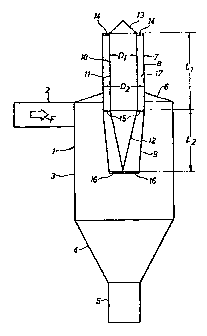
The invention will now be described in more detail
with reference to the accompanying drawing, which is a
schematic longitudinal section of a cyclone according to
the present invention in the axial direction.
The cyclone illustrated in the drawing comprises a
cyclone chamber 1 of circular cross-section and having a
vertical axis. A horizontal inlet pipe 2, which forms an
upper gas flow inlet, extends substantiallytangentially
into the cyclone chamber 1 in the upper portion thereof.
A fan (not shown) is arranged to inject, via the inlet
pipe 2, a dust-containing gas flow F, for example an air
flow containing fibres, into the cyclone chamber 1.
The cyclone chamber 1 comprises, in the shown embo-
diment, a circular-cylindrical portion 3, a truncated
conical portion 4, which is connected to the lower part
of the circular-cylindrical portion 3, a circular-cylind-
rical portion 5, which is connected to the lower part of
the truncated conical portion 4, and a truncated conical
portion 6, which is connected to the upper part of the
circular-cylindrical portion 3 and forms the top of the
cyclone chamber 1. The cyclone chamber portions 3, 4, 5
and 6 are coaxially arranged. The lower portion 5 forms a

CA 02221613 1997-11-19
wo 96138231 PCT/SE95/00607
3
lower dust outlet for removing dust or particles, e.g.
fibres, which are separated from the gas flow in the
cyclone chamber 1.
A central tube 7 of circular cross-section is
coaxially arranged in the circular-cylindrical portion
3
of the cyclone chamber 1 and extends, via the truncated
conical portion 6 thereof, out of the cyclone chamber 1.
The central tube 7 comprises a circular-cylindrical tubu-
lar portion 8 and, connected to the lower end thereof,
a
truncated conical tubular portion 9. The central tube 7
forms at its lower end a lower gas flow inlet and at its
upper end an upper gas flow outlet.
The cyclone as described so far is of the conven-
tional type. Its function thus is well-known to the
expert and will therefore not be described in more
detail.
An elongate insert element 10 of circular cross-sec-
tion is coaxially arranged in the central tube 7. The
insert element 10 comprises a circular-cylindrical tubu-
lar portion 11 and, connected to the lower end thereof,
a
. conical portion 12. The upper end of the tubular portion
11 and the lower end of the conical portion 12, i.e. the
tip of the cone, are positioned on the same level as the
upper and lower end, respectively, of the central tube
7.
The transition between the portions 8 and 9 of the cen-
tral tube 7 and the transition between the portions 11
and 12 of the insert element 10 are positioned on sub-
stantially the same level.
The insert element has at its upper end a conical
closure part 13, which projects above the upper end of
the central tube 7. The cone angle of the closure part
13 is about 90.
The insert element 10 is attached in the central
' tube 7 by means of three sets of intersecting radial arms
14, 15, 16, which are connected to the central tube 7,
' viz. a set of upper arms 14, which are connected to the
insert element 10 at the transition between the tubular

CA 02221613 1997-11-19
WO 96/38231 PCT/SE95/00607
4
portion 11 and the closure part 13 thereof, a set of
intermediate arms 15, which are connected to the insert
element 10 at the transition between the two portions 11
and 12 thereof, and a set of lower arms 16, which are
connected to the insert element 10 at the lower end '
thereof, i.e. at the tip of the cone.
The insert element 10 is so dimensioned and so '
arranged in the central tube 7 that a circumferential gap
17 exists between the insert element 10 and the central
tube 7. The dimensions of this gap 17 in the upper part
of the central tube 7, i.e. between the circular-cylind-
rical tubular portions 8 and 11 of the central tube 7 and
the insert element 10, are, in the embodiment illustrat-
ed, given by the ratio of the diameter D1 of the tubular
portion 11 to the diameter D2 of the tubular portion 8,
to which suitably applies that 0.3 < D1/D2 < 0.9, espe-
cially 0.63 < D1/D2 < 0.73. The truncated conical tubular
portion 9 of the central tube 7 and the conical portion
12 of the insert element 10 have such cone angles that
the cross-sectional area of the gap 17 is substantially
constant over the entire length of the portions 9 and 12
and, thus, over the entire length of the central tube 7
and the insert element 10.
By using an insert element 10 in the manner describ-
ed above, it has been possible to eliminate the vibration
problems which in prior art cyclones are caused by the
PVC phenomenon mentioned by way of introduction.
In the shown embodiment, the two portions 11 and 12
of the insert element 10 together extend over the entire
length of the central tube 7. However, this is not neces
sary. The essential thing is that the tubular portion 11
of the insert element 10 extends downwards in the central
tube 7 from the level of the upper end thereof, as shown
in the drawing, or from a slightly higher level, whose '
distance to the level of the upper end of the central
tube 7 suitably is not greater than 3 D2. To the total '
length of the insert element 10, excluding the conical

CA 02221613 1997-11-19
WO 96!38231 PCTlSE95100607
5
closure part 13, but including that part of the circular-
cylindrical tubular portion 11 which optionally projects
above the upper end of the central tube 7 (this part be-
ing zero in the shown example), i.e. to L1 + L2, wherein
a 5 L1 is the length of the tubular portion 11 and L2 is the
length of the conical portion 12, the following suitably
applies: L1 + L2 > 3.0 D2, especially L1 + L2 > 3.55 D2.
The cyclone described above can be modified in va-
rious ways within the scope of the invention. Thus, the
insert element 10 need not be provided with closure
parts, such as the closure part 13 and the lower closure
part formed of the conical portion 12, but it may have
the shape of a pipe open at one or both ends. The insert
element 10 can also be a solid body. Moreover, the insert
1~ element may consist of a circular-cylindrical portion
only, or a conical portion or a truncated conical por-
tion. It should also be noted that a satisfactory func-
tion can also be obtained if the insert element 10 is not
rotationally symmetrical and/or if the insert element is
not quite coaxially or quite symmetrically arranged in
the central tube 7. As is evident from that stated above,
the gap 17 can have a fairly arbitrary shape, provided
that it is circumferential. However, it should be empha-
sised that the gap is not allowed to have such a shape
that the cross-sectional area increases in the direction
of the gas flow in the gap, i.e. upwards. It is thus
essential to avoid a pressure recovery of the gas flowing
through the gap.

Representative Drawing
A single figure which represents the drawing illustrating the invention.
Administrative Status

2024-08-01:As part of the Next Generation Patents (NGP) transition, the Canadian Patents Database (CPD) now contains a more detailed Event History, which replicates the Event Log of our new back-office solution.

Please note that "Inactive:" events refers to events no longer in use in our new back-office solution.

For a clearer understanding of the status of the application/patent presented on this page, the site Disclaimer , as well as the definitions for Patent , Event History , Maintenance Fee  and Payment History  should be consulted.

Event History

Description Date
Time Limit for Reversal Expired 2015-06-01
Letter Sent 2014-05-30
Grant by Issuance 2006-05-16
Inactive: Cover page published 2006-05-15
Inactive: IPC from MCD 2006-03-12
Inactive: Final fee received 2006-02-28
Pre-grant 2006-02-28
Notice of Allowance is Issued 2006-02-14
Letter Sent 2006-02-14
Notice of Allowance is Issued 2006-02-14
Inactive: Approved for allowance (AFA) 2005-11-14
Amendment Received - Voluntary Amendment 2005-10-20
Letter Sent 2005-09-15
Inactive: Single transfer 2005-05-13
Change of Address Requirements Determined Compliant 2005-05-10
Inactive: Office letter 2005-05-10
Revocation of Agent Request 2005-04-27
Appointment of Agent Request 2005-04-27
Inactive: S.30(2) Rules - Examiner requisition 2005-04-20
Inactive: S.29 Rules - Examiner requisition 2005-04-20
Letter Sent 2002-04-24
All Requirements for Examination Determined Compliant 2002-03-19
Request for Examination Requirements Determined Compliant 2002-03-19
Request for Examination Received 2002-03-19
Inactive: IPC assigned 1998-02-25
Inactive: First IPC assigned 1998-02-25
Classification Modified 1998-02-25
Letter Sent 1998-02-11
Inactive: Notice - National entry - No RFE 1998-02-11
Application Received - PCT 1998-02-10
Application Published (Open to Public Inspection) 1996-12-05

Abandonment History

There is no abandonment history.

Maintenance Fee

The last payment was received on 2006-04-20

Note : If the full payment has not been received on or before the date indicated, a further fee may be required which may be one of the following

  • the reinstatement fee;
  • the late payment fee; or
  • additional fee to reverse deemed expiry.

Please refer to the CIPO Patent Fees web page to see all current fee amounts.

Owners on Record

Note: Records showing the ownership history in alphabetical order.

Current Owners on Record
ANDRITZ TECHNOLOGY AND ASSET MANAGEMENT GMBH
Past Owners on Record
CLAES HALLDIN
HEIKKI SALO
LARS-ERIK JOHANSSON
Past Owners that do not appear in the "Owners on Record" listing will appear in other documentation within the application.
Documents

To view selected files, please enter reCAPTCHA code :


To view images, click a link in the Document Description column. To download the documents, select one or more checkboxes in the first column and then click the "Download Selected in PDF format (Zip Archive)" or the "Download Selected as Single PDF" button.

List of published and non-published patent-specific documents on the CPD .

If you have any difficulty accessing content, you can call the Client Service Centre at 1-866-997-1936 or send them an e-mail at CIPO Client Service Centre.


Document
Description 
Date
(yyyy-mm-dd) 
Number of pages   Size of Image (KB) 
Representative drawing 1998-02-27 1 4
Abstract 1997-11-19 1 47
Claims 1997-11-19 2 56
Description 1997-11-19 5 224
Drawings 1997-11-19 1 9
Cover Page 1998-02-27 1 40
Claims 2005-10-20 2 47
Representative drawing 2006-04-13 1 5
Cover Page 2006-04-13 1 36
Notice of National Entry 1998-02-11 1 193
Courtesy - Certificate of registration (related document(s)) 1998-02-11 1 118
Reminder - Request for Examination 2002-01-31 1 117
Acknowledgement of Request for Examination 2002-04-24 1 179
Courtesy - Certificate of registration (related document(s)) 2005-09-15 1 104
Commissioner's Notice - Application Found Allowable 2006-02-14 1 161
Maintenance Fee Notice 2014-07-11 1 170
PCT 1997-11-19 7 264
Correspondence 2005-04-27 1 24
Correspondence 2005-05-10 1 13
Correspondence 2006-02-28 1 41