Language selection

Search

Patent 2221632 Summary

Third-party information liability

Some of the information on this Web page has been provided by external sources. The Government of Canada is not responsible for the accuracy, reliability or currency of the information supplied by external sources. Users wishing to rely upon this information should consult directly with the source of the information. Content provided by external sources is not subject to official languages, privacy and accessibility requirements.

Claims and Abstract availability

Any discrepancies in the text and image of the Claims and Abstract are due to differing posting times. Text of the Claims and Abstract are posted:

  • At the time the application is open to public inspection;
  • At the time of issue of the patent (grant).
(12) Patent Application: (11) CA 2221632
(54) English Title: IMPROVEMENTS IN AND RELATING TO FIXING
(54) French Title: AMELIORATIONS RELATIVES A DES DISPOSITIFS DE FIXATION
Status: Deemed Abandoned and Beyond the Period of Reinstatement - Pending Response to Notice of Disregarded Communication
Bibliographic Data
(51) International Patent Classification (IPC):
  • E04F 11/18 (2006.01)
  • E04H 7/14 (2006.01)
  • E04H 17/14 (2006.01)
  • F16B 9/02 (2006.01)
  • F16B 19/02 (2006.01)
(72) Inventors :
  • SUMMERS, DENNIS ARTHUR (United Kingdom)
(73) Owners :
  • DENNIS ARTHUR SUMMERS
(71) Applicants :
  • DENNIS ARTHUR SUMMERS (United Kingdom)
(74) Agent: GOWLING WLG (CANADA) LLP
(74) Associate agent:
(45) Issued:
(86) PCT Filing Date: 1996-05-22
(87) Open to Public Inspection: 1996-11-28
Availability of licence: N/A
Dedicated to the Public: N/A
(25) Language of filing: English

Patent Cooperation Treaty (PCT): Yes
(86) PCT Filing Number: PCT/GB1996/001222
(87) International Publication Number: WO 1996037670
(85) National Entry: 1997-11-19

(30) Application Priority Data:
Application No. Country/Territory Date
9510818.9 (United Kingdom) 1995-05-22

Abstracts

English Abstract


A combined mounting and blanking spigot (17) for providing fixing between a
rectangular cross section tubular rail (11) and a post (13), comprising a
solid member having a height and width slightly less than that of the interior
dimensions of the rail (11) and a length sufficient to blank a gap between the
rail (11) and post (13). One end surface (17a) is planar for attachment to the
post (13) and one side surface (17b) is planar, the other end (17c) and other
side (17d) surfaces being formed to be arcuate (17e) or cut away (17f) at
their adjacent corner. An aperture (18) is formed vertically through the
spigot (17) at substantially the midpoint of the upper surface area thereof. A
railing unit having at least two rails (11) attached to a post (13) any spigot
(17) is also disclosed.


French Abstract

Embout (17) combiné de montage et d'obturation destiné à fixer un rail tubulaire (11) à section transversale rectangulaire à un montant (13), présentant un élément plein ayant une hauteur et une largeur légèrement inférieures aux dimensions intérieures du rail (11) et une longueur suffisante pour obturer un espace entre le rail (11) et le montant (13). Une surface terminale (17a) est plane en vue de la fixation au montant (13) et une surface latérale (17b) est également plane, l'autre extrémité (17c) et l'autre face latérale (17d) étant incurvées (17e) ou tronquées (17f) au niveau de leur coin adjacent. Une ouverture (18) est ménagée verticalement dans l'embout (17) sensiblement au point central de la surface supérieure dudit embout. Une grille dotée d'au moins deux rails (11) fixés à un montant (13) à l'aide d'un embout (17) est également décrite.

Claims

Note: Claims are shown in the official language in which they were submitted.

CLAIMS:
1. A combined mounting and blanking spigot for
providing fixing between a rectangular cross-section
tubular rail and a post, comprising a solid member
having a height and width slightly less than that of
the interior dimensions of the rail and a length
sufficient to blank a gap between the rail and post,
one end surface being planar for attachment to the
post, one side surface being planar, the other end
and other side surfaces being formed to be arcuate
or cut away at their adjacent corner and an
aperture being formed vertically therethrough at
substantially the midpoint or the upper surface area
thereof.
2. A spigot as claimed in claim 1 wherein a
screw threaded aperture is formed in said one end
surface for receiving a fixing stud for attachment
to the post.
3. A spigot as claimed in claim 1 or 2 wherein
a generally 'V' - shaped notch is formed in said
other side surface adjacent said one end.

4. A spigot as claimed in any preceding claim
which is formed by drop forging.
5. A railing unit including at least two
longitudinally extending horizontal mounting rails
having a rectangular tubular cross-section each
attached to a support post utilising a mounting and
blanking spigot as claimed in any preceding claim.
6. A method of mounting a railing unit
including at least two longitudinally extending
horizontal mounting rails having a rectangular
tubular cross-section to a support post therefor
which comprises attaching spigots as claimed in any
one of claims 1 to 4 to the support post at heights
to correspond with the spacing of the support rails,
locating such spigots in the ends of the support
rails, locating fixing bolts through apertures in
the support rails and the aperture in the spigot,
adjusting the required direction of the railing unit
and tightening the fixing bolts.
7. A method as claimed in claim 6 wherein
pressure is applied to the upper and lower surfaces
of the support rails to deform them adjacent the
spigot to render such fixing tamper - proof.

8. A method as claimed in claim 6 wherein the
aperture in the spigot member is counter bored and
cone-shaped members located on the fixing bolts
above and below the spigots to deform the apertures
in the support rails to provide a tamper-proof
fixing.
9. A combined mounting and blanking spigot
substantially as hereinbefore decribed with
reference to the accompanying drawing

Description

Note: Descriptions are shown in the official language in which they were submitted.


CA 02221632 1997-11-19
WO 96/37670 1 PCT/GB96101222
IMPROVEMENTS IN L~ND REI~TING TO FIXING
The invention relates to fixings and more
particularly to fixing devices and methods to
~acilitate the ~ixing of a pre~ormed railing unit to a
mounting post there~or.
My copending UK Patent application no. 94 148 49.1
discloses a method o~ producing and a railing unit in
which upright railing members are located between
longitll~i n~l ly extending horizontal mounting rails
having a rectangular tubular cross-section. The
attachment o~ such railing units to a support post when
the railing units are located in one direction or
normal thereto can be achieved simply without leaving
gaps ~or the ingress of moisture. However, when it is
required to attach such railing units to posts at an
angle less than 90~, this is di~Iicult to achieve
without leaving a gap between the post and the interior
OL the tubular mounting rails.
It is an object of the present invention to
obviate or mitigate the above problem.
According to one aspect oI the invention there is
provided a combined mounting and blanklng spigot ~or
providing rixing between a rectangular cross-section
tubular rail and a post, comprising a solid member
having a height and width slightly less than that o~
the interior dimensions of the rail and a length
su_Licient to blank a gap between the rail and post,
one end sur~ace being planar Io_ attachment to the
post, one side sur'~ace being planar, the other end and
other side sur~aces being ~ormed to be arcuate or cut
away at their ad~acent corner and an aperture being
formed vertically therethrough at substantially the
midpoint o~ the upper sur~ace area thereof.
Prererably a screw threaded aperture is ~ormed in

CA 02221632 1997-11-19
WO 96/37670 2 PCT/GB96/01222
said one end surface for receivlng a fixing stua for
attachment to the post
A generally ~V~-shaped notch may be formed in said
other side surface adjacent said one end
Preferably the spigot is formed by drop forging
According to a further aspect 0c the invention
there is provided a railing unit including at least two
longitudinally extendlng horlzontal mounting rails
having a rectangular tubular cross-section each
attached to a support post utilising a mounting and
blanking spigot as de~ined ln any one o' the next
precedlng four paragraphs
Accordlng to yet a ~urtner aspect o, the lnventlon
there is provlded a method of mountlng a railing unlt
lncluding at least two longituainal~y extending
hor-~ontal mounting rails having a -ec.angular tubular
cross-s-ction to a support post .hereror which
com?-lses a-tachlng splsots as ne_e-n~e_ore deflned ln
tr- -ou-_h to seventh ?aragra?hs to tre support post at
he-sh~s to cor~es?ond with the s?a_ ng o_ the su?por.
ra-ls, oca-ing such s?igots -r -h~ ends or the su?po_t
-al~ a ~ ' ocatinS ~-xing ~olts .:~ouSr a?e~-u-es ln .he
su??ort rails a-d _he a?ertu_e ~n _:~e s?igot, adjus.ing
th- -'GU- red cl-ec.ion OL- the ra-lirg u- t and
tigh~-n~~.g the ~ixlng bolts
Pressu-e may be a??lied to .:-e u?per and lower
su-_aces of the su?por. ralls to d--orm tnem adjacent
the spigots to rende_ such flxing tamp---proof
The ape-ture ln the s?igot me-be_ may be counter
bo-ed and cor.e-shaped members loca~ed on the flxlng
bolts above an~ below the spigots to d-form tre
apertures ln the suppo-t rails to provide a tamper-
P~oo-f _ixing
The foregoing and further features of the
lnvention may be more readily unaerstood from the

CA 02221632 1997-ll-l9
W096/37670 3 PCT/GB96/01222
following description o~ preferred embodiments thereof,
by way o~ example, with re~erence to the accompanying
drawing in which:-
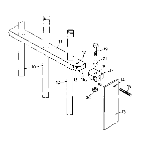
Fig. 1 is an exploded perspective view of a
portion of railing unit, a mounting and blanking spigot
and a support post, and
Figs 2 and 3 are plan views of two alternative
spigots as shown in Fig. 1.
Referring firstly to Fig. 1 of the drawing there
is shown a portion of a fencing unit comprising upright
railing members 10 located through a longitudinally
extending horizontal mounting rail 11. The inner
surface and the upper and lower end surfaces of the
rails 11 are cut away to form arcuate upper and low
surraces lla. Alternatively the cu. away portion could
be provided as a straisht line cut at 5~ between the
inner and ena edges of the upper and lower surfaces at
lla. Apertures 12 are formed through the upper and
lower surraces of rail 11 equidistant from the ends and
sides thereo_.
An uprigh_ support post 13 is ~orm-d with a screw
threadea aperture la to receive a ixing stud 15
therethrough and loca.e within a corresDonding screw
threaded aperture 15 formed in a mounting and blan~ing
s?igot 17. Th- spigot 17 has a planar end surface 17a
and a planar side sur~ace 17b. The other end surface
17c and the other side surface 17d are _ormed to
provide an arcuate surface 17e (Fig. 2) but this could
alternatively be formed as a ~5~ anglec surface 17f
(Fig.3). A notch 17g is formed in side surface 17d
adjacent end sur~ace 17a. An ape;.ure 18 is formed
through spisot 17 so as to be alisnable with apertures
12 in rail 11.
A fixing bolt 19 is locatable through apertures 12
and 18 with nut 20 being tightened to provided the

CA 02221632 1997-ll-l9
WO 96/37670 4 PCT/GB96/01222
~ixing. The aperture 18 may be counter bored and a
cone 21 located on bolt 19 both above and below spigot
17 so that the apertures 12 are deformed when bolt 19
and nut 20 are tightened to provide a tamper-proof
fixing. Additionally or alternatively the upper and
lower surfaces of rail 11 can be deformed at spigot 17
to provided such tamper-proof fixing.
When assembling the parts to provide attachment of
the railing unit to post 13, spigots 17 are attached to
post 13 by fixing studs 15. When the unit is to be
located at an angle to post 13, less than 90~, spigot
17 is attached in the position shown in Fig. 1 so that
when bolt 19 is located through apertures 12 and 18 the
railing unit can be hinged to the required direction
lS and surrace 17e or 17f o~ spigot 17 blanking the gap at
lla of rail 11. When the railing unit is required to
form part o~ a straight line railing assembly of units
the spigot 17 is attached to post 13 in its reverse
position, ro.ated through 180~ to that shown in Fig. 1,
so that surrace 17b blanks the gap rormed at portion
lla or rail '1.
When tk- railing unit is required .o be located at
90~ to an acjacent unit then the post 13 is provided as
a 90~ angle member with each unit being attached to
different angle portions of the post.
In a ty?ical a_rangement with the dimensions of
rails 11 being 25 x SOmm box section the dimensions of
spigot 17 are : 'A' 30mm minimum; 'B' 7mm maximum; 'C'
23.Smm maximum radiusi 'D' 23.Smm maximum and 'E' 25mm
dead centre.
Hence there is provided a single spigot member 17
which can be utilised to provide fixing of railing
units to posts to provide any configuration of railing
assembly.

CA 02221632 1997-ll-lg
W096/37670 5 PcTtGB96/01222
With an alternative ~ixing arrangement the
apertures in rail 11 need not be provided and
alternatively pressure is applied to the upper and
lower surfaces of rail 11 to provide inwardly depending
dimples located in aperture 18 of spigot 17. Hence a
fixing is provided without the need for bolt 19.

Representative Drawing
A single figure which represents the drawing illustrating the invention.
Administrative Status

2024-08-01:As part of the Next Generation Patents (NGP) transition, the Canadian Patents Database (CPD) now contains a more detailed Event History, which replicates the Event Log of our new back-office solution.

Please note that "Inactive:" events refers to events no longer in use in our new back-office solution.

For a clearer understanding of the status of the application/patent presented on this page, the site Disclaimer , as well as the definitions for Patent , Event History , Maintenance Fee  and Payment History  should be consulted.

Event History

Description Date
Inactive: IPC from MCD 2006-03-12
Application Not Reinstated by Deadline 2001-05-22
Time Limit for Reversal Expired 2001-05-22
Deemed Abandoned - Failure to Respond to Maintenance Fee Notice 2000-05-23
Inactive: IPC assigned 1998-02-25
Inactive: First IPC assigned 1998-02-25
Inactive: IPC assigned 1998-02-25
Classification Modified 1998-02-25
Inactive: Notice - National entry - No RFE 1998-02-11
Application Received - PCT 1998-02-10
Application Published (Open to Public Inspection) 1996-11-28

Abandonment History

Abandonment Date Reason Reinstatement Date
2000-05-23

Maintenance Fee

The last payment was received on 1999-05-21

Note : If the full payment has not been received on or before the date indicated, a further fee may be required which may be one of the following

  • the reinstatement fee;
  • the late payment fee; or
  • additional fee to reverse deemed expiry.

Patent fees are adjusted on the 1st of January every year. The amounts above are the current amounts if received by December 31 of the current year.
Please refer to the CIPO Patent Fees web page to see all current fee amounts.

Fee History

Fee Type Anniversary Year Due Date Paid Date
Basic national fee - small 1997-11-19
MF (application, 2nd anniv.) - small 02 1998-05-22 1998-05-22
MF (application, 3rd anniv.) - small 03 1999-05-25 1999-05-21
Owners on Record

Note: Records showing the ownership history in alphabetical order.

Current Owners on Record
DENNIS ARTHUR SUMMERS
Past Owners on Record
None
Past Owners that do not appear in the "Owners on Record" listing will appear in other documentation within the application.
Documents

To view selected files, please enter reCAPTCHA code :


To view images, click a link in the Document Description column. To download the documents, select one or more checkboxes in the first column and then click the "Download Selected in PDF format (Zip Archive)" or the "Download Selected as Single PDF" button.

List of published and non-published patent-specific documents on the CPD .

If you have any difficulty accessing content, you can call the Client Service Centre at 1-866-997-1936 or send them an e-mail at CIPO Client Service Centre.


Document
Description 
Date
(yyyy-mm-dd) 
Number of pages   Size of Image (KB) 
Abstract 1997-11-18 1 50
Description 1997-11-18 5 186
Claims 1997-11-18 3 67
Drawings 1997-11-18 1 19
Representative drawing 1998-02-26 1 5
Reminder of maintenance fee due 1998-02-10 1 111
Notice of National Entry 1998-02-10 1 193
Courtesy - Abandonment Letter (Maintenance Fee) 2000-06-19 1 184
PCT 1997-11-18 13 388
Fees 1998-05-21 1 32
Fees 1999-05-20 1 27