Language selection

Search

Patent 2222011 Summary

Third-party information liability

Some of the information on this Web page has been provided by external sources. The Government of Canada is not responsible for the accuracy, reliability or currency of the information supplied by external sources. Users wishing to rely upon this information should consult directly with the source of the information. Content provided by external sources is not subject to official languages, privacy and accessibility requirements.

Claims and Abstract availability

Any discrepancies in the text and image of the Claims and Abstract are due to differing posting times. Text of the Claims and Abstract are posted:

  • At the time the application is open to public inspection;
  • At the time of issue of the patent (grant).
(12) Patent Application: (11) CA 2222011
(54) English Title: CURLING STONE FOR CURLING WITH CONTINUOUSLY VARIABLE GLIDING CHARACTERISTICS
(54) French Title: PIERRE DE CURLING DEMONTRANT DES CARACTERISTIQUES DE GLISSEMENT A REGLAGE CONTINU
Status: Deemed Abandoned and Beyond the Period of Reinstatement - Pending Response to Notice of Disregarded Communication
Bibliographic Data
(51) International Patent Classification (IPC):
  • A63B 67/14 (2006.01)
(72) Inventors :
  • HERZ, JOSEF PAUL (Austria)
(73) Owners :
  • JOSEF PAUL HERZ
(71) Applicants :
  • JOSEF PAUL HERZ (Austria)
(74) Agent: SMART & BIGGAR LP
(74) Associate agent:
(45) Issued:
(86) PCT Filing Date: 1996-05-22
(87) Open to Public Inspection: 1996-11-28
Availability of licence: N/A
Dedicated to the Public: N/A
(25) Language of filing: English

Patent Cooperation Treaty (PCT): Yes
(86) PCT Filing Number: PCT/AT1996/000097
(87) International Publication Number: WO 1996037268
(85) National Entry: 1997-11-21

(30) Application Priority Data:
Application No. Country/Territory Date
A 857/95 (Austria) 1995-05-22

Abstracts

English Abstract


The present invention relates to an improvement of a curling stone
known from Austrian patent No. 354,921 wherein a support shell (2) provided
with one of more openings (6) for rendering the brake device accessible is
supportively placed between the handle (1) and the housing (3), the support
shell being provided in its upper surface with a central bore. In a preferred
embodiment, the bracket (9) of the brake device is an inherently resilient
support member of star-shaped cross-sectional configuration with preferably
three to six arms (11), radially narrowing slots (18,19) being provided in the
arms (11) for receiving the brake surface supports (15).


French Abstract

Amélioration d'une pierre de curling connue sous le numéro de brevet autrichien 354,921. Une coquille de support (2), présentant une ou plusieurs ouvertures (6) pour rendre le mécanisme de freinage accessible, est placée en appui entre le manche (1) et le boîtier (3), la coquille présentant dans sa surface supérieure un trou central. Selon un modèle préféré, la console (9) du mécanisme de freinage s'avère un support essentiellement élastique de section transversale étoilée et pourvu, de préférence, de trois à six bras (11) présentant des fentes radiales décroissantes (18, 19) servant à recevoir les supports de surface de frein (15).

Claims

Note: Claims are shown in the official language in which they were submitted.

CLAIMS
1. Curling stone for curling, consisting of a handle, a housing for the
support of gliding and braking elements, and a bottom glide plate covering the
bottom side of the housing and optionally provided with gliding bumps, part of
the gliding surface being formed by a brake device the braking surface of
which is affixed to a support for sliding movement in an axial direction of the
curling stone relative to the remaining gliding surface cover and moveable
against spring bias into the housing to adjust the brake action, the brake
device consisting of a plurality of independently moveable brake surface
supports arranged concentrically and symmetrically around the axis of the
curling stone on a common bracket which is axially adjustable to a limited
extent relative to the curling stone, each support being provided with its own
spring suspension, characterized by the fact that a support shell (2) with one
or more openings (6) for rendering the brake device accessible is supportively
placed between the handle (1) and the housing (3), the support shell (2)
being on the upper surface provided with a central bore.
2. Curling stone according to claim 1, characterized by the fact that the
bracket (9) consists of an inherently resilient support part of preferably
star-shaped configuration with preferably three to six arms (11) provided with
radially tapering slots (18, 19) for receiving the brake surface supports (15).
3. Curling stone according to one of the preceding claims, characterized
by the fact that at their upper end the brake surface supports (15) are
provided with a stepped shaft with a convex annular recess (17) to compensate
for axial displacements of the prestressed or resilient arms (11).
4. Curling stone according to one of the preceding claims, characterized

by the fact that the bracket (9) is provided with a central internally threaded
bush (10) into which a threaded spindle (8) provided below the support shell
(2) may be screwed for adjusting the position of the bracket (9), the threaded
spindle being provided with a continuous bore into which a shaft of the handle
(1) is penetrating, and that the threaded free end of the handle shaft is
threaded into the bottom slide plate which at its upper surface marginal area
abuts against a steel ring (4) between the housing (3) and the bottom slide
plate (5), whereby the bottom slide plate (5) is secured to the curling stone
and by mounting the hand wheel (7) under the support shell (2) arranged
between the handle (1) and the upper surface of the housing (3) the bracket
(9) is secured against axial movement within the housing (3).
5. Curling stone according to one of the preceding claims, characterized
by the fact that the handwheel (7) which is preferable structures as a
numerically marked selector disk is at its lower surface provided with round
notches (12) into which drops a spring biased small ball (13,14) provided in
the housing (3), in an indexing manner.

Description

Note: Descriptions are shown in the official language in which they were submitted.


CA 02222011 1997-11-21
Attorney Docket 970241
Curling Stone for Curling with Continuously
Variable Gliding Characteristics
The invention relates to a curling stone for curling, consisting of a
handle, a housing for the support of gliding and braking elements, and a
bottom glide plate covering the bottom side of the housing and optionally
provided with gliding bumps, part of the gliding surface being formed by a
brake device the braking surface of which is affixed to a support for sliding
movement in an axial direction of the curling stone relative to the remaining
gliding surface cover and moveable against spring bias in the housing to
adjust the brake action, the brake device consisting of a plurality of
independently moveable brake surface supports arranged concentrically and
symmetrically around the axis of the curling stone on a common bracket
which is axially adjustable to a limited extent relative to the curling stone,
each support being provided with its own spring suspension.
Such a curling stone may be easily adjusted without further auxiliary
means in accordance with temperature induced changes in the antifrictional
properties of the ice as they occur in practice.
A curling stone of the kind mentioned above is known from Austrian
patent No. 354,921. Even though that curling stone permits satisfactory
adjustments to different gliding properties of ice, it has for several reasons
been found to warrant improvement. Collisions with other curling stones may
lead to unseating of the housing so that the hand wheel for adjusting the
brake device is pressed against the lower flange at the end of the handle and
is blocked, thus making further adjustments of the brake device impossible.
Furthermore, in operation, such major components as handle, housing, and
bottom glide plate with its steel ring may shift, since unlike in conventional

CA 02222011 1997-11-21
curling stones the handle is not threadedly connected to the housing and to
the bottom glide plate. Moreover, the use of coil springs, notwithstanding the
advantages yielded by them, has been found to be disadvantageous as the
brake surface supports cannot be quickly replaced.
Therefore, it is an object of the present invention to provide an im-
provement in the known curling stone to avoid the mentioned disadvantages
which, in particular, make any adjustments of the brake device difficult or
impossible, and to provide for simplified handling, especially as regards the
brake device.
In accordance with the invention, the object is accomplished by
supportively arranging in the known curling stone, between the handle and
the housing, a support shell preferably provided with one or more milled
openings to render the brake device accessible, the support shell being in its
upper surface provided with a central bore.
In another embodiment of the invention, the bracket of the brake
device is an inherently resilient support of preferably star-shaped cross-
section provided with a plurality arms (cantilevers), preferably three to six,
with slots tapering in a radial direction for suspending the individual brake
surface supports. In a further embodiment, the brake surface supports are
20 provided with a stepped shaft provided with a preferably convex annular
recess.
In contrast to the known use of coil springs, this embodiment of the
brake device facilitates handling, in particular a quicker replacement of
possibly worn brake surface supports. To this end, where brake surface
25 supports are provided with stepped shafts, they are inserted into the slots at
the widest portion thereof which is preferably shaped in the manner of a bore,
and after snapping in their annular recess, they are pushed outwardly along
the tapering slot into their final position. When in their idle or relieved state,
the arms (cantilevers) may be slightly prestressed by about 3 mm in the
30 direction of the bottom glide plate.
For setting the initial position of the brake surface supports, it is

CA 02222011 1997-11-21
proposed that the bracket is preferably provided with an internally threaded
bush in which a threaded spindle disposed beneath the support bell may be
threadedly received for positional adjustments. The threaded spindle is pro-
vided with an axial bore into which a shaft of the handle is penetrating, and
S the shaft of the handle is at it threaded free end screwed into the bottom glide
plate the marginal portion of the upper surface of which abuts against a steel
ring disposed between the housing and the bottom glide plate, whereby the
bottom glide plate is affixed to the curling stone and by mounting the hand
wheel below the support shell positioned between the handle and the upper
10 surface of the housing, the bracket is secured against axial displacement in
the housing.
The invention will hereafter be explained in detail with reference to the
drawings.
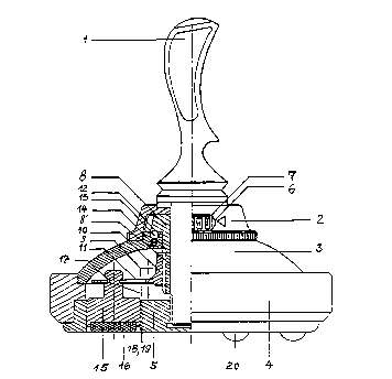
Fig. 1 depicts a curling stone in accordance with the invention in half
15 vertical section.
The curling stone in accordance with the invention consists of a handle
1, a support shell 2 supportively placed between the handle 1 and a housing
3, and of a bottom glide plate 5 connected to a steel ring 4. Instead of being
of the convex configuration depicted in Fig. 1, the housing may also be
20 conical. The support shell 2 is provided with one or more openings 6 which
allow access to a hand wheel 7 preferably formed as a dial with numbered
indicia thereon and being of smaller diameter than the support shell 2. Thus,
no matter how tight it may be, the wheel may be freely rotated on the
threaded shaft of the handle 1 for adjusting the brake device at any time. The
25 hand wheel 7 constitutes the upper portion of a threaded spindle 8 which is
adjustably connected by an external thread 8' to a bracket 9 of preferably
star-shaped cross-section provided with an internally threaded bush 10. The
bracket 9 is provided with a plurality of inherently resilient arms (cantilevers)
11, preferably three to six. At the bottom surface of the hand wheel 7 there
30 are provided round recesses 12 into which a small ball 13 provided in the
housing 3 and biased by a pressure spring 14 may drop in an indexing

CA 02222011 1997-11-21
manner. Preferably, three to six brake surface supports 15 with brake linings
16 seated in their lower surfaces, are arranged in a partial circle on the
inherently resilient arms. At their upper end, the brake lining supports 15 are
provided with a concave annular recess 17 to compensate for axial displace-
5 ments of the prestressed or resilient arms 11. The brake lining supports 15are mounted on the arms 1 1 in radially narrowing slots 18, 19. The curling
stone shown in Fig. 1 is additionally provided with glide bumps 20.
In Figs. 2 and 3, an embodiment of a brake device is shown by way of
example which is provided with three arms or brake surface supports, Fig. 1
10 depicting the brake device in partial section, including the threaded spindleand Fig. 2 depicting a top elevation of the brake device without the threaded
spindle. The reference characters correspond to those of Fig. 1.
To prevent manipulation by third parties, the hand wheel may
additionally by provided with a lock by means of a pressure latch of any
15 desired construction.
Organic and inorganic felt products of any kind and shape (even
brushes) made of various kinds of plastic and rubber or of cork may be used
as brake linings. Silicon rubber of low Shore hardness has proven to be
excellent as a slow lining. By replacement of the bottom glide surface and, if
20 necessary, of the bumps and the brake surface supports, the curling stone in
accordance with the invention may be conventionally converted for use in ice-
free seasons, as for instance, on asphalt surfaces.

Representative Drawing
A single figure which represents the drawing illustrating the invention.
Administrative Status

2024-08-01:As part of the Next Generation Patents (NGP) transition, the Canadian Patents Database (CPD) now contains a more detailed Event History, which replicates the Event Log of our new back-office solution.

Please note that "Inactive:" events refers to events no longer in use in our new back-office solution.

For a clearer understanding of the status of the application/patent presented on this page, the site Disclaimer , as well as the definitions for Patent , Event History , Maintenance Fee  and Payment History  should be consulted.

Event History

Description Date
Application Not Reinstated by Deadline 2000-05-23
Time Limit for Reversal Expired 2000-05-23
Deemed Abandoned - Failure to Respond to Maintenance Fee Notice 1999-05-25
Inactive: First IPC assigned 1998-03-02
Inactive: IPC assigned 1998-03-02
Classification Modified 1998-03-02
Inactive: Notice - National entry - No RFE 1998-02-16
Inactive: Inventor deleted 1998-02-16
Application Received - PCT 1998-02-13
Application Published (Open to Public Inspection) 1996-11-28

Abandonment History

Abandonment Date Reason Reinstatement Date
1999-05-25

Maintenance Fee

The last payment was received on 1998-05-21

Note : If the full payment has not been received on or before the date indicated, a further fee may be required which may be one of the following

  • the reinstatement fee;
  • the late payment fee; or
  • additional fee to reverse deemed expiry.

Please refer to the CIPO Patent Fees web page to see all current fee amounts.

Fee History

Fee Type Anniversary Year Due Date Paid Date
Basic national fee - standard 1997-11-21
MF (application, 2nd anniv.) - standard 02 1998-05-22 1998-05-21
Owners on Record

Note: Records showing the ownership history in alphabetical order.

Current Owners on Record
JOSEF PAUL HERZ
Past Owners on Record
None
Past Owners that do not appear in the "Owners on Record" listing will appear in other documentation within the application.
Documents

To view selected files, please enter reCAPTCHA code :


To view images, click a link in the Document Description column. To download the documents, select one or more checkboxes in the first column and then click the "Download Selected in PDF format (Zip Archive)" or the "Download Selected as Single PDF" button.

List of published and non-published patent-specific documents on the CPD .

If you have any difficulty accessing content, you can call the Client Service Centre at 1-866-997-1936 or send them an e-mail at CIPO Client Service Centre.


Document
Description 
Date
(yyyy-mm-dd) 
Number of pages   Size of Image (KB) 
Description 1997-11-21 4 179
Abstract 1997-11-21 1 19
Claims 1997-11-21 2 73
Drawings 1997-11-21 2 51
Cover Page 1998-04-01 1 51
Representative drawing 1998-04-01 1 12
Reminder of maintenance fee due 1998-02-16 1 111
Notice of National Entry 1998-02-16 1 193
Courtesy - Abandonment Letter (Maintenance Fee) 1999-06-22 1 186
PCT 1998-04-09 5 172
PCT 1997-11-21 13 420
Fees 1998-05-21 1 47