Note: Descriptions are shown in the official language in which they were submitted.
. CA 02222029 1997-11-24
WO 97/37470 PCTIITS97lO5I20
1
SLICE PREDICTOR FOR A SIGNAL RECEIVER
Techn i ca'1 Fi P1 r7 of t-hP riv nt i,,Qg
The present invention relates to a slicing
arrangement for slicing mufti-level signals which are
transmitted and received in a data transmission and
reception system.
gac~_k_qrpLnd c~f f-_~ Tnsrant-inn
Mufti-level modulation, such as the modulation
' produced by trellis encoders,~is a well-known technique
for improving the performance of a data transmission and
reception system. For example, mufti-level modulation
results in an improvement in the signal-to-noise (S/N)
performance of the data transmission and reception system
at a given power level. Alternatively, mufti-level
modulation permits the transmitted power level required
to achieve a given signal-to-noise performance to be
reduced.
In essence, trellis-coded modulation (TCM)
comprises the use of a mufti-state convolution encoder to
convert each k input data bits of an input sequence of
data bits into k+n output data bits, and is therefore
referred to as a rate k/(k+n) convolution encoder. The
output bits are then mapped into a sequence of discrete
mufti-level symbols of a modulated carrier for data
transmission. Each mufti-level symbol typically has one
of 2ik+n~ values. These values can be phase and/or
amplitude values. By coding the input data bits in a
state-dependent sequential manner, increased minimum
Euclidean distances between the allowable transmitted
sequences may be achieved leading to a reduced error
CA 02222029 1997-11-24
V6V0 97/37~i70 PCT/fJS97/OSIZO
2
probability where a maximum likelihood decoder (for
example, a Viterbi decoder) is used in the receiver.
In an example of a data transmission and
reception system which uses mufti-level modulation,
successive pairs of data bits X1, Xa are encoded for
transmission as eight-level, one-dimensional symbols.
More,specifically, bit Xl is convolutionally encoded using
a four-state convolution encoder to generate bits Zo, Z1,
and bit Xa is precoded to generate bit Za. Bits Z2, ZI,
and Zo are mapped to respective eight-level symbols using
a one-dimensional symbol constellation. As an example,
2~~'*n~ amplitude values of -7, -5, -3, -1, +1, +3, +5, and
+7 may be used for the one-dimensional symbol
constellation. The eight-level symbols, after insertion.
of appropriate sync signals, are transmitted in the form
of a suppressed carrier vestigial sideband (VSB) signal.
This signal is received by a receiver which, at
the front end, may include a tuner, an IF demodulator, an
analog-to-digital (A/D) converter, a channel. equalizer,
and a decoder. The decoder decodes the mufti-level
symbols in order to recover the successive pairs of data
bits Xl, Xa. The receiver may also include a phase
tracker to reduce phase noise errors and amplitude-
related errors. That is, many signal receivers, such as
television receivers, which are used in data transmission
and reception systems and which are designed for
receiving suppressed carrier VSB signals, use a double
conversion tuner at the receiver front end. The first
local oscillator of such a tuner typically exhibits a
relatively high level of phase noise in the demodulated
CA 02222029 1997-11-24 _
WO 97!37470 YCTJITS97105120
3
data. In addition, the demodulated data may be degraded
by amplitude-related errors resulting in the demodulated
data being recovered with undesired offsets and/or at
undesired levels of gain. These phase noise errors and
amplitude-related errors may lead to an unacceptable
error rate if uncorrected, especially in the case of
tightly packed data constellations. In order to minimize
the error rate due to phase noise errors and amplitude-
related errors, the mufti-level symbols may be processed
by a phase tracker. An example of such a phase tracker
is disclosed in U.S. Patent No. 5,406,587.
Circuits, such as equalizers and phase
trackers, usually compute a sliced data signal from a
continuous valued signal. The conventional slicer slices
the eight-level symbols.in accordance with a set of seven
slice levels to produce one of eight quantized output
values. While this approach to slicing is perfectly
satisfactory in theory, performance of the conventional
slicer is usually degraded under noisy conditions which
cause the amplitude of a mufti-level symbol level to
cross a slice level solely due to noise acquired during
transmission and reception.
For example, the amplitude of a symbol
originally having a value of +5 (using the -7, -5, -3,
-1, +1, +3, +5, +7 constellation described above) may be
degraded by noise such that its value at the output of
the phase tracker may be +6.1. Accordingly, a slicing
system, which slices the received signal at -6, -4, -2,
0, +2, +4, and +& will produce an incorrect quantized
value of +7 rather than the proper quantized value of +5
CA 02222029 1997-11-24
WO 97/37470 PCT/US97/05120
4
for use by the phase tracker.
The present invention solves one or more of the
above described problems.
~t?mmarv of thr~ Tnyt~nr; nr,
Tn accordance with one aspect of the present
invention, a data processor comprises a receiving means,
a selecting means, and a slicing means. The receiving
means receives a plurality of multi-level symbols. The
selecting means selects one of a plurality of sets of
slice values, wherein each set of slice values has a
minimum of three slice values. The slicing means slices
the multi-level symbols in response to the selected set
of slice values.
In accordance with another aspect of the
' present invention, a data processor comprises a receiving
means, a selecting means, and a slicing means. The
receiving means receives a plurality of mufti-level
symbols. The selecting means selects one of only two
sets of slice values, wherein each of the only two sets
of slice values has a plurality of slice values. The
slicing means slices the mufti-level symbols in response
to the selected set of slice values.
In accordance with yet another aspect of the
present invention, a data processor comprises a receiving
means, a selecting means, and a slicing means. The
receiving meant receives a plurality of mufti-level
symbols. The selecting means selects one of only five
sets of slice values, wherein each of the only five sets
of slice values has a plurality of slice values. The
slicing means slices the mufti-level symbols in response
CA 02222029 1997-11-24
WO 97/37470 PCT/US97/OSI20
to the selected set of slice values.
Zn accordance with a further aspect of the
present invention, a data processor comprises a
developing means, a determining means, a selecting means,
and a slicing means. The developing means develops a
data signal including a plurality of multi-level symbols.
The determining means is responsive to each of the
multi-level symbols in order to determine a lowest path
metric characterizing the data signal. The selecting
means selects one of a plurality of sets of slice values
in response to the lowest path metric. The slicing means
slices the multi-level symbols in response to the
selected set of slice values.
Br. ief De,,gcrirtion of the Drawinc_rs
These and other features and advantages of the
present invention will become more apparent from a
detailed consideration of the invention when taken in '
conjunction with the drawings in which:
Figure 1 is a block diagram of a transmitter
which is useful in a multi-level symbol data transmission
and reception system and which includes a precoder and
trellis encoder;
Figure 2 is a block diagram of a receiver which
is useful in a multi-level symbol data transmission and
reception system and which includes a channel equalizer
and a phase tracker;
Figure 3 is a block diagram illustrating the
precoder and trellis encoder of Figure 1;
Figure 4 is a slicing arrangement which
implements the present invention and which is useful with
CA 02222029 1997-11-24
wo 97r~747o rcT~rs9~~osi2o
6
the channel equalizer and the phase tracker of Figure 2;
Figure.5 illustrates two sets of slice levels
for the slicer shown in Figure 4 in the case where a comb
filter is not used in the receiver of a multi-level
symbol data transmission and reception system;
Figure 6 is a state table illustrating the
operation of the trellis encoding process;
Figure 7 is a trellis diagram for the trellis
encoder of Figure 3 and is based upon Figure 6;
Figure 8 illustrates seven unique co-sets which
characterize the output of a comb filter when used in
conjunction with a multi-level symbol data transmission
and reception system;
Figure 9 illustrates five sets of slice values
' for the slicer shown in Figure 4 in the case where a comb
filter is used in the receiver of a multi-level symbol
data transmission and reception system;
Figure 10 illustrates an alternative two sets
of slice values for the slicer shown in Figure 4 in the
case where a comb filter is used in the receiver of a
mufti-level symbol data transmission and reception
system;
Figures 11-13 illustrate a refinement of the
present invention; and,
Figure 14 is a trellis diagram similar to the
trellis diagram illustrated in Figure 7 but for the case
where a trellis encoder and a comb filter are used in
combination.
Figures 1 and 2 generally illustrate a multi-
CA 02222029 2002-O1-25
- WO 97/37470 . PCT/US97/OSI20
7
level symbol data transmission and reception system as
applied to a multi-level VSB~high definition television
(HDTV) transmission and reception system of the type
disclosed in U.S. Patent No. 5,087,975 and in U.S. Patent No.
5,583,889.
However, while the
multi-level VSB HDTV application is contemplated in the
preferred embodiment of the present invention, it will be
understood that the present invention is more general in
nature and, thus, may be applied to other types of
transmission and reception systems, including lower
resolution video systems as well as non-video based .data
systems.
Accordingly, as.shown in Figure 1, a
transmitter l0 of a multi-level symbol data transmission
and reception system includes a data source 12 which -
provides a succession of data bytes and a plurality of
timing signals. The data bytes, for example, may include
eight bits per byte and may comprise a compressed HDTV
signal, a compressed television signal of NTSC
resolution, or any other data signal.
The data bytes are preferably, although not
necessarily, arranged in successive fields. Each field
includes a field segment and 312 field sync and data
segments, and each field sync- and data segment comprises
828 eight-level symbols and four two-level data segment
sync symbols occurring at a symbol rate of about 10.76.
Msymbols/sec. The data bytes from the data source 12 are
applied to a Reed Solomon encoder 14 for forward error
CA 02222029 1997-11-24
WO 97/37470 PCT/LTS97/05120
8
correction coding, and then to a byte interleaves 16.
The byte interleaves 16 reorders the data bytes
throughout a frame to reduce the susceptibility of the
multi-level symbol data transmission and reception system
to burst noise.
The interleaved data bytes from the byte
interleaves 16 are applied to a symbol interleaves 18
which provides, for example, two output bit streams Xl and
Xa at the symbol rate. As disclosed, each bit pair X,,, x2
is converted'to a corresponding multi-level symbol. In
particular, due to the presence of a comb filter in the
receiver (to be described in more detail hereinafter), it
is desirable to interleave the bit pairs Xl, X2 of each
data segment among twelve subsegments. Therefore, each
' subsegment comprises, far example, 69 symbols. This
symbol interleaving is discussed in more detail in the
aforementioned PCT/US95/08174 application.
The stream of bit pairs Xl, Xa from the symbol
interleaves 18 is coupled to a precoder and trellis
encoder 20 for conversion to three output bits as
described in further detail hereinafter. Because the
precoder and trellis encoder 20 is characterized by a
twelve-symbol delay, the precoder and trellis encoder 20
may be envisioned as comprising twelve parallel encoders
each operating at 1/12 of the symbol clock rate such that
each subsegment generated by the symbol interleaves 18 is
processed by a respective one of twelve parallel
encoders. The stream of three-bit output bits developed
at the output of the precoder and trellis encoder 20 is
applied to a symbol mapper 22 and therefrom to a
CA 02222029 1997-11-24
WO 97/37470 PCT/IlS97lO5I20
.9
multiplexer 23. The multiplexer 23 multiplexes the
output of the mapper 22 with a field sync symbol and a
segment sync symbol. The field sync symbol and the
segment sync symbol provide field structure. The symbols
mapped by the mapper 22, the field sync symbol, and the
segment sync symbol, which are multiplexed by the
multiplexer 23, are connected to a VSB modulator 24 for
transmission as a plurality of multi-level symbols.
As shown in Figure 2, a receiver 26 of the
mufti-level. symbol data transmission and reception system
receives the signal transmitted by the VSB modulator 24
and includes a tuner, demodulator, and A/D converter 28.
The tuner, demodulator, and A/D converter 28 tunes a
desired channel, converts the received and tuned signal
to an intermediate frequency signal, demodulates the
intermediate frequency signal to a baseband analog
signal, and converts the baseband analog signal to a
digital signal for further processing. This digital
signal comprises the stream of mufti-bit, mufti-level
symbols which are transmitted by the transmitter 10, and
is applied by a multiple pole switch 30 to first and
second signal processing paths.
The first signal processing path comprises a
comb filter 32, a channel equalizer 34, a phase
tracker 36, and a Viterbi decoder 38. The second signal
processing path comprises the channel equalizer 34, the
phase tracker 36, a Viterbi decoder 40, and a post coder
42. The output of the Viterbi decoder 38, or the output
of the post coder 42, is connected to a symbol
deinterleaver 44, a byte deinterleaver 46, and a Reed
CA 02222029 1997-11-24
WO 97/37470 PCT/ITS97/05120
Solomon decoder 48. The output of the Reed Solomon
decoder 48 is further processed by elements of the
receiver 26 not shown. The comb filter 32 may comprise a
feed forward filter including a linear summer and a
twelve-symbol delay element.
The reason for these different first and second
signal processing paths is because of the possibility of
co-channel interference. That is, as explained in more
detail in the previously mentioned X975 U.S. patent, the
comb filter 32 is operable for reducing NTSC co-channel
interference by subtracting from each received symbol,
the symbol received twelve-symbol intervals earlier.
Because of the symbol interleaving provided in the
transmitter, the comb filter 32 independently operates on
each of the twelve subsegments of a data segment for
providing successive combed outputs of the form Al-Ao, Bi-
Bp, . . . AZ-Al, B2-Bl, . . . AS6-A55, B56-BSS,
The comb filter 32 is desirable in those
regions which may receive both HDTV digital signals and
standard NTSC signals. For some period of time, at least
some of the same broadcast channels in adjacent or nearby
television service areas are likely to be allocated for
both NTSC transmissions and HDTV transmissions. This
overlapping allocation may result in co-channel
interference where HDTV and NT$C transmissions in nearby
or adjacent television service areas occur on the same
channel. The comb filter 32 is thus intended to reduce
NTSC co-channel interference from a received HDTV signal.
Accordingly, if the receiver 26 is used in such a service
area, the multiple pole switch 30 is operated to process
CA 02222029 1997-11-24
< < WO 97!37470 PCT/US97/QSiZQ
11
the output from the tuner, demodulator, and A/D converter
28 along the first path which includes the comb filter 32
and the Viterbi decoder 38. If the receiver 26 is not
used a.n such a service area, the output of the tuner,
demodulator, and A/D converter 28 may be processed along
the second path which bypasses the comb filter 32 and the
Viterbi decoder 38 and instead processes the signals
using the Viterbi decoder 40 and the post codes 42. The
processing along the second path is simpler because the
comb filter 32 doubles the complexity of processing the
- received data signals.
As shown in Figure 3, the precoder and trellis
encoder 20 includes a precoder 50 and a trellis encoder
52. The precoder 50 is a modulo-2, feedback precoder
which receives the multi-level symbols (each symbol being
identified as bits X1 and X2).from the symbol interleaves
18, and develops intermediate bits Y1, Y2. More
specifically, the precoder 50 includes a modulo-2 summer
54 having a first input connected to receive the bit X2.
The output of the modulo-2 summer 54 provides the
intermediate bit Ya and is oonnected to a first (A) input
of a multiplexes 56 having an output connected to a
twelve-symbol delay element 58. The output of the
twelve-symbol delay element 58 is connected to a second
input of the modulo-2 summer 54 and is also connected to
a second (B) input of the multiplexes 56. The
intermediate bit YZ generated by the precoder 50 is
applied as an output bit Zz to a first input of the symbol
mapper 22. The intermediate bit Yl is an uncoded.form of
the bit Xl and is supplied to the trellis encoder 52.
CA 02222029 1997-11-24
W~ 97/37470 PCT/CTS97/OSI20
12
The trellis encoder 52 comprises a rate 1/2, 4-
state systematic feedback convolution encoder which
converts the intermediate bit Y1 to the output bits Z1 and
Zo. Accordingly, the- trellis encoder 52 includes a signal
path 60 for applying the intermediate bit Yl as the output
bit Zl directly to a second input of the symbol mapper 22.
Also, the trellis encoder 52 includes a modulo-2 summer
62 which receives the intermediate bit Y1 from the signal
path 60 at a first input thereof. The modulo-2 summer 62
has an output connected to a first (A) input of a
multiplexes 64, the output of which is connected to a
twelve-symbol delay element 66. The output of the
twelve-symbol delay element 66 is connected to the symbol
mapper 22, to a second (B) input of the multiplexes 64,
and to a first (A) input of a multiplexes 68. The
twelve-symbol delay element 66 produces a state bit Qo,
which is used to define a state of the trellis encoder 52
at a particular time arid which is provided as the output
bit Zo. The output of the multiplexes 68 is connected to
a twelve-symbol delay element 70 and produces a state bit
Q1, which is also used to define the state of the trellis
encoder 52 at the particular time. The output of the
twelve-symbol delay element 70 is connected as a second
input to the modulo-2 summer 62 and is fed back to a
second (B) input of the multiplexes 68. Because of the
twelve-symbol delay elements 58, 66, and 70, each
subsegment of a data segment is independently processed
by the precoder 50 and the trellis encoder 52. The
multiplexers 56, 64, and 68 are provided to allow for
sync insertion during which times their respective second
CA 02222029 1997-11-24
WO 97/37470 PCT/US97105120
13
(B) inputs are selected. At all other times, the first
(A) inputs of the multiplexers 56, 64, and 68 are
selected.
The output bits Z2, Z1, and Zo are supplied to
the symbol mapper 22. The symbol mapper 22 maps these'
three output bits to a corresponding one of eight signal
levels to form a multi-level symbol. These eight signal
levels are shown in Columns A and B of Figure 5. Column
C of Figure 5 shows the various combinations of the
output bits Za, Zl, Zo. For example, if ZZ = 0, Z1 = l,
and Zo = 1, the mapper 22 maps output bits Z2, Z1, and Zo
to a multi-level symbol of -1. As can be seen from
Figure 5, the eight-level symbols developed at the output
of the symbol mapper 22 are symmetrical about the zero
level. To facilitate signal acquisition by the receiver
26, it is preferable to offset each symbol by a given
amount (for example, +1 unit) in order to provide a pilot '
component. The multi-level symbols, and the pilot
component if used, are then applied through a first input
of a multiplexes 23 to the VSB modulator 24. The VSB
modulator 24 modulates the mufti-Level symbols (and the
pilot component) on a selected carrier for transmission
in a suppressed carrier VSB form as described in the
previously mentioned '975 U.S. patent. The output of the
symbol mapper 22 is also applied to the input of a R.AM 74
whose output is supplied to a second input of the
multiplexes 23. A third input of the multiplexes 23 is
supplied from a source 76 of segment and frame sync
signals.
Also, as shown in Figure 5, the eight levels of
CA 02222029 2002-O1-25
WO 97/37470 PCT/US97/05120
14
the mufti-level symbols are divided into four subsets a,
b, c, and d. Each of these four subsets is identified by
a particular state of the output bits Zl, Zo. Thus, when
the output bits Z1, Zo are in state 00, their state
corresponds to subset d; when the output bits Zl, Zo are
in state 01, their state corresponds to subset b; when
the output bits Zl, Zo are in state 10, their state
corresponds to subset b; and, when the output bits Zl, Zo
are in state 11, their state corresponds to subset a.
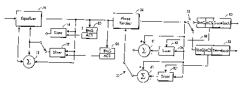
Figure 4 illustrates a modification of a
portion of the receiver 26 shown in Figure 2 according to
the present invention. As illustrated in Figure 4, the
stream of received mufti.-level symbols (at a rate equal
to 10.76 MHz) representing the output bits Z2, Zl, Zo is
provided to the channel equalizer 34. The mufti-level
symbols are equalized by the channel equalizer 34, and
axe then processed by the phase tracker 36 to remove
undesired phase noise. The phase tracker 36 may be of y
the type disclosed in the aforementioned '587 U.S.
patent.
When processing by the comb filter 32 is not
necessary, the output of the phase tracker 36 is
connected through a pole of the multiple pole switch 30
to the Viterbi decoder 40 to derive an estimation of the
original data bits Xl, XZ. As discussed in the
aforementioned U.S. Patent No. 5,583,889 , a Viterbi
decoder, such as a Viterbi decoder manufactured by LST
Logic Corp., includes a branch metric generator (BMG)
which is responsive to the received mufti-level symbols
for generating and for applying branch metrics to wn add,
CA 02222029 1997-11-24
WO 97137470 PCTlUS9~/05I20
compare, and select (ACS) unit. The ACS unit is bi-
directionally coupled to a path metric storage memory
(not shown) and also supplies a traceback memory.
The ACS unit of a Viterbi decoder is responsive
to the branch metrics generated by the BMG for generating
a plurality of path metrics for each multi-level symbol.
Each path metric corresponds to a selected state of a
convolution encoder. The convolutional encoder used in
the present invention (i.e.,.the trellis encoder 52) has
four states as shown by the QlQo(n) column of the state
table shown in Figure 6. Each of these four states is
repeated four times because of the four possible states
of the intermediate bits Yl, Y2 shown in the YaYl (n) column
of Figure 6. , The ZaZlZo (n) column is derived from the
QlQo(n) column and the YaYl(n) column. That is, as shown
in Figure 3, the output bit ZZ is always equal to the
intermediate bit Ya, the output bit Zl is always equal to '
the intermediate bit Yl, and the output bit Zo is always
equal to the state bit Qo. The subset(n) column shows in
which of the four subsets {a, b, c, or d~ a point lies.
The R(n) column is determined by mapping of the Za, Z1, Zo
bits to an output data level. The next state QlQo(n + 1)
is defined by the combination of the current state QlQo(n)
and the current input bit Y1(n).
The information in the state table of Figure 6
may also be represented by the trellis diagram of Figure
7. As shown therein, the four path metrics maintained by
the ACS unit correspond to the four encoder states. As
shown in Figures 5, 6, and 7, when the encoder is in
state 00 or state 10, the symbol output during the
CA 02222029 1997-11-24
~0 9v3~a~o rcT~rs9~iosxzo
16
current symbol period lies in either subset b or subset
d, and when the encoder is in state O1 or state 11, the
symbol output during the current symbol period lies in
either subset a or subset c. Furthermore, the path
metric having the lowest value provides the best estimate
of the current state of the encoder. That is, the lowest
path metric generated by the ACS unit provides an
estimate of the current state of the encoder, and allows
a prediction of which subset the following symbol will
lie in.
As discussed above, a sliced signal is
determined for the channel equalizer 34 based upon its
output as shown in Figure 4, and a sliced signal is
determined for the phase tracker 36 based upon its output
' as shown in Figure 4. The slicing may be accomplished
using a conventional sliver characterized by a single set
of seven slice levels for slicing the eight-level
symbols. The seven levels are shown in Column E of
Figure 5. Thus, a symbol having a level more positive
than +6 would be fed back to the channel equalizer 34 or
the phase tracker 36 as the quantized value +7, a symbol
having a level between +4 and +6.would be fed back as the
quantized value +5, a symbol having a level between +2
and +4 would be fed back as the quantized value +3, a
symbol having a level between 0 and +2 would be fed back
as the quantized value +1, a symbol having a level
between 0 and +2 would be fed back as the quantized value
+1, a symbol having a level between 0 and -2 would be fed
back as the quantized value -1, a symbol having a level
between -2 and -4 would be ted back as the quantized
CA 02222029 1997-11-24
WO 97!37470 PCTIUS97/05I20
17
value -3, a symbol having a level between -4 and -6 would
be fed back as the quantized value -5, and a symbol
having a level below between -6 would be fed back as the
quantized value -7.
While this approach is perfectly satisfactory
in theory, its performance may be degraded under noisy
conditions where the amplitude of the symbol level may
cross a slice level solely due to noise acquired during
transmission and reception. In the example discussed
above, the amplitude of a symbol originally having a
value of +5 may be degraded by noise such that its value
at the output of the phase tracker 36, or at the output
of the channel equalizer 34, is +6.1. Without noise, the
a-5 symbol is correctly sliced by the conventional slicer
to its proper quantized value of +5. However, in the
presence of noise, the +5 symbol is improperly sliced by
the conventional slicer to wn incorrect quantized value
of +7.
Accordingly, unlike conventional slicers, the
slicers of the present invention store plural sets of
slice levels for the purpose explained below. One of
these slicers, a slicer 78 (Figure 4), is used in
conjunction with the channel equalizer 34. The slicer 78
provides an output (through the switch 30) to both the
channel equalizer 34 and a negative input of a summer 79,
and receives an input not only from the output of the
channel equalizer 34, but also from an ACS unit of a
partial Viterbi decoder 80. (For example, the channel
equalizer 34 may be of the type having a feedback filter
and a training algorithm so that the output of the slicer
CA 02222029 1997-11-24
W~ 97/37470 PCT/US97/05120
18
78 is provided to the feedback filter and the output of
the summer 79 is provided to the training algorithm.)
The output of the equalizer 34 is also connected to the
positive input of the summer 79. Only the ACS unit and
the BMG of a Viterbi decoder are required for the partial
Viterbi deCOder 80. Similarly, instead of a conventional
sliver, a sliver 82 is used in conjunction with the phase
tracker 36. The sliver 82 has a symbol input 84, which
is connected to an output of the phase tracker 36, a set
selecting input 86, which,is connected to an ACS unit of
the Viterbi decoder 40, and an output, which is connected
to a negative input of a summer 87. A positive input of
the summer 87 is connected to the symbol input 84. The
output of the summer 87 is connected through another pole
' of the multiple pole switch 30 to the phase tracker 36.
If the phase tracker 36 is the phase tracker disclosed in
the aforementioned '587 U.S. patent, the sliver 82 would
be incorporated in the mapper 34 disclosed therein. The
slivers 78 and 82 are active when the comb filter 32 is
not active.
The sliver 82, which is used with the summer
87, with the phase tracker 36, and with the Viterbi
decoder 40, stores two sets of three slicing levels. One
set of three slicing levels is illustrated in Column F of
Figure 5 and is used by the sliver 82 when the lowest
value path metric supplied by the ACS unit of the Viterbi
decoder 40 corresponds to an encoder state of O1 or 11.
The other set of three slicing levels is illustrated in
Column G of Figure 5 and is used by the sliver 82 when
the lowest value path metric supplied by the ACS unit of
CA 02222029 1997-11-24
t WO 97!37470 PCT/US9'7/OSI20
19
the Viterbi decoder 40 corresponds to aiz encoder state of
00 or Z0.
In other words, if the lowest value path metric
of the ACS unit of the Viterbi decoder 40 corresponds to
an encoder state of O1 or 11, it is assumed that the
multi-level symbol at the output of the phase tracker 36
belongs to either the subset a or the subset c so that
only the three slice levels 88, 90, and 92 in Column F of
Figure 5 need to be used to derive the corresponding
quantized level. Thus, if the multi-level symbol at the
output of the phase tracker 36 and applied to the slicer
82 is more positive than +5, this multi-level symbol will
be quantized to a value of +7. If the mufti-level symbol
is between +5 and +1, this mufti-level symbol will be
quantized to a +3. If the mufti-level symbol is between
+1. and -3, this mufti-level symbol will be quantized to
value of -1. If the mufti-level symbol is more negative
than -3, this mufti-level symbol will be quantized to a
value of -5.
Similarly, if the lowest path metric
corresponds to an encoder state of 00 or 10, it is
assumed that the mufti-level symbol belongs to either
subset b or subset d, so that only the three slice levels
in Column G of Figure 5 is used to derive the quantized
data level to be supplied by the slicer 82 to the summer
87 as discussed above in connection with Column F. Thus,
if the mufti-level symbol at the output of the phase
tracker 36 and applied to the slicer 82 is more positive
than +3, this mufti-level symbol will be quantized to a
value of +5. If the mufti-level symbol is between -1 and
CA 02222029 1997-11-24
WAD 97!37470 , PCT/L1S97/05120
+3, this multi-level symbol will be quantized to a +1.
If the multi-level symbol is between -5 and -1, this
multi-level symbol will be quantized to value of -3. If
the mufti-level symbol is more negative than -5, this
mufti-level symbol will be quantized to a value of -7.
Whether using Column F or Column G, the
distance between adjacent slice levels is twice that of
the conventional slice levels of Column E, thereby
significantly increasing the robustness of the slicing
system. In the example discussed above of a nominal +5
level symbol which has been corrupted by noise to a +6.1
level symbol, the symbol will be quantized to a value of
+7 instead of its correct value of +5 without the present
invention. However, with the present invention, the
' proper result is produced because the lowest path metric
produced by the ACS unit of the Viterbi decoder 40
directs use of the proper slice levels, i.e. the set of
slice levels in Column G.'
The summer 87 subtracts the quantized value
produced by the slicer 82 from the mufti-level symbol at
the output of the phase tracker 36 in order to generate
an error signal which is applied to appropriate elements
of the phase tracker 36.
The slicer 78 associated with the equalizer 34
may operate in a manner which is similar to the slicer
82.
The transfer characteristic of the operation of
the slicer 82 and the summer 87 is shown in Figure 11
which illustrates three exemplary slice values of -3, +1,
and +5. If the slice value, as dictated by the lowest
CA 02222029 1997-11-24
r
WO 97/37470 PCT/US97/05120
21
path metric produced by the ACS unit of the Viterbi
decoder 40, and the output of the phase tracker 36 are
both +5, for example, a zero error value is generated.
If the slice value is +5 and the output of the phase
tracker 36 is +5.5, an error value of +0.5 is generated,
and so on. If the phase tracker 36 is the phase tracker
disclosed in the aforementioned '587 U.S. patent, the
mapper 34 disclosed in this patent uses this error value
to generate its difference.
However, if data (e. g., the output of the phase
tracker 36) is close to midway between two slice values
(such as at about +3), such data can be incorrectly
sliced because there is an uncertainty as to whether the
data should be sliced to a value of +1 or +5. Incorrect
slicing can result in an error and an attempted
correction in the wrong direction. Tn such
circumstances, it may be better to generate a weighted
error signal so that small corrections are attempted in
the region where the slice decisions are likely to be
incorrect rather than possibly correcting in the wrong
direction. In order to correctly generate a weighted
error signal in these circumstances, the slicer 82 and
summer 87 may be combined into a single error look-up
table to produce any desired response, such as the
response illustrated in Figure 12. As shown in Figure
12, an error signal of zero is generated midway between
slice values. Error signals at other data values are
likewise modified in accordance with the characteristic
of Figure 12.
A preferred technique for implementing the
CA 02222029 1997-11-24
WO 97/37470
PCT/US97/05120
22
characteristic of Figure l2 is to use an error LUT 100,
as shown in Figure 13, in place of a slicer and its
corresponding summer. The error LUT l00 stores multiple
look-up tables in which the active look-up table a.s
selected in response to the lowest path metric produced
by the ACS unit of the Viterbi decoder 40. Thus, each
value of the input data addresses a memory location in
the selected look-up table, and the error stored at that
. memory location is read out as the corresponding error
signal.
The above description of=the sliver 82, which
operates in conjunction with the Viterbi decoder 40,
applies to the case where data processing is performed
along the second signal processing path of the receiver
26, i.e. where the comb filter 32 is not used to process
data. However, in the case where data processing is
performed along the first signal processing path of the
receiver 26, i.e. where the comb filter 32 is used to
process data, a sliver 82' having a set selecting input
connected to the ACS unit of the Viterbi decoder 38 is
used instead of the sliver 82. When the multiple pole
.switch 30 is operated so that data is processed along the
first signal processing path, the sliver 82' is active.
The output of the sliver 82' is connected to a summer 83,
which operates in a manner similar to the summer 87.
Similarly, the output of a sliver 78' is connected to a
summer similar to the summer 87, and a partial Viterbi
decoder 94, similar to the partial Viterbi decoder 80, is
used in conjunction with the sliver 78'.
Although the comb filter 32 has the desired
CA 02222029 1997-11-24
WO 97/37470 PCT/US9?!05!20
23
effect of reducing NTSC channel interference, the comb
filter 32 also increases the .complexity of the receiver's
viterbi decoders. That is, an optimum Viterbi decoder
must take into account not only the state of the trellis
encoder 52, but also the state of the delay element of
the comb filter 32. Because there are four encoder
states for the trellis encoder 52, and four possible
states of the delay element of the comb filter 32, an
optimum Viterbi decoder must process a sixteen-state
trellis. The aforementioned PCT/US95/08174 application
illustrates a technique for reducing the complexity of a
Viterbi decoder which is to be used in conjunction with a
comb filter. Such a reduced complexity Viterbi decoder
may be used for the Viterbi decoder 38 and the partial
Viterbi decoder 94.
Each of the BMGs of the Viterbi decoder 38 and
the partial Viterbi decoder 94 generate seven branch
metrics. Each of the seven branch metrics represents the
squared Euclidean distance between the symbol level at
the output of the comb filter 32 and the nearest one of
three values of each of seven co-sets A, B1, B2, C1, C2,
DZ, and D2. These co-sets, and the three values for each
co-set (shown as black dots), are illustrated in Figure 8
hereof .
These co-sets illustrated in Figure 8 may be
re-arranged as shown in Figure 9 according to the
following explanation. When the trellis encoder 52 is in
a particular state, its output can lie in only two of the
four subsets as illustrated in Figure 7. For example,
when the trellis encoder 52 lies in state 00, the next
CA 02222029 1997-11-24
WO 97/37470 PCT/US97/05120
24
symbol must reside in either the subset b or d. The
current estimate of the state of the trellis encoder 52
of the Viterbi decoder 40 can be used to predict in which
of these two subsets the next symbol can lie. Hence, the
slicer 82 can quantize the signal to one of four
amplitudes that make up subset b and/or subset d.
A similar procedure occurs when the comb filter
32 is active. Zt can be shown from Figure 14 that, when
the combination of the trellis encoder 52 and the comb
filter 32 is in a particular state,' the output of the
comb filter 32 will lie in one of only two of the seven
subsets illustrated in Figure 8. (Figure 14 is
reproduced from the aforementioned PCT/US95/08174
application and is a trellis diagram for the case where
the comb filter 32 is active.) Thus, (i) when the
combined state of the, trellis encoder 52 and the comb
filter 32 is state 0, the next symbol must lie in either
subset A or subset C2, (ii) when the combined state of
the trellis encoder 52 and.the comb filter 32 is state 1,
the next symbol must lie in either subset A or subset C1,
(iii) when the combined state of the trellis encoder 52
and the comb filter 32 is state 2, the next symbol, must
lie in either subset B2 or subset D2, (iv) when the
combined state Qf the trellis encoder 52 and the comb
filter 32 is state 3, the next symbol must lie in either
subset B1 or subset D2, (v) when the combined state of
the trellis encoder 52 and the comb filter 32 is state 4,
the next symbol must lie in either subset B1 or subset
D1, (vi) when the combined state of the trellis encoder
52 and the comb filter 32 is state 5, the next symbol
CA 02222029 1997-11-24
t WO 97/37470 . PCT/CTS97/05120
must lie in either subset B1 or subset D2, (vii) when the
combined state of the trellis encoder 52 and the comb
filter 32 is state 6, the next symbol must Iie in either
subset A or subset C1, and (viii) when the combined state
of the trellis encoder 52 and the comb filter 32 is state
7, the next symbol must lie in either subset A or subset
C2.
It is noted that the output co-sets (A and C2)
of transitions (i) and (viii) are the same, that the
output co-sets of transitions (ii) and (vii) are the
same, and that the output co-sets of transitions (iv) and
(vi) are the same. Consequently, these seven co-sets may
be rearranged into five groups of two co-sets each such
that, for a particular state of the trellis encoder
20/comb filter 32 combination, the output of the comb
filter 32 must lie within one of these five groups. The
state of the trellis encoder 52 and the comb filter 32 as '
estimated by the Viterbi decoder 38 can be used to
predict in which of these five groups the next symbol can
lie.
These five groups are shown in Figure 9. Each
group has five slice levels. The five slice levels of
the group A and C2 is shown in Figure 9. Similarly, the
group A and C1 has slice levels at +6, +2, -2, -6, and
-10, the group B2 and D2 has slice levels at +12, +8, +4,
0, and -4, the group B1 and D2 has slice levels at +8,
+~, 0, -4, and -8, and the group B1 and Dl has slice
levels at +4, 0, -4, -8, and -12. Accordingly, the
lowest path metric produced by the ACS unit of the
Viterbi decoder 38 selects the slice levels of one of the
CA 02222029 1997-11-24
i~VO 97/37470
PCT/US97/05120
26
five groups illustrated in Figure 9. The selected set of
slice levels is then used by the slicer 82' for slicing
the output of the phase tracker 36 to produce a quantized
value for supply to the summer 83 or by the slicer 78'
for slicing the output of the equalizer 34.
The five sets of slice levels shown in Figure 9
can be reorganized into two sets of slice values as shown
in Figure 10. These two sets of slice levels shown in
Figure 10 are somewhat less robust than the five sets
illustrated in Figure 9, but these two sets result in a
less complicated selection process. The first set of
slice values, A, C1, and C2, has six slice levels, and
the second set of slice values, B1, B2, D1, and D2, has
seven slice levels. The slicers 78' and 82' store the
seven groups of slice levels shown in Figure 8, the five
groups of slice levels shown in Figure 9, or the two
groups of slice levels shown in Figure 10, as
appropriate.
With these.stored slice levels, the slicer 82'
then responds to the lowest path metric from the ACS unit
of the Viterbi decoder 38 in the same manner as the
slicer 82 responds to the ACS unit of the Viterbi decoder
40, and the slicer 78' responds to the lowest path metric
from the ACS unit of the partial Viterbi decoder 94 in
the same manner as the sliver 82 responds to the ACS unit
of the Viterbi decoder 40. Similarly, the sliver 78
responds to the lowest path metric from the ACS unit of
the partial Viterbi 80 in the same manner as the sliver
82 responds to the ACS unit of the Viterbi decoder 40.
Certain modifications of the present invention
CA 02222029 1997-11-24
WO 97/37470 PCT/US97/051211
27
have been discussed above. Other modifications will
occur to those practicing in the art of the present
invention. The trellis encoder 52, for instance, may
take various other forms than that shown in Figure 3
without departing from the invention. For example, the
number of encoder states may differ from that shown,
feedforward architectures may be used rather than the
disclosed feedback structure, and non-systematic coding
may be employed in either a feedback or a feedforward
arrangement.
Also, modulation and demodulation techniques
other than VSB, such as those employing, for example,
quadrature amplitude modulation (QAM) and demodulation,
may be employed.
Additionally, the present invention has been
described in connection with eight-level symbols,
although it should be understood that the present
invention may be used with symbols having any number of
levels.
Accordingly, the description of the present
invention is to be construed as illustrative only and is
for the purpose of teaching those skilled in the art the
best mode of carrying out the invention. The details may
be varied substantially without departing from the spirit
of the invention, and the exclusive use of all
modifications which are within the scope of the appended
claims is reserved.