Language selection

Search

Patent 2222368 Summary

Third-party information liability

Some of the information on this Web page has been provided by external sources. The Government of Canada is not responsible for the accuracy, reliability or currency of the information supplied by external sources. Users wishing to rely upon this information should consult directly with the source of the information. Content provided by external sources is not subject to official languages, privacy and accessibility requirements.

Claims and Abstract availability

Any discrepancies in the text and image of the Claims and Abstract are due to differing posting times. Text of the Claims and Abstract are posted:

  • At the time the application is open to public inspection;
  • At the time of issue of the patent (grant).
(12) Patent Application: (11) CA 2222368
(54) English Title: INTERNAL COMBUSTION ENGINE HAVING A LPG FEEDING SYSTEM
(54) French Title: MOTEUR A COMBUSTION INTERNE DOTE D'UN SYSTEME D'ALIMENTATION EN GPL
Status: Deemed Abandoned and Beyond the Period of Reinstatement - Pending Response to Notice of Disregarded Communication
Bibliographic Data
(51) International Patent Classification (IPC):
  • F02M 21/02 (2006.01)
  • F02B 69/04 (2006.01)
  • F02D 19/02 (2006.01)
  • F02D 19/06 (2006.01)
  • F02D 41/30 (2006.01)
(72) Inventors :
  • GOZZELINO, RICCARDO (Italy)
  • AUDISIO, FILIPPO (Italy)
  • FERRERA, MASSIMO (Italy)
  • GIANOTTI, PIETRO (Italy)
  • LOMBARDO, GAETANO (Italy)
(73) Owners :
  • C.R.F. SOCIETA CONSORTILE PER AZIONI
(71) Applicants :
  • C.R.F. SOCIETA CONSORTILE PER AZIONI (Italy)
(74) Agent: MACRAE & CO.
(74) Associate agent:
(45) Issued:
(22) Filed Date: 1997-11-27
(41) Open to Public Inspection: 1998-06-04
Examination requested: 1997-11-27
Availability of licence: N/A
Dedicated to the Public: N/A
(25) Language of filing: English

Patent Cooperation Treaty (PCT): No

(30) Application Priority Data:
Application No. Country/Territory Date
TO96A000983 (Italy) 1996-12-04

Abstracts

English Abstract


A LPG injection system for an internal combustion
engines comprises a return conduit (6) which takes the
LPG fed in excess to the injectors (2) back to the tank
(5). In the return conduit (6) there is not interposed
any pressure regulator. Furthermore this conduit (6)
ends with a non-return valve (7) which prevents a flow
within conduit (6) towards the rail (1) for feeding the
LPG to the injectors (2).


French Abstract

L'invention concerne un système d'injection de GPL pour moteur à combustion interne comprenant un conduit de retour (6) qui ramène au réservoir (5) le GPL acheminé en trop aux injecteurs (2). Il n'y a dans le conduit de retour (6) aucun régulateur de pression. De plus, ce conduit (6) se termine par un clapet de non-retour (7) qui empêche l'écoulement dans le conduit (6) vers le rail (1) pour alimenter les injecteurs (2) en GPL.

Claims

Note: Claims are shown in the official language in which they were submitted.

CLAIMS
1. Internal combustion engine having a LPG feeding
system, wherein said system comprises:
- a plurality of injectors (2) respectively
associated with the various cylinders of the engine,
- a feeding manifold or "rail" (1) for feeding
LPG to the injectors (2),
- a LPG tank (5),
- means for feeding LPG from the tank (5) to the
feeding rail (1) while keeping the LPG substantially at
a liquid state, said means including a pump (4) which
feeds LPG from the tank to the rail,
- a return conduit (6) for taking the portion of
LPG fed in excess to the injectors (2) back to the tank
(5),
- sensor means (9) for sensing the pressure of the
LPG fed to the injectors (2), and
- electronic control means for receiving signals
coming from said sensor means (9) for sensing the
pressure of LPG fed to the injectors (2) and
controlling the injector activation time accordingly,
characterized in that said return conduit (6) is
not provided with any pressure regulator and
communicates with said tank through a non-return valve
(7) adapted to prevent a flow within this conduit (6)
towards said rail (1).
2. Internal combustion engine according to claim
1, adapted to operate selectively with gasoline or LPG,
characterized in that said electronic control means
comprises a first electronic control unit (10) of the
type conventionally used in gasoline injection systems,
for controlling the gasoline injection, and a second
electronic control unit (11) adapted to modify the mode
of operation of said first electronic control unit
according to the LPG feeding characteristics, in order
- 6 -

that said first control unit also controls the LPG
injections.
- 7 -

Description

Note: Descriptions are shown in the official language in which they were submitted.


CA 02222368 1997-11-27
Internal combustion engine having a LPG feeding
system
The present invention relates to an internal
combustion engine having a LPG feeding system, wherein
said system comprises:
- a plurality of injectors respectively associated
with the various cylinders of the engine,
- a feeding manifold or rail for feeding LPG to
the injectors,
- a tank which can be filled with LPG,
- means for feeding LPG from the tank to the
feeding rail while keeping the LPG substantially at a
liquid state, said means including a pump for feeding
LPG from the tank to said rail,
- a return conduit for taking the portion of LPG
fed in excess to the injectors back to the tank,
- sensor means for sensing the pressure of the LPG
fed to the injectors, and
- electronic control means for receiving signals
coming from said sensor means for sensing the pressure
of the LPG fed to the injectors and controlling the
injector activation time accordingly.
A system of the above indicated type is disclosed
in Italian patent application TO95A000064 as well as in
the parallel European patent application EP-A-0 725 208
of the same applicant.
- The above mentioned documents relate to an
internal combustion engine adapted to operate
selectively either with gasoline or with LPG and
provided with two separate systems for feeding gasoline
and LPG, in which the LPG feeding system has the above
indicated features.
Yet in the solution previously proposed by the
same applicant, the above mentioned electronic control

CA 02222368 1997-11-27
means comprises a first electronic control unit of the
type conventionally used in gasoline injection system,
for controlling the gasoline injection, and a second
electronic control unit adapted to modify the mode of
operation of the first electronic control unit as a
function of the LPG feeding characteristics, for
controlling the LPG injection by means of said first
electronic control unit.
Yet in the above mentioned previous solution
proposed by the applicant, in the aforesaid return
conduit there is interposed a pressure regulator, for
throttling this conduit so that said pump generates a
pressure increase from the pressure of LPG within the
tank up to the pressure at which the LPG is fed to the
injectors. With this pressure regulator there are
associated means adapted to detect the pressure of the
LPG within the tank, which is a function of the
temperature, as well as to vary the degree of the
throttling of the regulator accordingly, so as to keep
the above mentioned pressure increase at a
substantially constant level, which for instance may be
of Z-3 bars. In this manner, whichever is the
temperature of the LPG tank, the feeding pressure of
the LPG to the injectors is always within the pressure
range at which the injectors operate properly. Indeed,
at very low temperatures (such as -20~C) at which the
LPG pressure is of about 1 bar, the feeding pressure
becomes of the order of 3-4 bars, whereas at high
temperatures (50 C), at which the LPG pressure is of
about 20 bars, the feeding pressure becomes of about
22-23 bars, the pressure range at which the
conventional injectors operate properly being from 3 up
to 23 bars.
While testing the feeding system which has formed
the subject of the above mentioned previous

CA 02222368 1997-11-27
application, the applicant has found however that the
use of the above mentioned pressure regulator may give
origin, in some cases, to engine malfunctions,
particularly to the incapability of starting the engine
again after a stop due to formation of steam bobbles
within the regulator.
The object of the present invention is that of
improving the previously proposed system while
overcoming this drawback.
In view of achieving this object, the invention
provides an engine of the above indicated type,
characterized in that the above mentioned return
conduit is not provided with any pressure regulator and
is connected to the tank through a non-return valve
adapted to prevent a flow within this conduit towards
the LPG feeding rail.
The elimination of the pressure regulator does not
give origin to any drawback, both because the injectors
presently available now operate in a vary broad range
(from 2 to 23 bars) and due to the adoption of said
non-return valve at the tank. It is still to be noted
that, although the elimination of the pressure
regulator implies that operation with a constant
pressure increase is not possible, this does not cause
any inconvenience in the engine operation, since the
pressure sensor downstream of the feeding pump attends
to informing the electronic control unit about the LPG
feeding pressure, so as to enable the engine to be
regulated in the best possible way at any operating
condition. At the same time, the elimination of the
pressure regulator obviously provides a great
simplification and a reduction in cost.
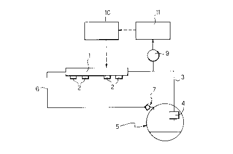
The invention will be now described with reference
to the annexed drawing, given purely by way of non
limiting example, which shows a diagram of the LPG

CA 02222368 1997-11-27
feeding system of the engine according to the
invention
With reference to the figure, numeral 1 generally
designates the manifold or ''rail" for feeding LPG to
four injectors 2 which are respectively associated with
the four cylinders of a motor-vehicle internal
combustion engine. The engine is provided with an
injection feeding system adapted to operate selectively
either with gasoline or LPG. In the drawing, the parts
of the gasoline feeding system have not been
illustrated, since this system is of a conventional
type with gasoline injection, with an electronic
control unit able to control the gasoline injection as
a function of the various operative parameters of the
system.
LPG is fed to rails 1 by means of a conduit 3 by a
feeding pump 4 which draws LPG from a tank 5.
Preferably, pump 4 is located within the tank 5. The
portion of LPG which si fed in excess to the injectors
2 returns to tank 5 through a return line 6 in which
there is not interposed any pressure regulator.
However, line 6 ends with a non-return valve 7 adapted
to prevent a flow within conduit 6 towards manifold 1.
Numeral 10 generally designates the main
electronic control unit which controls operation of the
injectors 2.
During operation of the engine, sensor 9 informs
the control unit 10 about the LPG feeding pressure,
which is a function of the temperature, so as to enable
the injector activation time to be adjusted as a
consequence. The elimination of the pressure regulator
which was present in the previously proposed system
obviously eliminates any risk of an engine malfunction
due to the formation of steam bubbles within the
regulator.

CA 02222368 1997-11-27
As in the previously proposed system, the
activation time of injectors 2 is controlled by the
conventional electronic control unit 10 which is
provided for the gasoline injection system. In this
case, however, the mode of operation of the control
unit is modified by an auxiliary control unit 11,
according to the LPG feeding characteristics.
As already indicated above, the gasoline feeding
rail is separate from the LPG feeding rail, so as to
avoid any complications in the system.
Naturally, while the principle of the invention
remains the same, the details of construction and the
embodiments may widely vary with respect to what has
been disclosed by way of the example, without departing
from the scope of the present invention.

Representative Drawing
A single figure which represents the drawing illustrating the invention.
Administrative Status

2024-08-01:As part of the Next Generation Patents (NGP) transition, the Canadian Patents Database (CPD) now contains a more detailed Event History, which replicates the Event Log of our new back-office solution.

Please note that "Inactive:" events refers to events no longer in use in our new back-office solution.

For a clearer understanding of the status of the application/patent presented on this page, the site Disclaimer , as well as the definitions for Patent , Event History , Maintenance Fee  and Payment History  should be consulted.

Event History

Description Date
Inactive: IPC from MCD 2006-03-12
Application Not Reinstated by Deadline 2000-11-27
Time Limit for Reversal Expired 2000-11-27
Deemed Abandoned - Failure to Respond to Maintenance Fee Notice 1999-11-29
Application Published (Open to Public Inspection) 1998-06-04
Inactive: Single transfer 1998-03-23
Inactive: IPC assigned 1998-03-06
Inactive: First IPC assigned 1998-03-06
Classification Modified 1998-03-06
Inactive: Courtesy letter - Evidence 1998-02-24
Filing Requirements Determined Compliant 1998-02-18
Inactive: Filing certificate - RFE (English) 1998-02-18
Inactive: Inventor deleted 1998-02-18
Application Received - Regular National 1998-02-18
All Requirements for Examination Determined Compliant 1997-11-27
Request for Examination Requirements Determined Compliant 1997-11-27

Abandonment History

Abandonment Date Reason Reinstatement Date
1999-11-29

Fee History

Fee Type Anniversary Year Due Date Paid Date
Request for examination - standard 1997-11-27
Application fee - standard 1997-11-27
Registration of a document 1998-03-23
Owners on Record

Note: Records showing the ownership history in alphabetical order.

Current Owners on Record
C.R.F. SOCIETA CONSORTILE PER AZIONI
Past Owners on Record
FILIPPO AUDISIO
GAETANO LOMBARDO
MASSIMO FERRERA
PIETRO GIANOTTI
RICCARDO GOZZELINO
Past Owners that do not appear in the "Owners on Record" listing will appear in other documentation within the application.
Documents

To view selected files, please enter reCAPTCHA code :


To view images, click a link in the Document Description column. To download the documents, select one or more checkboxes in the first column and then click the "Download Selected in PDF format (Zip Archive)" or the "Download Selected as Single PDF" button.

List of published and non-published patent-specific documents on the CPD .

If you have any difficulty accessing content, you can call the Client Service Centre at 1-866-997-1936 or send them an e-mail at CIPO Client Service Centre.


Document
Description 
Date
(yyyy-mm-dd) 
Number of pages   Size of Image (KB) 
Drawings 1997-11-26 1 5
Representative drawing 1998-06-01 1 3
Description 1997-11-26 5 186
Claims 1997-11-26 2 43
Abstract 1997-11-26 1 12
Filing Certificate (English) 1998-02-17 1 165
Courtesy - Certificate of registration (related document(s)) 1998-06-15 1 117
Reminder of maintenance fee due 1999-07-27 1 114
Courtesy - Abandonment Letter (Maintenance Fee) 1999-12-28 1 185
Correspondence 1998-02-23 1 30