Note: Descriptions are shown in the official language in which they were submitted.
-
;_ ~ , CA 02222416 1997-11-26 ._
HOME PERSONAL COMMUNICATIONS SYSTEM
DESCRIPTION
Background of the Invention
The use of radio frequency media for telephony became widely available in the last
15 years. The major application lies in areas where there is no substitute for the use
of RF media, such as in mobile telephony.
However, even before mobile telephony became popular, there was a need for
providing connectivity in the r~-cit1-~nti~l m~rk~t This need is much older than the
use of the popular mobile telephony and ~ ,se.lLly exists along side the limitedcurrent use of radio frequency media for telephony.
More particularly, it has been many years since the typical consumer believed that a
single telephone was sufficient. The pel~;tivtd re4uil~ll.cuL for multiple telephones
carried with it the need for CO~ fC~;llg multiple telephones to the telephone network.
The telephone l~,LW~lk provides one or more telephone lines (or C.O. lines) to the
location which is serviced, e.g. re~ nres, ~ PS, etc. In order to support a
telephone i~l um~ coll..e~;LiviLy is required bc;Lwee~ the i~L ~nt and the
L~ " ~ ion of the C.O. line. In order to support multiple tcl~ho-.c i~LLul~lents or
other line type telephone devices, connectivity is l~.luil~d between each of thei~Llu U.,.lL~ or devices and the C.O. line ~ ;on. It is true that a small fraction
of the need has been alleviated by the use of the "cordless" telephone. The
"cordless" teiephone co~ of a base unit which must be ha--lwi.~d to the
telephone U~LWOll~ and a "portable" hand-held unit. The "portable~ hand-held unit is
coupled to the base unit through RF media. However, the "cordless" telephone does
not alleviate the major requirement for co~c.,LiviLy throughout a re~ on~e for
3 o several reasons. In the first plac~, the r~si~lenti~l user desiring multiple telephones
cannot s~lbstit~t~o the "cordless" telephone since there is only 1 "portable" h~n-l~et
per base unit. In addition, the quality of the RF link between the "portable" h~n~lsPt
and the base unit is limited to voice application. Other applications which, today,
. . - CA 02222416 1997-11-26
,
are as hll~olL~L as voice include f~rSimile and modem traffic, neither of which can
be accommodated on the RF link of a "cordless" telephone.
In general, the co~e~LiviLy requirement can orlly be met by a system which is
capable of h~n-lling a mllltilinP applir~tinn and which can be used to
tla~llli~/l~Ccivc voice traffic, f~rSimile or modem traffic from any location in the
residence. In other words, what is desirable is a wireless, in-house telephone
system ~lesignPc~ to provide multi-line phone operations, allowing the consurner to
set up a multiple phone, multiple line system wilLuut having to use wired phone
connections running t'aroughout the building. Such a multi-line system allows any
number of incoming phone lines to be routed to various portable phones or phone-related devices, such as fax m~'ninPs~ modems, etc., regardless of where they are
located, by using a wireless RF medium.
Su~y of the Invention
The invention meets the needs outlined above. In a l?ref~cd embo~liment the
impl~ t;on int~ es a base unit and one or more h~n-lcet units with associated
cl~;i~ cradles, as well as one or more Wireless Subscriber Loop Interface (WSLI)units providing co.~ tivi~y to fax m~hinPs, m~lPlnc, coll~ ;on~l t~leph~m~s, etc.
The base unit is placed in a fixed location, preferably inside the reci~1enre, and is
Co....F~ 1 to the phone lines PntPring the l~ F n~-e from the local Central Office.
The base unit provides functionality to c~ c~ CO~ill~ analog signals to a digital
format and for ~ the digital h.fol~ion by radio link to the various
h~nflcetc and WSLIs, regardless of their location within the bnil~ling or directly
?~ Pnt the exterior of the bnikling~ The b~ unit then acts as an interface
between the i~CO~I~~g phone lines and the user h~ l and/or WSLIs. The base
unit can be user-corlfigured to provide a wide variety of ~wilchillg configurations
between the ;~ O~ g lines and the-h~n~cetc and WSLIs. The base unit, for
3 o example, could be configured so as to associate or ~le~lic~tP each of the dirr~,~e
h~n~1cetc or WSLIs to one of the phone lines. ~ A~;vcly, several h~n-~setc,
CA 02222416 1997-11-26
WSLIs, or a combination of h~n~lcetc and WSLIs could be associated with a singlephone line. As still a further ~It.orn~tive, several h~nl1cetc, several WSLIs, or
combinations of h~n~lcets and WSLIs could be associated with multiple phone lines.
By proper user configuring of the base unit, any h~n~lset or any WSLI could access
any phone line and, likewise, any h~n-lset or WSLI could co~"~LI";r~te to any other
handset or any other WSLI.
The base unit is modular in nature and inr~ os a conventional connection point
(such as an RJ-ll 3ack) for connection to each of the multiple C.O. lines, and an
isolation L,~ro,ll,er and a 2/4 wire hybrid. The 2/4 wire hybrid is, in turn,
conn~ctrd to a codec. The codec accepts analog signals from the hybrid and
converts them at an output port to digital signals and, couvel~iely, accepts digital
signals at the same port, collvt;lL~ the received digital signals to analog signals,
which are then coupled back to the hybrid. The base unit includes an isolation
tra~rol~ ,r, hybrid and codec for each C.O. tclcpholle lirLe. In addition, the base
unit inr~ os a switching!proceccing unit with a port for each codec in the base unit
and an int~ ce to the last co~ ollc~lL of the base unit which is a radio transceiver.
The switching/processin~ unit also inrl~ es a micro~iocessor for providing control
~mrtionc to the ~wiL~ ,g/p,ocee~ unit and a user interface to allow the user to
configure the base unit. The switching/p,oce,~ unit intrrf~re to the L~ sceiveL
inrl~ Ps5paths. TheSpathsincludea ~a~ datapathanda~ ",il clockpath
(from ~will~hil,g/procescing unit to Ll,.,~ccei~,.), a receive data and receive clock
path (from ~ reiv~,~ to ~wiLching/proc~ssin~ unit) and a radio control path (from
swiL~hi~ .Jccssii~g unit to lla~cciv~,~). The ~ e;~,. implen~Pntc a Time
Division Multiple Access with Time Division Duplex (TDMA/TDD) operation. In
one specifir example of an application of the invention, for int,~ cing 4 C.O. lines,
the TDMA/TDD l~ SCC;~ ge.~ tes a TDMA frame carrying 8 slots. Four of the
slots are used in the folw~.~d direction, i.e. for t,~"~...illi.-~ inro,lnation from base to
remote, and 4 other slots are use&in the reverse direction, i.e. for tr~ncmicsion~s
3 0 from remote to base.
. CA 02222416 1997-11-26
Each slot provides a 64 Kbps voice channel or equivalent plus supervisory data of
about l0 Kbps.
Each of the remote units, that is the hAn~lcetc and the WSLIs, inrlllrl~c a transceiver,
a processor unit and a codec. The processor unit inrl~ s a user interfAce to
~.rolm at least the dialing function to change state from on-hook to off-hook, and
vice versa and in some cases some configuration control. The codec in the hAn~lcet
has a pair of !-d--.~l--il ~minAlc which are coupled to a microphone and a pair of
receive l~ Ale coupled to a speaker. On the other hand, codec of the WSLI is
0 coupled in turn to a hybrid which, in turn, is coupled via an isolation transformer to
a conventional telephony co~ e~;~ion device such as an RJ-ll jack.
A multiplex frame ~ c~ dlcd by the base unit transceiver can be considered to carry
n bidirectional rhAnn~lc; in a plcf~.r~d embodiment n=4 (although it should be
- a~alc.lt that the number of rhAnnPls can be increased or decreased without
dc~al~i~, from the invention). ~c~.. ~g that each remote is Ac.cign~d a channel (as
will be seen, this is not sc~ to prActiring the invention), then the user
configuration of the base unit could for example aCcoc;~t~ exclusively a dirrt~cl~t
chAnnrl of t'ne frame with a dirr.,.en~ central office tclepho~ line. In this fashion,
2 0 the RF media provides in effect for a unique and de~lirAterl con.le~ion from a
central office line to one of the remotes.
Ho~ r, by Illodiryi~7 the user-proY-,~ ble config-nAtir~n, the re~notes could beAcsi~n.-fl the first free ch~ rl. ~csl~ming the ch~nnrlc are still ~ ir~t.-(l to a given
central office line, then any remote can select the first free central office line rather
th~n a particular central office line.
Moreover, there is no reason why a central office line is limited to cormection to a
single remote. Rather, a single central office line could be conn~octe~l to plural
3 o remotes, one acting as an e~t~neion of the other. Likewise, there is no reason to
. CA 02222416 1997-11-26
limit a remote to a cormection with a single central office line, rather it could be
col~.c~ced to two or more central office lines.
In general the user can first assign none, one or more ~le~lir~no~l C.O. lines to a
particular remote or remotes. The rem~inin~ C.O. lines can thereafter be used on a
first come first served basis by all or less than all of the remotes. The RF media
(i.e., the multiplex frame) provides the link or cormectivity between the C.O.
termin~tions in the base unit and the remotes as a group. Of course there is no
reason any particular remote need be connPct~1 to a C.O. line, rather one remotecan use the RF media to cormect to another remote. It is even conceivable to use the
base unit to connect one C.O. line to another, i.e., a collrelellce connection with one
or more remotes.
More particularly, assume that the user has a f~rcimile ",~rhi"~ and will use a
~lr~ic~tt--l line for this applir~ri-n The configuration would then ~e~ir~te theparticular remote serving the f~rcimile ",~hi"_ to the design~t~od f~rcimile C.O.
line. All other remotes, wLcLL~ of the h~n~cet or WSLI type could share the
rçm~ining C.O. lines. ~ ;vcly, one or a~ul~ C.O. line could be ~ ir~tecl to
a h~nrlset or WSLI, as a private line applir~tion
Accurd~ly, the invention provides a wireless telephone sub~y~Lclll for coupling line
type tcl~ho-ly e.~ to the public switched l~ hollc ~cLwulL co~p~ g:
a base unit ad~ 1 to be coupled to a plurality of lines of the public switched
telephone I~C~WU1~, said base unit inr~ in~
base coder/decoder means for Ll~iÇul~i~g analog signals received from said
lines of said public ~wilched telephone nC~WUl~ the first digital signals and for
LLd~rollLLihlg other digital signals fo analog signals for coupling to said lines of said
3 o public switched telephone ~1C~WU1~;
, CA 02222416 1997-11-26
a base multiple channel TDD/TDMA RF L~culsceiver coupled to said base
coder/decoder means, said base multiple ch~nn~ol TDD/TDMA RF transceiver
responsive to said first digital signals for tr~nemitting said signals by placing
selected portions of said first digital signals into se~ct~l portions of a multiplexed
frame, and for lc~iviug other digital signals for coupling said other digital signals
to said base coder/d~col1er means; and
pro~ld~ lable ..wiL~hillg means for associating selecte~ of said public
switched telephone uc~wulh lines and s~-lected portions of said multiplex frame;~0
at least one wireless interface unit co~ lishlg:
coupling means for conn~cting to line type telephony equipment;
remote coder/decoder means for lld~rulllli~ analog signals received from
said line type tclepholly e(~ ....r~.l to third digital sign~ls and for Lla~.rOl~l~illg other
digital signals to analog signals for coupling to said line type telephony equipment;
a remote TDD/TDMA RF ha~Cci~ coupled to said remote coderJdecoder
means;
wL~.~by said base unit provides co~ecLi~ity bc~ n a line of said public switchedtelephone ll~LW~ !. and said at least one wireless illlr~ r~e unit.
Brief Descli~Lion of the Dlawi~
The ~l~SC~ invention will be described in further detail in the following portions of
this specification when taken in colljul~Lion with the ~tt~rh~d drawings in which:
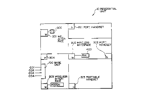
3 o Fig. 1 is a plan view of a resi~len~e having the element~ of the invention
ulcul~oldkd therein;
; . CA 02222416 1997-11-26
Fig. 2 is .~les~ e of a ll)MA frame showing a frame having 8 slots
supporting 4 bidirectional rh~nn,~l.c;
Fig. 3 is a block diagram of a base unit 100 inco,~o,dLing the principles of the present invention;
Fig. 4 is a block diagram of a portable h~nl1cet such as the h~n~cet 200
incorporating the principles of the present invention;
Fig. S is a block ~ gram of a WSLI 300;
Fig. 6 represents a base unit 101 co."~ ihle with ISDN technology which can be
used in lieu of or in combination with the base unit 100 of Fig. 3;
Fig. 7 is a mo(1ifie~l version of the base unit 100 which provides for a t1e~ tr~
digital ch~nn~l to increase the capabilities for f~rcimile and mo~lern applicatiorls;
Fig. 8 is a block rli~grzm of a WSLI arranged to cooperate with the ~eflir~te~l digital
ch~....~l of the base unit of Fig. 7;
Figs. 9A and 9B are a more t1~-t~ile~l block ~ ".." of a suitable
~wi~cl~ rocec~ g unit such as that cn.~ in a WSLI 300 or a h~n-lcet 400;
Fig. 10 is a det~ilP~l block rli~m of a suitable l~ cci~. such as the t.~sce;v~,cont~in~ in the WSLI 300 or the h~ ce~ 400; and
Fig llA is a flow ~~i~m i~ a~ g a typical configuration seqll~nre and Fig. llB
l~lesell~ a r~slllting configuration table resnlting from the configuration sequence.
3 o Detailed Des~ ion of a ~lefe.~d Embc limPrlt
CA 02222416 1997-11-26
Before describing the construction and operation of a ~-efcllcd embodiment of the
invention, ref~lc~lce is made to Fig. 1 to show the marmer in which it may be
employed. More particularly, Fig. 1 is int~n~le~l to ~e~lesellL the floor plan of a
residential unit 10 which inClll(ies several rooms. The reci-lPnt;~l unit 10 hasincorporated therein a ba3e unit 100 and several co~ dLiLIg units inrl~lllin~ portable
h~n-lcetc 301-304 and, in addition, WSLI intPrf~res 201-203. As is rc~lcsc..lcd in
Fig. 1, the base unit 100 is connPctp~i to 4 telephone lines, termed C01
(lc~le3ellling Central Office line 1) through C04. While a base unit 100 interfacing
up to 4 central office lines is illustrated, it will be a~c.ll that by employing the
principles of the invention, more or less than 4 central office lines can be
accommodated. The purpose of the iL vc~ /c apparatus is to provide for
connectivity between one or more of the central office lines C01-CO4 and line-type
telephony devices such as convlontion~1 telephones 300 and a f~s;mile m~rh;nP 400
or a modem 500 or co~cliviLy to one or more portable h~n~1cetC. It is an
important advantage of the present invention that wired co.~nccLions between thecentral office e~ re point (at the base unit 100) and any one of t_e telephones
300, f~rSimile ."~ inP 400 or modem 500, or the telephone h~nf~setc 301-304, is
replaced by the RF media as will be described. For ~ul~oses of this description, we
will assume that the system supports the 7 remotes, which are illustrated.
zo
While Fig. 1 shows the seven remotes at particular locations within the resi~tonre
10, it will be a~ale..l that any remote can be moved at will i..~,....fh as there is no
physical cormection between the CØ ~ re at base unit 100 and the remote. The
only physical rc.luilcLucuL for each remote is a source of power. The power source
could be either a hard wired con.~cc~iou to a 60Hz power source or ~ cly a
battery source. Neither type of power inhibits portability of the remotes.
As will be described in greater detail the remotes come in two varieties. There is a
portable h~ seL idPntifiP~l with lcr~cnce ch~ractPr~s 300 et seq. (described in
comle-;~ion with fig. 4) and the WSLI identified with l~r~ ce ch~r~ctPrs 200 et seq
(described in co.l~le-;lion with fig. 5). The portable h~nrlsPt remote 300 in~ les a
CA 02222416 1997-11-26
microphone and speaker and is typically used for voice services. The WSLI has a
conventional telephony corlnection device (such as an RJ-11) to facilitate
interconnection of any of a conventional telephone, modem, f~csimile m~ in~ or
other wired telephony device. ReC~lce the RF media provides a full bandwidth 300-
3.4 KHz uncolllpl~ssed audio charmel to any remote, the WSLI (in contrast to a
cordless telephone) au~L)OlLa facsimile or modem services.
Fig. 3 is a block diagram of the base unit 100. As seen in Fig. 3, base unit lO0inrll~ s an isolation t~d~,rul,l,er A1 for each of the 4 central office lines CO1-CO4.
Each of the isolation transformers A1 is CO~ Lr~1 in turn to a 2-wire-to-4-wire
hybrid A2. Each of the hybrids A2 is connected in turn to a codec A3. The base
unit 100 also inrln~1es a awiL~;hing/processin~ unit A13. The switching/processingJ
unit A13 incl~ ec 4 ports, one for each of the codecs A3. The switching/procescing
unit A13 interfaces with the Time Division Duplex/Time Division Multiple Access
radio Lld~SCciv~ A15. This int~ re between the swi~_hi~g/procecsing unit Al3
and the l~dll~:iCeiV~,r A15 includes 5 ScpdldLc paths, two pat'ns carry ~ .il data and
clock from the awiLchhlg/procescing unit to the l.rl,l~ceivcr, two additional paths
carry receive data and ~ce;~. clock from the LLdl~cei~L to the
switching/~loeec.s;Qg unit, and a single additional path provides for control of the
ll~scci~eL by the awiL~,hin~/ploce-cciu~ unit. The awil~;hil~g/ploce~ unit A13
also inrlllf7es a user i"l~ r;~re which is imple~"f-llrcl via a collvcllLional
n~i~lu~lucessor~ In order to control the mi ;ru~lucessor and ",~,.;r~a~ comm~n-lc via
the user, a kcybo~l or keypad is employed. The purpose for the user
pro~,~",l-l~bility or configuration control will be rl~srrihe~l below.
The base unit is ucer configurable to allow any coml~i~alion of cormections to be
_ade b~ n the incoming phone lines and the remotes. The intrrf~re l~ hcd for
the user to configure the base unit could take a number of dirrt lell- forms that
include (but are not limited to) co~e~;Lion to a p~ol~al Cu~ uLc~ voice synthesis
3 o and recognition Cil~;uiLl,~, keypad and LCD display, tuuchto~c and LCD display,
voice synthesis and touchtone;
CA 02222416 1997-11-26
Standard 64 Kbps digital encoding is used tO convert the analog phone signals todigital format. Digital signal processing col~ sion of the encoded bit rate is not
n.ocess~ry. Adaptive echo cancellation techniques is used to minimi7e the near-end
echo caused by delay in the digital circuits and phone line miAim~trh The use ofs uncompressed analog-to-digital conversion and the addition of echo cancellation
provides the user with a full bandwidth, distortion-free connection to the phonecompany. This high quality phone channel is ,~ces~,., y for high-speed fax m~rhin.os
and modems and is required to provide the consumer with a "transparent"
connection to the incoming lines.
The network access technique is TDMA/TDD. This term is an abbreviation for
Time Division Multiple Access with Time Division Duplex operation. In a
TDMA/TDD system each unit in the network may obtain a fixed time slot to
transmit and a fixed time slot to receive. In the present embodiment of this
invention, the l~cLwol~ will have a total of eight time slots consisting of four remote-
to-base tr~n.cmi~-sion periods followed by four base-to-remote ~n~mi~ion periods.
These eight slots together colllL,.isc a single frame. Since the system is Time
Division Duplexed (TDD), every remote will have a receive slot for each transmitslot during the frame. The base unit and all of the remote units operate on the same
2 0 frequency ch,-~ rl for both ~ ;L and receive intervals during a frame. Ifintclrcle~ce is e~o~t,.~,d by any of the UIlitS while on this ~h~nn~l, then the base
and all remotes will make a coo~.li~ted frequency change to another ch~l to
avoid the i~tclrclc~ce~. This is referred to as reactive E~ UCA1~Y hopping. The
reactive hopping techniqllP also allows multiple ~y~t~llls to operate when in close
proxirnity to each other by having each system select a clear ch~nntol not in use by
any of the others.
The modulation technique may be any ty-pe of angle or angle/amplitude modulation,
but in a ~lef.,A,ed embodiment is GMSK. Direct sequence or proactive frequency
3 o hopping, spread ~L1ULU techniques may be overlaid on the modulated signal to
broaden the bandwidth and reduce sensitivity to ul~e~r~L~ and multi-path distortion.
- CA 02222416 1997-11-26
Since this product is used in the immP~iAte vicinity of the home, low power
operation of the 4AIICIII;L~ iS anticipated. Lower LlAll~ rf1 power will providefor more re-use of channels in dense neighborhoods that might have a number of
systems.
The functionality of the WSLI and the base unit could be e~ n~lP~ to include
f~rsimile/modem modulation and demodulation. In this exr~n-lP~l embo~liment,
modulated illro. ",Ation coming from a fax ,.,A-~ki.,.~ or modem connPctPd to a WSLI
is demodulated (see Fig. 8) by the WSLI and couv~ d to digital form. These
relatively low speed bits are then encoded with some type of re~ n~lAnt, fol~.d
error correction, coding scheme. The encoded bits are burr~-~d, converted to thestandard slot data rate and trancmittPfl to the base unit. The base unit ~ipmllltirlexes
these bits, reformats them as fax or modem data, and remodulates the bits for
trAnsmicsi~n over the phone line.~5
This process is reversed while ,~ceivillg i~c~ lg fax or modem information. The
base demo~ At~s the fax or modem il ru-~Lion coming in from the outside phone
lines. The reSllltinf~ digital bits are encoded with a fol~v~-l error correction code,
co..v~ d to the ~L~daLd slot data rate and ~ iU~l to the WSLI. The WSLI
rl~rnllltirlexes the bits, re-fo.l. a~ them for fax or mo~lPln data rates and then re-
mo~hll~t~s the bits for ~-A~ ;Oll to the modem or fax.
An additional embo~1imP~t of the iu~ lLion is a version with an ISDN base unit. A
:,l~d~ 2BfD ISDN data frame co~,~L, of two 64 Kbps slots for voice, one 8
Kbps slot for data and one 8 Kbps slot for Ci~A~ , ThcLefo~, one ISDN line can
support two voice circuits and one data circuit. An ISDN-co~ aLible base allows
the user to have access to two voice circuits and one low speed data circuit with
only one i~collling phone line. The 64 Kbps voice slots is also used for data
L~AIICIII;~C~IOT1 if data-rate speeds higher than 8 Kbps are ~ uh~d. No codecs are
3 o needed in the base unit since the illco-.--ll~ and ~uL~oi~ hlful-uaLion is already in
CA 02222416 1997-11-26
digital format. Digital ch~ui~y is used to convert the ISDN data to HPCS format
and back again.
Fig. 4 co~ es a block diagram of a typical h~n-lcet such as the h~nr1~et 300.
The h~n-l~et of Fig. 4 in~ es a codec A3, a ~wi~ g/proc~csing unit A23, its
associated microL,locessol A24 and a radio Lld~SCe;v.,. A25. Although not
illustrated, the h~n-lset 300 may include a dial keypad as in a conventional
"cordless" telephone. ReÇ~.li~ to Pig. 5, the WSLI illustrated includes an isolation
LldllsrolLuer Al coupled to a COL vc"Lional telephony connection point such as the RJ-
0 11 jack. The isolation lld~rolmer Al (which may not be n~cess~, y) in turn is
conn~oct~l to a 2-wire-to 4-wire hybrid A2. The 2-wire-to-4-wire hybrid A2 is
co~ ;tt;cl in turn to a codec A3. The codec A3 is conn~cted in turn to a
switchinglproce~ing unit A23 and the switching/processing unit A23 is conn~cte(l,
in turn, to the TDD/TDMA Lld~SCciv~ A25.
Referring to Figs. 3, 4 and 5, it will be a~a~ L that the base unit 100 in~ os an
isolation tL~Ç~,lLuer Al for each of the C.O. lines, and likewise, the WSLI
inrlll-l.os an isolation Ll~ro,~u~,r which is used to couple the signals from the line
type telephony device (coL~ Lional t~lçphon~o, modem or f~/~cimile ,~ hi"r, etc.).
2o . In like f~hion, the isolation LL~r~.lLuer A1 and the base unit 100 couples these
C.O. lines. The 2-to l wire hybrid A2 Op~aL~S to change the 2-wire format to theleft of the hybrid into the 4-wire format on the right. The 4-wire format in theWS~I as well as in the base unit 100 is then coupled to a codec A3. As shown in
Fig. 4, the hr~ also inrllld~s a codec A4. The codecs A3 and A4 have the
function of couv~.Li~g analog signals l~,ceiv~d from the hybrid (in the case of the
WSLI or base unit) or from the microphone in the case of the h~n~set) to digitalform and, cou~.sely, cou~ , digital signals received from the
switching/~rocess;.~ unit A23 (of the WSLI or h~nti~et or from the
~wiLel~illg/~loce~ g unit A13 of t~e base unit) into analog form and coupling those
3 o analog signals to the 2-to~wire hybrid.
, CA 02222416 1997-11-26
.
13
The switching/proceccing unit A23 receives the digital data from the codec A3 atone rate and, with the a~lo~liaLe timing, provides those signals to the radio
transceiver A25 or A15 at the higher burst rate. Likewise, the switching/processing
unit A23 receives digital data from the radio LL~sceiver A25 or A15 at the burstrate and provides that digital data to the codec, at the a~lo~liate lower rate. The
microprocessor A24 of the h~n~cet also l~ ds to user manipulations to signal
such conditions as on-hook/off-hook and dialing signals.
In general, the switching proceesing unit j?~.rolllls the following:
1) Multiplex and convert the incoming data from the codecs into a serial data
stream that can be handed off to the radio ~ ce;ve~ for tr~ncmicSion~ The rate of
this serial data stream will be slightly faster than eight times the 64 Kbps rate. The
increased data rate arises because of the eight time slot TDMA/TDD format plus
system overhead and ~u~e~visory cll~nnPl bits. The o~.. head and ~u~ visory bits
are expected to add about 10 Kbps to the data stream. The conversion of the slower
codec rates to the higher ~ncmiCcion data rate will be h~n-11e~1 by ~Os and
buffers (see Figs. 9A and 9B).
2) DPmllltirlex and co~.l the 8X serial data stream col,~i~g from the
transceiv~i into the individual 64 Kbps streams for each codec. This process is
b~ir~lly the reverse of the one ~P5rrihefl above.
3) Receiver clock recu~ y. The 8X serial data stream cc~ g from the
2 5 lld~ceiveL is fed into a circuit that extracts a clock signal. This recovered clock is
used to ~y~un~e the ~1~0 circuits and the data buffers used in co.l~ g the de-
multiplexing the l~ceived serial data stream into the individual 64 Kbps codec data
streams. The recovered clock is sent along with the lcce;ved data to the codecs.
3 0 4) Convert the multiplexed, serial data stream into the l~.luil~d b~ebz~
modulation signals that will then be fed to the ~ r. This co~ ion could be
- CA 02222416 1997-11-26
la
as simple as just filtering the data bits or as complicated as creating I and Q
components to be used in a quadrature modulator. In either case, the modulation
signal(s) would be more than just a simple logic level bit strearn.
Conversely, in the base unit 100, the microprocessor A14 provides ring detect
inforrnation from one of the ring ~tet~ctorS RD to in~tir~te that one of the C.O. Iines
has an incoing call. The miclo~lucessol A14 also controls an associated line relay
to in~lic~t~ an off-hook or on-hook condition, as a~p.~.pliate. The m~nner in which
this infol,llaLion is provided to the ~ .opiocessor A14 and the m~nn~-r in which it
0 is used will be described below.
Figs. 9A and 9B show the data and control paths in the switching/processing unitA23. Fig. 9A shows the transmit side of the switching/processing unit A23. As
shown, input data for tr~ncmiccion is input to the shift register SPI. This data is
clocked cQmmc.~ .,.t~ with a 64 Kbps voice çh~nnPl rate. The microcontroller MC
is coupled to an 8-bit latch SPL via a data bus SPD. Thus, if n~cess~ry, the
microcontroller MC can load the latch SPL with cign~ting data for t~ ,.,icsion
The outputs of the shift regi~. SPI and latch SPL are coupled to a data selectorSPS. A control input from the microcontroller MC selects which input source willbe coupled through the data sel~c~ol SPS. The output of the data selector SPS iscoupled to a ~ FIFO SPF. The output of the t~ -llil FIFO SPF is coupled
to an output shift register SPO. The output of the shift ~ . SPO is coupled to
one input of a data selector SPDS. A FIFO input control logic SPCI and output
control logic SPCO are provided to interact with the microcontroller MC, the input
shift register SPI, Il,l-~ FIFO SPF, output shift re~islt;r SPO and output data
selector SPDS.
In operation, when a coJlv~ lion is in progress, data is received at the input shift
register SPI, on a regular basis. I~ is the function of the apparatus of Fig. 9A to
3 o collect that data and output it in burst form via the serial data path output of the
SPDS.
CA 02222416 1997-11-26
Fig. 9B, on the other hand, shows the receive function of the switching/processing
unit A23. As shown in Fig. 9B, receive data (from the ~ ceiver) A25 is input to
the input shift register PSI. The receive data path is also conn,-ct~-~l to the input of
the latch PSL. The output of the latch PSL provides a cign~ling data path to themicrocontroller MC. Data from the input shift register PSI is provided in parallel
form as an input to the receive ~l~O PSF. The receive FIFO PSF provides outputs
to an output shift register PSO and to an 8-bit latch PSLL. The
~wiLclling/procescing unit A23 also inrl l~es input control logic PSCI and output
control logic PSCO which cooperates both with the microcontroller MC, the input
shift register PSI and output shift ~ PSO and the latch PSLL. The output of
the latch PSLL is provided over a data bus to the microcontroller MC. On the other
hand, the serial output of the output shift l~ h~ PSO is provided as an input to the
associated codec A3. Of course, the data rate into codec A3 is commensurate withthe data rate from the codec A3.
Fig. 10 is a block diagram of a suitable radio L.~cei~/er which can be operated in
accolda"ce with the TDD/TD~MA forrnat.
Before describing the op~ tion of a system such as that illustrated in Fig. 1,
,~,f~,-,n~-e is made to Figs. 11A and llB to show a typical configuration session.
The configuration session need only be accomplished once, although the user can
change it at will. The configuration session results in data which is stored in the
mi.~ ocessol A14 of the swi~,hillg/~,ocP~.~;..g unit A13 of the base unit 100.There are a variety of ways in which the user can int~ t with that microprocessor
in order to achieve the .-~cecc~. ~ confi~ A simple int~r~rtion is
accomplished via a ~ 1JO~d. Other int~ tions involve the use of touchtone
telephones or ;~ l;on via a remote intPlligent p,ocess which is then capable of
downloading the a~lo~liat~ data to the Il~ic~o~locessor.
3 o In order to configure the system, it is .-~cess-. ~ for each of the remotes to have an
address. Preferably, the address is ~I~ l,ln, i.e. each remote carries a unique
CA 02222416 1997-11-26
identity or address from the m~mlf~rtllrer. While the product could come with
docnm~nt~tion idc~Liry~ the address for each remote, and the user could input this
address on a keyboard, a simpler process is envisioned. Rec~n~e the base unit 100
inherently can c~ ."""~ t~- with any of the remotes, each remote can be powered
s up in turn to allow the base unit to "learn" the address of that particular remote.
When the base unit has acquired the address of one remote, that remote can be
powered down and the next remote powered up, and so on. In this fashion, the base
unit 100 can acquire a list of the remotes to be configured.
In any event, after il~ ti~ the configuration session, the first function, F1,
requires the user to select a line. Of course, each of the C.O. lines has a directory
nurnber. However, for purposes of configuring the co,~ ,irations system, each
C.O. line may be i~1ent;fi~ by the port at the ~wiL~;hi, g/processing unit A13 to
which it is co~ elr~ T~.c:fo,e, the C.O. line co",l~ct~ to the input "codec 1"
would be line 1, etc. The user, at function F1 for example, selects a line such as
line 1. In step F2, the user specifies (such as via the keyboard or the like) those
remotes in the system which are to ring when the co,~.,*,ollding line is in a ringing
state. When the user inflir~t~s that he has i~lentifi~d all of the remotes which are to
ring for this line, fi-nrtinn F3 is p~, ru....~(l to list the remotes which should be
allowed to access that C.O. line. When the user ,.~.;re~l~ that function F3 is
completed, filnrtion F4 is ~.r~ ed to check wL~LIl~. there are any more lines
which require confi~lr~tion illfol~Lion. If there are, ~l~,cess loops back and
~mrtion~ F1-F3 are ~Lr~ cd for a dirr~.ellL line. Once all lines are configured,the ~lOCcSSiS complete.
Fig. 1 lB shows a table which is created in the microprocessor, storing the datawhich is input by the user. RefelliL~ to Fig. 11B and Fig. 1, the table includes an
in~ tion that when line 1 is in a ringing state, remotes 201, 203 and each of 301-
304 should ring. This allows the-call to be a~ .ed at any of these locations.
Likewise, the table ;,~ s that l~ otes 201, 203 and 301-304 are allowed to
access line 1. The data in the table of Fig. 11B for line 2 is i~ ntir~l to line 1. The
CA 02222416 1997-11-26 _
17
data in the table of Fig. 11B for line 3 shows that only remote 301 will ring inresponse to the ringing state of line 3, and likewise, only remote 301 is allowed to
access line 3. Thus, line 3 is configured as a private line solely for the use of
remote 301. Line 4 is likewise t1~o~ir~tt~fl to remote 202. In the case of remote 2Q2,
however, this remote serves a fax m~rhinl- 400. It should be l~n~ rstood that while
it is important for the base unit to store the configuration table shown in Fig. llB,
there are c-lc~ A~-res in which this information is also useful at each remote.
Accordingly, the table, as part of the configuration session, can be L1AI~ (ed to
each other remote in the system, so that the data is duplicated in each of the
1 o remotes.
The operation of the invention can be explained as follows.
Assume that one of the C.O. lines 1 4 undergoes a francition from an idle condition
to a ringing con~iition~ e.g. for an incoming call. That ringing condition is ~etect~l
by the ring dc~.,~ol RD (see Fig. 3) ~csoci~ed with the C.O. line. The
microprocessor A14 is notified of the ringing line and, after con~llfing with the
table shown in Fig. 11B, inserts a sign~ling message for the remotes associated with
this line. For ~x~mpl~, if the C.O. line in a ring state was associated with a
~e~lir~ted remote, only that remote would receive the sigTl~ling message. When
received, it will stim~ f~ the mic.u~lvcessor A24 to aeLiva~c the ring gcll~ld~or RG
(Fig. 5) which will ring the ~soci~l~~l t~ hn..~ line device, e.g. Co~,.lLional
telephone, modem or f~rcimilP l"~r~i"f~, ~.c.cllming that that ...~ is
"al~."~d", i.e. it goes off-hook, that conrlition will O~F~IC a ci~nAling message to
the rnicfu~locessor A24 which will result in llA.. ~."iccinn of a sign~lin~ message to
the base unit 100. The L~ upfocessor A14 of the base unit 100 will recognize that
the lcc~ivcd sign~ling l.~Fss~gc is associated wifh the previously-l~A~ r~l message
which resulted in Op~dliO~ of the ring gellclalol RG. As a conse~luence, the twosources, i.e. the particular C.O. li~e and the particular remote, will be associated
3 0 with a common C1rAI~F1SO that i~o. .~lion received from the C.O. line will be put
in the slot ~l~Stin~o~1 for the remote, whereas illfollllation ~,,ce;-~cd from the remote
, - CA 02222416 1997-11-26
18
will be retrieved and provided to the C.O. line. In this fashion, a circuit connection
is established. This connection will remain "up" until either the C.O. or the
associated remote goes "on-hook" or idle. The change in state generates a cign~ling
message which is recognized to cease use of the frame. Whereas the previous
scenario po5hl1~fe~1 a call initi~t~rl to the system of Fig. 1, the system of course can
initiate calls d~stin~d for completion over the public switched telephone network.
Such a scenario begins by a user manipulating one of the remotes (either a h~nricet
or a WSLI) so that its state is changed from idle or on-hook to off-hook. The off-
hook transition will gcllcldLc a .cign~ling message to the base unit 100. As is
conventional, a message in~ lcles the source address, i.e. the identity of the remote
initi~ting the message. At the base unit lO0, the table of Fig. llB is consulted to
identify what C.O. lines this particular remote is entitled to access. The base unit
100 also has "visibility" of the condition of the C.O. lines, i.e. in use or idle.
Assuming there is a match between a C.O. line which the remote is entitled to
access and an idle C.O. line, the base unit initiate an on-hook to off-hook transition
for that C.O. line. This will initiate receipt of a dial tone at the associated codec.
Receipt of the dial tone is t~ ullL to receiving voice information, and the baseunit acts accold-,-gly, i.e. the information is tligiti7~d and tr~n.~mitte~l in an
a~ro~ slot to the remote which ;..;~ d the seqllen~e. As a consequence of the
foregoing, the user having forced the remote to an off-hook state, will "hear" the
dial tone whose source is at the C.O. line which has been enabled by the off-hook
message to the base unit. At this point, the user can Ndial" the desirçd connection.
Dialed digits can be treated either as si~n~lin~ data or as audio and, in any event~
the result is repeaLi~ the dialed digits by the base unit to the a~lo~liate C.O. line.
2s The user, rather than dialing an outside call would well have dialed the identity of
another remote. The base unit has sufficient intelligence to dirr~ lLiate a calldestin~ for the public switched telephone n~wolk from a call ~ci n~ting a remote.
The base unit 100, in addition to clet~cting the addl~ i~ of a remote, also has
h~follllaLion rPspecting the on-hook-or off-hook status of that remote. Thus the base
3 o unit can, if a remote is addressed and is on-hook, cause a ringing m~Ss~ge to be
CA 02222416 1997-11-26
19
tr~ncmitt~l to that remote in order to complete the connection between the calling
and called remote.
In general, a frame with 8 slots corresponds to 4 ~h~nn~lc, which allows 4
Siml-lt~nt'OUSly, SepdldL~: circuits. Each circuit can include one of the CØ lines and
one of the remotes. ~It~ ;-t;v~ly, a circuit can include 2 remotes, in the absence of
a C.O. line.
If desired, 2 "circuits" can be associated in a single coll~,c.~ation so that, for
example, 2 remotes and a C.O. line can be coLLfel~.~ed together. A "circuit",
which is ~ .f ce~ to support a conversation, requires a path, for example at each
remote for talking and li~t~?ning. The talking path is used to carry the voice from
the remote to the base, whereas the li~te-lin~ path is used to carry voice traffic from
the base to the remote. If a co~ Lion is to include three sources, say remote A
and remote B as well as a C.O. line, each of the remotes has a t~ t-~ transmit -slot to carry voice traffic from that remote to the base unit. At the base unit, the
data from remotes A and B are combined to provide the voice traffic to the C.O.
line. The listen slot for remote A will include a con~te~-~tion of voice traffic from
the C.O. Iine and voice traffic from remote B, and the listen slot for remote B will
likewise be a co.~r~tf ~ ;o~ or s~,.. ;.. g of voice traffic from the C.O. line and
voice traffic from the remote A.
Fig. 6 shows an ~ --,l;ve base unit to the base unit 100 of Fig. 3. The base unit
of Fig. 6 is ISDN cn...p~;hle. An ISDN "port" carries 2B + D, that is 2 bearer
l h~nnf-l~ l data ch~nn~l Accordingly, each ISDN line is coupled to a ~omnltirlexer
DM. The flemllltirlexer provides 2 voice line (noted as voice 1 and voice 2 in Fig.
6) and a data line, input to a ~wiL~ g/~ ces~ unit A30. The second ISDN line
shown in Fig. 6 is also coupled to a similar ~lemllltirlexer DM which provides 2additional voice paths and an addi~ional data path to the ~wiL~;hing/proces~ing unit
3 o A30. Thus, the ~wit~hillg/proce~sing unit A30 has 4 voice paths (voice 1 - voice 4)
CA 02222416 1997-11-26
and 2 data paths (data 1 and data 2). The switching/processing unit A30 is in turn
coupled to a TDD/TDMA radio Ll~lsceiver A35.
-
The ISDN-c~mr~tible base unit shown in Fig. 6 can be substituted in lieu of the
base unit 100 of Fig. 3 for cooperation with ISD~ telephony lines in lieu of theconventional telephone line associated with the base unit 100 of Fig. 3. Since the
ISDN lines are ~ ti7e~l~ no codecs are nredpf~
Figs. 7 and 8 show a variant in which the filnrtion~lity of the WSLI and the base
unit 100 are e~p~n-le~l to include f~rsimile/modem modulation and demodulation.
Referring to Figs. 7 and 8, Fig. 7 shows a modified base unit, one which differsfrom the base unit of Fig. 3 in that rather than having a hybrid such as the hybrid
A2, the base unit shown in Fig. 7 with respect to the lowest-most C.O. line, has a
fzlrsimile and modem modnl~tQr/demodulator A38. In ~ rion, rather than having
the codec A3 as is associated with the other C.O. Iines for the base unit of Fig. 7,
the fax and modem mo~ tor/demodulator A38 is coupled to the
switching/processing unit A13 via a fo-w~.l-acting error correction encoder/decoder
A40. The co~Li~g WSLI remote (see Fig. 8) has a collc~onding fax and
modem modulator/demodulator A43 and a coll~onding ful ward-acting error
2 0 correction encoder/decoder A42. More particularly, the WSLI of Fig. 8 receives
for example f~rcimil~ mo~ t~rl i~o~ on on its input via the isolation
lld~,fu~ cr A1. The f~rcimile and modem mo~ trlrldpmo~ tor A43
demodulates the i~lÇ~ on 1~ ce;vcd from the f~r5imilç ~ rhinP and provides
digital data cull~onding to the output of the ~Ccoci~t~d f~csimile m~rhin-- to the
fonvard-acting error col.c~iLion encoder A42. The Pnro~1ed bits are then burr~lcd
and converted to a ~L;~dal-l data rate for the co-"-,~ ;onc system and trzmcmitt~l
to the base unit (of Fig. 7). In the base unit, the Çol~v~d acting error col~ ed data
is coupled to the folwa. l acting error correcting encoder/decoder A40 where therU~ ld acting error coll.,~,lion is stripped out, and the data collvelLed to its raw
3 o digital form. The data in the raw digital form is then provided to the facsimile and
modem modulator/demodulator A38 where the digital data is again mo~ ted and
CA 02222416 1997-11-26
21
coupled via the isolation transformer Al so as to appear in the form in which the
isolation Lldl~Ç~ er Al (of the WSI~) had received the data initially. The
demodulation (at A43), forward action error correction (at A42) and the
corresponding operation of A40 and A38 increases the robustness of the
co~ ;cdLion Cll~l"~ . Another variant on the WSI,I can employ a similar
principle to that which has just been tl~-srribed Those skilled in the art are f~mi1i~r
with the fact that a co~ euLional modem takes digital iur~ lation and modulates that
illfolll-a~ion onto a carrier for ~ ic~ion over the telephone nelwolk. As has been
described herein, a user can co~le~;L a modem to a WSLI which will receive the
modulated illrullll~tion from the modem and act as an extension of the telephonenetwork so that the modulated information can be L~ via the RF media to
the base unit from where it is Lldl~r~ d into the wired telephone network.
However, in~sm11rh as the RF media described herein is a digital me~ m, the
modem employed by the user for the Ll,,.1c...ic.~ijon of digital i~ollllation could well
be located in the base unit and not ext~ 1 to a WSLI. More particularly, a WSLI
may include an RS-232 port which will accept digital infol~lation from a computer
or the like. The RS-232-type WSLI then accepts the digital information and
tr~ncmitc it over the digital RF media to a base unit such as the base unit lO0 of
Fig. 3. This base unit, however, is modified so as to employ a modem in lieu of
2 o the codec A3. The output of the modem is then applied to the 2-wire-to~wire
hybrid A2 as if it were a codec A3. While such an RS-232-equipped WSLI and
base unit could also ~iu~olL voice services via an RJ-ll port, it is withiTl the spirit
of the invention to employ a WSLI which ~u~polL~ only RS-232 services.
Those skilled in the art are readily f~mi1i~r with TDMA L,~scei~/e.~ supporting a
multiple access frame such as the frame illustrated in Fig. 2. The Time DivisionDuplex variant on TDMA provides, in a pair of slots, a bidirectional ch~nn~l. For
example, slots l and 5 provide a bidirectional rh~nn.-1 bcLwccll the base and a
remote, slots 2 and 6 are a simi1ar ch~nnPI to another remote, etc. Referring for
3 o example to Fig. 2, if we postulate a "circuit" involving COl and a remote 303 and
further assume that the "call" is initi~trd from the C.O. line, and at the time the call
CA 02222416 1997-11-26
is received at the base unit lO0, there is no other traffic in the system shown in Fig.
1. When the base unit lO0 recognizes the illCOl~ g call, it will, after consulting the
table of Fig. 1 lB identify, for example, that the call is destined for the remote 303.
A si~n~lin~ message will then be inserted into the slot "base-to-remote A" of Fig. 2,
addressed to the remote 303. ~csl-ming that the remote 303 is, at the time, not
busy, that is, it is idle, the result of the sign~lin~ message, when received at the
remote 303, will be a ring condition at the remote. ~csllming further that there is a
person to answer the call, then the remote will gO from the on-hook to off-hook
state. This will g~l~LdL~ a cign~ling message back to the base unit. This signaling
message wiIl be inserted in the nremote A-to-basen slot of the frame (see Fig. 2).
Receipt of this message will inf~ te to the base unit that the remote 303 has
al~w~l~,d the call, and a "connection" will be made. This connection is really an
en-try into a memory location which in-lic~t~s that voice traffic from CO1 will be
inserted in the slot of the frame "base-to-remote An. Likewise, at the remote 303,
the switching/pr~cecsin~ unit will ensure that voice traffic from the remote is placed
in the slot nremote A-to-base". The swiLhing/~locPs~ unit of the remote 303
will extract voice traffic from the slot nbase-to-remote A", and convert that voice
traffic to ~n~log form. The base unit, col.~ ely, will extract voice traffic from the
slot "remote A-to-base", convert that voice traffic to ~nalog form, and provide it to
CO1. This state of affairs will remain until one or the other of the CO1 and remote
303 goes on-hook. That change of state will result in tearing down the "circuit"?
i.e. el;...;n~ the data which had previously di.~cl~d the e~rh~ e of signals
b..we~ the remote 303 and CO1.
2 5 While the foregoing has desclibed specific e~ les COlll~liSillg a prere~led
embodiment of the invention inrhl~1ing several ~ ;ves, those skilled in the art,after having reviewed the application, will readily lln~Pr.ct~n~1 still other alL~l~,atives,
also falling within the spirit and scope of the invention. While the application has
specifically t1icc~sse~ wire-type telephony devices in~ in~ telPFh~ ~Ps, f~rcimile
3o m~hin-os and mo~ipn~c~ other wire-type telepholly devices may also employ the
services of the invention. While a particular radio plotocol employing 4
CA 02222416 1997-11-26
. .
bidirection~ h~nn.olc has been illustrated, çh~nging the number of channels
employed is also within the spirit and scope of the present invention. Accordingly,
the scope of the invention is to be conctrued, not by the specific examples described
herein, but by the claims appended hereto.