Note: Descriptions are shown in the official language in which they were submitted.
CA 02222442 1997-11-26
WO 96/40410 PCT/US96/08908
MICROWAVE A88I8TED CLEANING 11ND RECLAMATION
OF INDO8TRIl~L WA8TE8
The present invention relates generally to
treatment of industrial wastes, and more particularly
to microwave assisted cleaning and reclamation of
oily metallic industrial wastes.
BACKGROUND OF THE INVENTION
Several industrial processes produce oily
mixed wastes.. One example is hot strip rolling steel
mills. Cooling water from these mills generally
contains oily metallic particles. Typical treatment
processes for these wastes use tanks and chemicals
for flocculating, settling, thickening, de-watering,
and stiffening to produce concentrated waste sludge.
Figure 1 shows a block diagram of a typical
treatment plant for processing oily cooling water
from a hot strip rolling mill. The waste effluent
enters a rapid mix tank 20, as shown by arrow 22,
where it is mixed with an anionic polymer. From
there, it proceeds through conduits 24 to clarifying
tanks 26, as shown by arrows 25, where oil is skimmed
off, as shown by arrows 28, and water is removed, as
shown by arrows 30, and directed to a wet well 32.
From the wet well 32, the water is directed through
pressure filters 34, a cooling tower 36, and into a
cold well 38, as shown by arrows 33,35 and 37, to
provide a source of cooling water for the mill again.
CA 02222442 1997-11-26
WO 96/40410 PCT/US96/08908
-2-
The remaining waste 39 from the clarifying tanks 26
is directed through conduits 40 to thickening tank
42, as shown by arrows 41, where anionic and/or
cationic polymers, and/or sulfuric acid are added.
The thickened waste 44 is then directed through
conduit 46 to drum filter 48, as shown by arrow 47,
and finally deposited as a waste sludge cake in
receptacle 50, as shown by arrow 49.
The sludge volume is typically approximately
1/3 water, 1/3 oil, and 1/3 iron metal and iron
oxides, to which lime is added for stiffening. The
waste sludge is typically disposed of in a special
landfill or trucked to a special processing plant
external to the producing company.
A typical hot strip rolling mill can generate
50 tons of sludge per day and more than 7,000 tons
per year. The costs associated with production and
disposal of this sludge are significant.
Moreover, conventional water treatment
processes are time consuming, and plant equipment is
very bulky, requiring extensive housing space at mill
facilities. Also, as land fills reach capacity, the
cost of disposal of mill waste sludge can be expected
to increase.
Accordingly, there is a need for faster,
smaller and more economical industrial waste water
treatment systems.
There are many known processes for the
separation of oil and water emulsions. These
processes are commonly referred to as emulsion
cracking. Emulsion cracking typically needs the
addition of heat and frequently requires de-
emulsifying chemical agents. Processing times using
gravity settling methods often require 4~to 24 hours
for better than 90% separation.
Recently, oil/water emulsion cracking systems
using microwave energy have been successfully field
CA 02222442 1997-11-26
WO 96/40410 PCT/US96/08908
-3-
tested and are currently being developed, mainly for
the petroleum industry. Microwave emulsion cracking
systems are compact and have demonstrated rapid,
continuous, processing at flow rates to beyond 50
gallons-per-minute (gpm), through the use of flow
through microwave applicators. Efficient microwave
processing typically requires only a 20°C process
temperature rise and uses power, for example, at an 8
to 12 kilowatts per gallon per minute (kW/gpm) power-
to processing rate. For some applications, microwave
emulsion cracking has the added benefit of not
requiring the addition of chemicals.
While these methods may improve the
separation of oil-water emulsions, they do not
address the distinct problem of additionally
separating oil from metallic solids frequently
present in industrial waste effluents, such as
cooling water from hot strip rolling mills.
Accordingly, it is an object of the present
2o invention to provide a method for treating industrial
wastes containing oily metallic solids by separating
a waste into its various components for reclamation
and reuse, thereby significantly reducing or
eliminating waste sludge.
It is also an object of the present invention
to provide waste water treatment process equipment
that is faster and more compact than that presently
typically used.
Additional objects and advantages of the
invention will be set forth in the description which
follows, and in part will be obvious from the
description, or may be learned by practice of the
invention. The objects and advantages of the
invention may be realized and obtained by means of
the instrumentalities and combinations particularly
pointed out in the claims.
CA 02222442 2005-06-29
. 77471-30
-4-
SUMMARY OF THE INVENTION
The present invention provides a process and
apparatus for cleaning and reclamation of an industrial
waste containing oily metallic solids by magnetically
concentrating the oily magnetic solids, mixing the
concentrated solids with a chemical release agent, applying
microwave radiation to the mixture, and separately
collecting the clean metallic solids and recovered oil
components.
In accordance with an aspect of the present
invention, there is provided a process for cleaning and
reclamation of an industrial waste containing oily metallic
solids, comprising: magnetically concentrating the oily
metallic solids in said waste; mixing said concentrated
solids with a chemical release agent; applying microwave
radiation to said mixture; and separately collecting the
recovered oil and metal components of said mixture.
In accordance with another aspect of the present
invention, there is provided an apparatus for cleaning and
reclamation of an industrial waste containing oily metallic
solids, comprising: a magnetic concentrator for collecting
the magnetic solids in said waste; a receptacle connected to
said magnetic concentrator by a first conduit for receiving
said magnetically concentrated solids and mixing said solids
with a chemical release agent; a microwave process chamber
connected to said receptacle by a second conduit for
applying microwave radiation to the magnetic solids and
chemical release agent mixture; and a separation device for
collecting clean metallic solids connected to said microwave
process chamber by a third conduit.
CA 02222442 2005-06-29
77471-30
-4a-
BRIEF DESCRIPTION OF THE DRAWINGS
The accompanying drawings, which are incorporated
in and constitute a part of the specification, schematically
illustrate a preferred embodiment of the invention and,
together with the general description given above and the
detailed description of the preferred embodiment given
below, serve to explain the principles of the invention.
Figure 1 is a schematic diagram of a typical prior
art waste water treatment plant.
Figure 2A is a graph showing the results the
experimental treatment of magnetically concentrated oily
metallic waste with oil release agent and conventional
heating.
Figure 2B is a graph showing the results the
experimental treatment of magnetically concentrated oily
metallic waste with oil release agent and microwave
radiation.
Figure 3 is a schematic diagram of a waste water
treatment plant in accordance with a preferred embodiment of
the present invention.
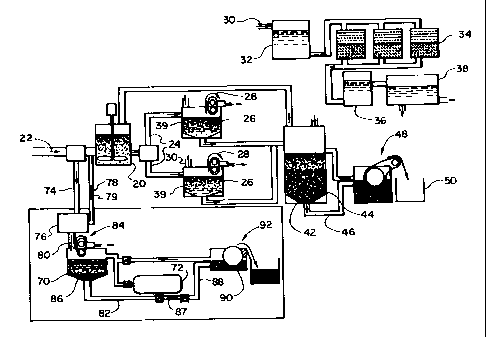
DETAILED DESCRIPTION OF THE INVENTION
The present invention is described below in terms
of a preferred embodiment, that of a microwave process
system that is retrofitted alongside an
CA 02222442 1997-11-26
WO 96/40410 PCT/US96/08908
-5-
exiting waste water processing system. The process
system may also be installed as an alternative to a
conventional waste water processing system.
There are two main steps in the microwave
waste recovery process. The first step magnetically
concentrates the oily metallic particle solids from
the industrial waste effluent. The second step
separates the oil from the metallic solids using
microwave processing. Figure 3 shows a microwave
waste recovery process system installed in a typical
water treatment plant for hot strip rolling mill
effluent. A system uses state-of-the-art, fully
automatic batch processing. Hatch processing may use
a clarifies 70 which is filled and then separated in
repeating cycles. Continuous processing can be
enhanced by adding a second batch clarifies following
the microwave process chamber 72 (not shown).
Further, the microwave process chamber may be
followed by a centrifuge to continuously separate the
solids from the process fluid. The centrifuge may
also be followed by an oil-water coalesces or liquid-
liquid centrifuge to continuously separate the oil
from the chemical release agent. The system may also
incorporate bulk storage tanks containing the
chemical release agent to be used for slurrying the
sludges.
Referring to Figure 3, the first step in the
microwave waste recovery process is to divert the
mill's cooling water process stream through conduit
74 to an industrial size magnetic concentrator 76, as
shown by arrow 75. The oily metallic solids in this
stream are then magnetically separated and
concentrated. Concentration is performed to reduce
the microwave process-flow-rates, tank sizes, and
system volume. The water stream, now stripped of
oily metallic solids, is returned to the rapid mix
tank 20 of the conventional system through conduit
CA 02222442 1997-11-26
WO 96/40410 PCT/US96/08908
-6-
78, as shown by arrow 79. Alternatively, where the
microwave process system replaces a conventional
waste water process system, water from the
clarification step may be diverted from arrow 79, as
shown by arrows 30, to a wet well 32. From the wet
well 32, the water may be directed through pressure
filters 34, a cooling tower 36, and into a cold well
38 to provide a source of cooling water for the mill
again.
Magnetic concentration systems for use with
steel manufacturing waste water effluent have
previously been successfully demonstrated by pilot
systems in the Unites States, Sweden, and Japan.
These magnetic concentration systems are referred to
as High Gradient Magnetic Separation (HGMS) devices.
Commercial, full production scale, units have been
installed and successfully utilized in Japan to
remove suspended oily metallic solids in hot strip
rolling mill waste water, continuous casting waste
water, and other related applications.
HGMS systems are practical, compact, and
efficient. These systems typically require less than
one-tenth the plant floor area of older clarifier and
settling tank equipment hardware. Magnetic
filtration efficiencies of over 90% are achieved with
filtrate effluent average suspended solids
concentrations of l0 parts-per-million (ppm) or less.
Power usage is about 9 kilowatts (kW) per 1000 gpm of
waste water process rate. Power usage may be reduced
through the use of permanent magnet technology such
as Wet High Intensity Magnetic Separation (WHIMS)
technology and others.
Extremely high-flow-rate magnetic
concentrators are also commercially available. Flow
rates of 18,000 gpm have been achieved for magnetic
separation processes in applications for steel mill
waste and process waters.
CA 02222442 1997-11-26
WO 96/40410 PCT/US96/08908
_7-
The concentrated oily metallic solid output
from the magnetic concentrator 76, shown by arrow 80,
is mixed with a chemical release agent in the
clarifier 70 or other mixing receptacle. The
chemical release agent may be nearly any surfactant
and/or solvent with oil release properties. For
instance, saponified aqueous systems or semi-aqueous
systems may be used. Ideally, the chemical release
agent should combine good metal-oil release
l0 properties with good agent-oil release properties,
that is, good cleaning and good oil-rejection
properties. A preferred chemical release agent is
TRIM~ RINSE 200, an oil release agent available from
the Master Chemical Corporation, Perrysburg, Ohio.
TRIM~ RINSE 200 has the following composition: 10-
20% sodium silicate, 1-10% amine carboxylate, 1-10%
sodium borate, 1-10% of an anionic surfactant, 1-10%
of sodium benzoate, 1-10% of a nonionic surfactant,
and less than 1% dye, the balance being water. The
agent is certified on its Manufacturer's Safety Data
Sheet (MSDS) as nontoxic, and noncombustible. Other
chemical release agents having similar oil-cleaning
and/or releasing properties may also be used.
Moreover, release agents without the oil rejection
property of the preferred agents may be used in the
practice of the present invention. These latter
agents may be reused in the closed loop system until
spent, that is, substantially saturated with oil,
after which they may be removed from the system for
disposal or further processing to recover the oil.
An amount of release agent sufficient to
release substantially all of the oil from the
metallic solids in the slurry should be used.
Generally, the release agent is obtained in a
concentrated form which may first be diluted in water
to a final concentration of about 500 parts-per-
million (ppm) to 100%. A preferred concentration
CA 02222442 1997-11-26
WO 96/40410 PCT/US96/08908
-8-
range is about 1 to 15%. The diluted release agent,
sometimes referred to as a process fluid, is then
mixed with the slurry to be treated in a ratio from
about 1/4:1 to 10:1, preferably 1:1 to 4:1. A
typical example is a 5% concentration of release
agent mixed 1:1 with the oily metallic waste slurry
to be treated.
The mixture is then directed through conduit
82, as shown by arrow 81, to a flow-through microwave
process chamber 72. All microwave hardware
components are readily scaled and commercially
available. An example is a 15 gpm process chamber
suitable for full production scale processing. Based
on the 12 kW/gpm power-processing rate, an 180 kW
microwave power source is required. Three 60 kW (180
kW total) microwave power sources are available, for
instance, from Micro-Dry, Inc., Kentucky, U.S.A. Any
application of microwave radiation sufficient to
enhance separation of oil from metal particulates may
be used. Preferred microwave applications are in the
range of about 1-100 kW/gpm. Particularly preferred
applications are in the range of about 10-20 kW/gpm.
Exposure to microwave energy rapidly cleans
the oil from the metallic particles and promotes the
separation of the oil from the mixture. The
microwave processed slurry is then returned to the
clarifies 70 or other receptacle, as shown by arrow
83, or directed to a second clarifies or other
receptacle (not shown) and held to allow the metallic
component 86 to settle. During settling in the
clarifies 70, the oil rises to the top and is removed
using skimmers 84, as shown by arrow 85, an efficient
and low cost method.
The substantially oil free mixture containing
the settled metallic component 86 and chemical
release agent is then directed through conduits 82
and 88, as shown by arrow 87, to separation chamber
CA 02222442 1997-11-26
WO 96/40410 PCT/US96/08908
_g-
90 where the metallic component 86 is magnetically or
otherwise separated from the mixture, as shown by
arrow 91, using commercially available hardware 92,
such as a drum filter.
The microwave process chamber may also be
followed by a centrifuge or other means to separate,
to continuously separate the solids from the process
fluid. Further, the centrifuge may be followed by an
oil-water coalesces, liquid-liquid centrifuge, or
other means to continuously separate the oil from the
oil release agent/microwave-process fluid. The
solids may be further processed by single or multiple
additional rinse stages) for enhanced cleaning.
Also, a system for the recovery of the residual or
spent oil release agent/microwave process fluid can
be installed. Similarly, water purification or
recovery systems can be installed to assist reuse of
the process fluid, which may contain water, or to
meet local discharge requirements. Three-phase
centrifuges, which can combine some of these
operations, also are available.
Following separation of the oil and metallic
components of the original slurry, the chemical
release agent is then returned to the clarifies 70 or
other receptacle through conduit 94, as shown by
arrow 89, in order to be reused.
Independent testing of the preferred chemical
release agent, TRIM~ RINSE 200, is certified on its
Manufacturer's Safety Data Sheet (MSDS) to be
nontoxic, and noncombustible. This certification
indicates that there should be no disposal problems
due to residual carry-off in the oil and metal
products. Furthermore, such chemical release agents
are reusable for a long period of time. The
microwave process chemical release agent is confined
to a closed--loop system, as described above, for its
continual reuse.
CA 02222442 1997-11-26
WO 96/40410 PCT/US96/08908
-10-
The microwave-processed waste is transformed
into individually reclaimed, recyclable components.
The reclaimed clean oil can be sent to reprocessing
sites readily accessible across the country.
Similarly, the reclaimed clean metal can be sintered
or otherwise recycled.
Exam a
The method of the present invention was
developed and tested in laboratory-scale experiments
l0 using hot strip rolling mill waste water samples. A
600 watt White Westinghouse consumer grade microwave
oven was used to microwave process test samples
contained in beakers. A precision, 0 to 500 watt,
industrial 2.5 gigahertz (GHz) microwave power
source, Model 420B manufactured by Micro-Now Co., was
used to supply power into a flow-through waveguide
process chamber. Two design versions of flow-through
microwave process chambers, where one utilized an
oven cavity and the other a microwave flow-through
wave guide applicator were used. Both allowed flow
rates up to approximately 1 gallon-per-minute (gpm).
All microwave power sources which were used
for the laboratory scale testing delivered about 500
watts at full setting. The 500 watts of available
microwave power, in practice, limited the usable
processing flow rates to about 0.05 gpm. However,
off-the-shelf microwave power sources are available
to beyond 60 kilowatts.
Initially, a Nalco~ de-emulsifier was used to
evaluate hot strip rolling mill waste sludge samples.
Typical thickened waste sludge would not separate
with the Nalco~ de-emulsifier either by conventional
heating or microwave heating of 500 milliliter
samples in beakers. Simple decanting and 24 hour
evaporation of the sludge suggested that the water
was not tightly bound in an emulsion. After further
CA 02222442 1997-11-26
WO 96/40410 PCT/US96/08908
-lI-
evaluation, it was concluded that thickened sludge is
not an emulsion, but a water slurry with oil,
polymers and metallic solids.
Qualitative tests were performed with
tetrafluoroethylene (TFE) solvent and a simple
detergent at ambient and elevated temperatures to
evaluate extraction of the oil from the sludge.
Three TFE extractions removed nearly all of the oil.
The detergent, at ambient and 60°C elevated
temperatures, had a small extraction effect.
Microwave exposure of the thickened sludge with the
detergent also had a similar but small effect.
A different methodology, that of the present
invention, described below, was developed to separate
the oil from the waste metal solids. A batch of
magnetically concentrated oily metallic solids was
prepared from industrial samples. The samples of
magnetically concentrated hot strip rolling mill oily
metallic waste solids were prepared by hand using a
plastic coated bar magnet. The magnet had a one
piece integral 18" handle and is typically used to
retrieve stirring magnets. The magnet was slowly and
continuously circulated in 5-gallon sample buckets of
hot strip mill coolant water from a water treatment
plant's main influent, as shown by arrow 22 in Figure
1. The magnetically concentrated oily metallic
solids were stripped from the magnet by hand and then
placed into a calibrated syringe for measured
injection into process vials.
Note that for large scale processes, motor
driven magnetic roll (or drum).separators are
available to extract fine metallic solids from
coolant water. The systems are typically used in the
machining industry and can handle coolant water flow
rates to 300 gpm as a catalog listed item. Eriez
Magnetics, Inc. or Magnetool, Inc. is a source for an
automated concentrator. Extremely high flow rate
CA 02222442 1997-11-26
PCT/US96/08908
WO 96/40410
-12-
magnetic concentrators are also commercially
available. Flow rates of 18,000 gpm being processed
by magnetic separation in applications for steel mill
waste and process waters have been cited.
Two 5 ml samples of magnetically concentrated
hot strip rolling mill oily metallic waste solids
were prepared and processed. A comparison of
conventional heating and microwave processing was
made using TRIM~ RINSE 200 from the Master Chemical
Corporation, Perrysburg, Ohio. Each sample was
combined with the release agent, sealed in a process
vial and heated according to the following protocol:
Two samples, A and B, were mixed with the oil release
agent. Sample A was then placed in a 60°C water bath
for 24 hours. Sample B was exposed to microwave
radiation for 15 seconds, and then placed in a 60°C
water bath for 24 hours.
The separation and settling of magnetically
concentrated oily metallic waste samples are plotted
in Figures 2A and 2H as functions of time. Figure 2A
represents the conventionally heated Sample A.
Figure 2B represents the microwave processed Sample
B.
A comparison of the graphs shows that after
10 minutes, the microwave treatment had twice the
separation or settling of metallic solids. The
microwave processed sample (B) showed no significant
change in the metallic solids settling after 30
minutes. The settled metal solids were about 25%,
+/- 5%, by volume. The conventionally heated sample
(A) required 24 hours to achieve the same 25% settled
metal solids result. Also note that the
conventionally heated sample (A) was still clearing a
mixed phase after 24 hours.
In summary, the microwave processed sample
(B) substantially completed the separation of the oil
from the metal solids in 30 minutes or less as
CA 02222442 1997-11-26
WO 96/40410 PCT/US96/08908
-13-
compared to 24 hours for the conventionally heated
sample (A). This is a factor of 48 times improvement
(98% reduction) in separation time through the use of
microwaves compared to conventional heating.
The microwave method for the separation of
oily metallic solids of the present invention is
useful in commercial processes. The processing can
be implemented using commercially available magnetic
concentration equipment and microwave hardware
components. The microwave process equipment is
extremely compact. The process hardware is capable
of replacing the bulk of existing water treatment
plant equipment in about one-tenth the area. The
microwave process equipment may replace existing
equipment, or may be retrofitted and there is no need
to remove or shut down the existing cooling water
treatment process equipment. The invention achieves
a substantial cost savings to a hot strip mill
operation, with the benefits of recycling and near
zero waste production.
In summary, a process and apparatus for
cleaning and reclamation of an industrial waste
containing oily metallic solids has been described.
The present invention has been described in
terms of a preferred embodiment. The invention,
however, is not limited to the embodiment depicted
and described. Rather, the scope of the invention is
deffined by the appended claims.