Note: Descriptions are shown in the official language in which they were submitted.
CA 02222474 1997-11-26
WAD 96/39789 PCT/US96/07338
INDUCTION WELDING OF TUBING WITH MULTIPLE INDUCTION COILS
Field of the Invention
TYai_s invention relates to the welding together of
facing edge portions of a pair of metal strips, of a single
metal strip or sheet which is folded into a tube as the tube
and sheet are advanced or of a metal strip to a tube using
induction coils far causing high frequency electrical
heating current, e.g. 100 kHz or higher, to flow at the edge
f aces .
~ckgraund of the Invention
Thsa welding together of facing edge portions of metal
strips or sheets using an induction coil supplied with high
frequency current, e.g. at 10 kHz and up to 450 kHz, for
taking advantage of skin effect, to induce current in the
strips or sheets which flows in opposite directions at the
faces of: the edge portions, for taking advantage of
"proxiau_ty effect", is well known in the art. See, for
example,. U.S. Patents Nos. 2,763,756: 3,037,105: 4,197,441
and 4,845,326. The practice has been to use a single
induction coil in various relations to the parts to be
welded together. For example, in the welding of strip
folded around an axis to form a tube, the induction coil has
encircl.s:d the axis either outside or inside the tube. Since
the induced current must flow in a closed path, the current
flowing along the edge faces which are being brought
together- is useful, but since the current must also flow
along tYie inner or outer peripheral surfaces of the tube to
complete: the path, heating, which is not useful, also occurs
at such surfaces .
In an attempt to reduce such non-useful losses,
induction coils which are located at only one side of the
surface~~ of the metal part or parts, sometimes known as a
"pancak:e" or "split induction" coils have been developed.
However,. with such coils, it is difficult to obtain the
desired coupling between the parts and the coils and in
addition, the impedance of such coils is relatively high
which causes current load matching problems and difficulty
in providing sufficient power to a coil for producing rapid
heating of the edge faces.
CA 02222474 1997-11-26
WO 96/39789 PCT/US96/07338
-2-
The latter problems have assumed more importance
because vacuum tube power sources, which can feed loads of
high impedance, are being replaced by solid state power
sources which require a relatively low impedance load. ,
There are difficulties and additional expense in adding
a. second induction coil to a system using a single induction .
coil. Aside from the additional cost of adding a second
induction coil, there is the problem of providing
connections to the second coil, which must permit the parts
to be fed between two coils and when one coil is to be
within a tube, there are support problems, current supply
and size change problems. Even if those skilled in the art
may have considered the addition of a second induction coil,
which is not admitted, they would have believed that each
coil would be required to supply part of the power required
when a single coil is involved and that the problems
encountered when a second coil is used would not be worth
the effort.
Surprisingly, I have found that even though there are
the mechanical problems, such as support, current supply and
size change, the electrical efficiency or economy in energy
use, when two coils are used, are so great that the
mechanical problems can be tolerated. Furthermore, the use
of two induction coils can substantially reduce the load
impedance so that the two induction coils can be fed by
power sources requiring low impedance loads, such as a solid
state power source.
Thus, I have found that the efficiency of induction
welding can be substantially increased with a pair of
induction coils disposed as described hereinafter.
Tests which have been conducted have provided the
following results:
System Power Efficiencv ,
Contact current supply 22 Kw 100$
Outside coil around tube
as in Pat. No. 3,037,105 48 Kw 46~
Inside coil around tube axis 50 Kw 44~
Both foregoing coils
parallel fed 33 Kw 66~
CA 02222474 1997-11-26
WO 96/39789 PCT/US96/07338
-3- '
Split induction coil outside
tube as in Fig. 32 of Pat. No.
4,1.97,441 44.5 Kw 49~
Split induction coil inside
tube under "V" 36 Kw 61~
Both split induction coils
parallel fed 29 Kw 76~
'The testa were conducted in connection with a stationary
'twelve inch diameter steel pipe having a wall thickness of
~one-quarter inch and a power source supplying electrical
energy a:t a frequency of about 200 kHz. The edge faces of
'the folded metal strip were brought together at a weld point
and were: spaced apart for six inches in advance of the weld
point to provide a "V" in advance of the weld point. The
contact current supply system, which was similar to the
system shown in U.S. Patent No. 2,818,489, was assumed, for
comparison purposes, to have an efficiency of 100 since
electrical energy absorbed other than at the edge faces to
be welded is minimal and the amount of power required to
20' raise tree temperature at the weld point to 600°F in 1.0
seconds was measured. Impeders, members of magnetic
'material., e.g. ferrite, were placed under the "V°' during
each of the tests.
From the foregoing table, it will be apparent that the
use of induction coils is not as efficient electrically as a
contact system, but of course, induction coils, even though
they have electrical disadvantages, do have other advantages
for some: purposes.
From the comparison of the data for a single coil
coaxial with the tube axis, either inside or outside the
tube, it: would be expected that if the power were equally
supplied by two caaxial induction coils, the power
requirement would be 49 Kw (98/2 Kw). However,
unexpectedly, to obtain the same results with two coaxial
inductian coils, rather than one, only 33 Kw of power were
required providing an electrical efficiency improvement of
22$.
Similarly, with a single split induction or "pancake"
coil, it: would be expected that if the power were equally
CA 02222474 2000-06-23
77909-37
4
supplied by the two coils, the power requirement would be
40.25 Kw (80.5/2). Again, unexpectedly with two such coils
only 29 Kw of power were required providing an electrical
efficiency improvement of 27$ with respect to a single split
induction coil outside the tube and an efficiency improvement
of 15~ with respect to a single split induction coil inside the
tube.
Brief Summary of the Invention
The invention provides a method and apparatus for
increasing the electrical efficiency of induction welding
systems in which the metal parts having facing portions to be
welded together are subjected to the fields of at least two
induction coils, each of one or more turns, which are disposed
one at one side of the parts and the other at the opposite side
of the parts and which are fed by a high frequency electrical
power source or sources with a current frequency of at least
100 kHz. The induction coils may take various configurations,
e.g. both can encircle the axis of a tube being welded, both
can be pancake or split induction coils, or there can be
combinations of these configurations depending upon the shapes
of the parts being welded together. Thus, there can be only
two induction coils or more than two induction coils, e.g.
three or four coils, and the external and internal coils need
not be the same. The induced currents add together at the
facing portions to be welded together but follow separate paths
outside such facing portions thereby increasing the heat (I2R)
at the facing portions but reducing the resistance in the
separate paths where heating is not needed.
77909-37
CA 02222474 2000-06-23
4a
According to a first aspect, the invention may be
summarized as in a method of electrically welding together a
pair of edge portions of a metal part or parts having
oppositely facing surfaces in which said edge portions have
edge surfaces and are advanced toward a weld point with said
edge surfaces in facing and spaced apart relation in advance of
the weld point but which are brought together at said weld
point, said edge surfaces being heated to welding temperature
by the time they reach said weld point by high frequency
electrical currents induced in the metal of said part or parts
and flowing, at any given time, in one direction on one of said
edge surfaces and in the opposite direction on the other of
said edge surfaces, the improvement comprising: inducing a pair
of said high frequency currents by at least two induction
coils, one said coil disposed at one side of said metal part or
parts and another said coil disposed at the other side of said
metal part or parts and the one of said pair of currents
induced by said one of said coils flowing in the same direction
as the other of said pair of currents induced by said another
coil on each of said surfaces.
According to a second aspect, the invention may be
summarized as the method of electrically welding together a
pair of edge portions of a metal part or parts having
oppositely facing surfaces, said edge portions having edge
surfaces and being advanced toward and said edge surfaces
meeting at a weld point and being spaced apart and facing each
other in advance of said weld point, said method comprising:
inducing a first high frequency heating current in the metal of
said part or parts in advance of said weld point with a first
induction coil disposed at one side of said metal part or
parts, said current flowing in a closed path traversing the
surface of said metal part or parts nearest said first
CA 02222474 2000-06-23
77909-37
4b
induction coil and traversing said edge surfaces in advance of
said weld point and said weld point, the current on one of said
edge surfaces flowing in the opposite direction with respect to
the current on the other of said edge surfaces at any given
time; inducing a second high frequency heating current in the
metal of the part or parts with a second induction coil
disposed at the other side of the metal part or parts, said
current flowing in a closed path traversing the surface of said
metal part or parts nearest said second induction coil and
traversing said edge surfaces in advance of said weld point and
said weld point, the second current on one of said edge
surfaces induced by said second induction coil flowing in the
opposite direction with respect to the second current on the
other of said edge surfaces but the second current and the
first current on an edge surface flowing in the same direction
at any given time: and maintaining said first current and said
second current on said edge surfaces in advance of said weld
point in a magnitude and for a time sufficient to heat the edge
surfaces of the metal part or parts to welding temperature at
said weld point.
According to a third aspect, the invention may be
summarized as apparatus for welding together a pair of edge
portions of a metal part or parts having oppositely facing
surfaces, said apparatus comprising: advancing means for
advancing said edge portions with surfaces thereof in spaced,
facing relation to provide opposed spaced surfaces and then,
into engagement at a weld point; a first induction coil
adjacent one of said oppositely facing surfaces of said metal
part or parts and in advance of said weld point for inducing a
first, high frequency, electrical, heating current in said one
of said oppositely facing surfaces in advance of said weld
point, which flows in a closed path which traverses said one of
CA 02222474 2000-06-23
77909-37
4c
said oppositely facing surfaces nearest said coil, said opposed
surfaces of said edge portions and said weld point and which
flows on one of said opposed surfaces of said edge portions in
the opposite direction with respect to the current on the other
of said opposed surfaces at any given time; a second induction
coil adjacent the other of said oppositely facing surfaces of
said metal part or parts and in advance of said weld point for
inducing a second high frequency, electrical, heating current
in said other of said oppositely facing surfaces, in advance of
said weld point, which flows in a closed path which traverses
said other of said oppositely facing surfaces nearest said
second coil, said opposed surfaces of said edge portions and
said weld point and which flows on one of said opposed surfaces
of said edge portions in the opposite direction with respect to
the current on the other of said opposed surfaces but the
second current and the first current on an opposed surface
flowing in the same direction at any given times and an
electrical power source having a current frequency of at least
100 KHz coupled to both said first induction coil and said
second induction coil for supplying current to both said first
coil and said second coil and for inducing said first current
and said second current in said metal part or parts.
According to a fourth aspect, the invention may be
summarized as electrical induction welding apparatus in which
spaced facing surfaces of edge portions of a metal part or
parts are brought together at a weld point as the edge portions
are advanced toward the weld point and are heated by high
frequency electrical currents induced in said edge portions in
advance of the weld point so that said facing surfaces of said
edge portions reach welding temperature at the weld point, an
induction coil connected to a source of high frequency current
and having a first minor portion adjacent to said weld point
CA 02222474 2000-06-23
77909-37
4d
and a second major portion in advance of said weld, said second
major portion being positioned with respect to said edge
portions to cause edge portion heating current to flow in
opposite directions at said spaced facing surfaces of said edge
portions in advance of said weld point and to cause said
current to flow in a return current path in said metal part or
parts in advance of said weld point, spaced from said facing
surfaces and adjacent to said second portion of said induction
coil nearest thereto, said second portion of said induction
coil having a surface substantially equidistant from said metal
part or parts of a width in the direction transverse to said
return current path which is at least twenty times the
reference depth of said current in said metal part or parts.
The methods and apparatus of the invention can be
used not only for welding together the edge faces of a metal
strip folded around its longitudinal axis to form a pipe or
tube or of a pair of substantially flat metal strips, sheets or
plates but also for welding together the facing portions of a
folded metal strip which overlap, the facing portions of a pair
of substantially flat metal strips, sheets or plates which are
overlapped adjacent their edges, the facing portions of a metal
strip or fin and a metal tube, strip, sheet or plate, and the
facing portions of lips on a folded
CA 02222474 1997-11-26
Wry 96i39z89 PCT/US96/07338
-5-
metal s~:rip or on a pair of substantially flat metal strips,
sheets or plates. In the case of separate metal pieces
being welded together, the metal of one piece can be
different from the metal of the other piece or one piece can
have a thickness different from the other piece so that
there are different heating requirements.
One object of the invention is to improve the
electrical efficiency of the welding together of metal
portion; using electrical currents of high frequency, i.e.
at least: 100 kHz and preferably, at least 200 kHz, for
heating' such portions to welding temperature by the time
that they are pressed together.
Brief Descr;~gt;nn of the Drawina~
Other objects and advantages of the invention will
be apparent from the following description of preferred
embodiments of the invention which description should be
.considered in connection with the accompanying drawings in
'which
Fig. 1 is a schematic, cross-sectional view
illustrating a metal sheet folded into the shape of
.a tube a.s the sheet is advanced and being heated at
its edge: faces by currents induced therein by a pair
of pancake coils, one coil inside the tube and one
~aoil outside the tube; -
Fig. 2 is similar to Fig. 1 but illustrates
lheating of the edge faces by a pair of coils
~sncircling the axis of the tube, one coil inside the
'tube and one coil outside the tube:
Fig. 3 is a schematic, cross-sectional view
illustrating a metal sheet folded into the shape of
a tube with portions of the sheet at its edges over-
:Lapping as the sheet is advanced, the adjacent faces of
:such portions being heated by currents induced
i~herein by a pair of pancake coils, one coil inside
l:he tube and one coil outside the tube:
Fig. 4 is a schematic, cross-sectional view
:Lllustrating a pair of metal sheets being brought
l:ogether at their edge faces as they are advanced,
i:he edge faces being heated by currents induced
CA 02222474 1997-11-26
WO 96/39789 PCT/US96/07338
-6-
therein by a pair of pancake coils, one coil at one
side of the sheets and the other coil at the other
side of the sheets;
Fig. 5 is similar to Fig. 4 with the exception .
that portions of the sheets are overlapped and such
portions are heated by the currents induced therein
by the pancake coils;
Fig. 6 is a schematic, cross-sectional view
illustrating the welding of a pair of metal strips
to a metal tube as the strips and tube are advanced,
the faces of the strips adjacent to the tube and the
portions of the tube adjacent such faces being
heated by the currents induced therein by a pair of
pancake coils, one coil at one side of the strips
and the other coil at the other side of the strips;
Fig. 7 is a schematic, cross-sectional view
illustrating the welding of a pair of up-turned edge
portions of either a pair of metal sheets or a
folded single metal sheet as the sheets or sheet are
advanced, the edge portions being heated by the
currents induced therein by a pair of pancake coils,
one coil at one side of the sheets or sheet and the
other coil at the other side of the sheets or sheet;
Fig. 8 is a schematic, perspective view, partly
broken away, of a portion of apparatus which can be
used to carry out welding of a tube with a pair of
pancake coils as illustrated schematically in Fig.
l;
Fig. 9 is a schematic, enlarged perspective
view of a portion of the apparatus shown in Fig. 8,
the view in Fig. 9 being reversed with respect to
Fig. 8;
Fig. 10 is a schematic, enlarged,
side elevation view, partly in section, of a portion
of the apparatus shown in Fig. 8;
Fig. 11 is a schematic, perspective view
illustrating a modification of the contact apparatus
shown in Figs. 9 and 10;
Fig. 12 is a schematic, side elevation view,
CA 02222474 1997-11-26
W() 96/39789 PCT/US96/07338
-7-
partly in section, illustrating the contacts of Fig.
.lo for supplying current to an inner coil:
Fig. 13 is similar to Fig. 10 with
modif ica.tions ;
Fig. 14 is a schematic, perspective view of the
apparatus shown in Fig. 13;
Fig. 15 is a cross-sectional view of a modifi-
cation o~f a portion of a pancake coil which can be
Bused;
l0 Figs. 16 and 17 are, respectively, schematic,
;side elevation and end elevation views, partly in
;section, illustrating modifications of the pancake
coils:
Fig. 18 is a schematic, perspective view
.illustra.ting the welding of strips to a tube as
allustra.ted schematically in Fig. 6:
Fig. 19 is a schematic, perspective view
.illustra.ting the use of both pancake coils and coils
which encircle the axis of a tube, the edge faces of
which are to be welded together;
Fig. 20 illustrates schematically electrical
;series connection of pancake coils:
Fig. 21 illustrates schematically electrical
series connection of axis encircling coils: and
Fig. 22 is a schematic, perspective figure
.illustrating current flows;
Figs. 23 and 24 are schematic end elevation
'views used for discussion of the theory of the
.invention;
Figs. 25 and 26 are, respectively, schematic
perspective and side elevation views, partly in
cross-section, of a further embodiment of the
:invention:
Figs. 27 and 28 are, respectively, schematic
perspective~and side elevation views of a pancake
coil which can be used with the invention; and
Fig. 29 is an end cross-sectional view
:illustrating the current paths in a metal tube when
a pair of pancake coils of the type shown in Figs.
CA 02222474 1997-11-26
WO 96/39789 PCT/US96/07338
_g_
25-28 are used to induce currents in the tube.
In the following description of the invention, it
will be assumed that the person of ordinary skill in the art
is familiar with prior art high frequency, electrical -
welding systems which include devices, such as scarfing
tools, advancing and pressing rolls, support mandrels,
impeders, etc., and such devices will not be illustrated in
all embodiments described hereinafter. Furthermore, such
person will be aware of skin effect and proximity effect and
will know how high frequency current is generated and
supplied to induction coils. Also, such person will be
aware that during initial feed of the metal stock, it is
necessary to separate certain components, such as the
induction coils to permit initial feeding of the stock,
whereas after the initial feeding, the components can be
brought nearer the stock. Also, during welding, there is
smoke, spume and dirt at the welding area and in advance of
the weld point and because of the large currents involved,
any contacts used must be kept clean.
As previously mentioned, the plural induction coil
system is applicable for high frequency electrical welding
systems where single induction coils were previously used
and provides significant and unexpected electrical
efficiency advantages. Thus, the plurality of induction
coils may be two or more pancake coils, two or more coils
encircling the axis of a tube or one or more combinations of
such coils. The coils may be connected to the energy source
either in electrical parallel or electrical series,
preferably, the former for solid state electrical current
generators to lower the coil impedance. As is conventional,
the leads, coils and contacts are cooled, such as by making
the leads and coils of copper tubes and circulating cooling
water through channels at the contacts. In some cases,
cooling fluid can be sprayed on the parts to be cooled.
Because the impedance of a coil and skin effect are ,
dependent upon the frequency of the current supplied thereto
and the coils are relatively small, the current frequency
must be relatively high, i.e. at least loo KHz and
preferably, at least 200 KHz. Since the depth of current
CA 02222474 1997-11-26
W() 96/39789
PCT/US96/07338
_9_
flow in a face portion of a part should be kept small for
lbest efficiency, both skin effect and proximity effect
a~hould be kept high, and the concentration and magnitude of
iElow of current away from the face portion, where it is not
useful, ahould be kept as low as possible.
.. Fig. 1 illustrates schematically a first embodiment
of the invention in which a sheet of metal is formed into a
tube 1 a;s it is advanced in the direction of the tube 1 axis
f, with l:he edge faces 3 and 4 spaced apart in advance of
the weld point 5 where the edge faces 3 and 4 have been
heated to forge welding temperature due to electrical
current flowing along the edge faces 3 and 4, the current on
o.ne edge face flowing oppositely to the current on the other
edge face at any given time and thereby causing proximity
e:Efect. Two pancake coils 6 and 7, the coil 6 being
outside, but in close proximity to, the tube 1, and the
of:her coil 7 being inside, but in close proximity to, the
tribe 1, a:re connected to a source, of high frequency current
and induce electrical currents in the tube 1 which flow at
tP.ie edge faces 3 and 4 and along the surfaces of the tube 1
in paths :~paaed circumferentially from the edge faces 3 and
4.
F$g. 2 illustrates schematically a second embodiment
of the invention in which a first coil 8 encircles the
advancing tube 1 and a second coil 9 is within the tube 1
and encircles the axis of the tube 1. Both coils 8 and 9
are fed with high frequency current from a source or sources
of such current, and as in the embodiment shown in Fig. 1,
t:he current flows in opposite directions on the edge faces 3
and 4 in advance of the weld point 5 and flows in paths
ailong the .exterior and interior peripheries of the tube 1
aid jacent i:m the coils 8 and 9.
Fig. 3 illustrates an embodiment similar to Fig. 1
but: in whi ch the edge faces 3 and 4 are not opposing.
Instead, portions 10 and 11 of the metal sheet forming the
advancing tube la overlap and are adjacent to each other.
Current is induced in such portions l0 and 11 by the pancake
coils 6a and 7a and flows in opposite directions thereat.
The current. also flows along paths at the inner and outer
CA 02222474 1997-11-26
WO 96/39789 PCT/US96/07338
-10-
surfaces of the tube la spaced circumferentially from the
portions to and 11.
Fig. 4 is similar to Fig. 1 in that edge faces 3a
and 4a of a pair of advancing metal sheets 12 and 13 are .
heated to forge welding temperature by the time they reach
the weld point 5 by currents induced therein by the pancake
coils 6b and 7b, the coil 6b being at one side of the metal
sheets 12 and 13 and the coil 7b being at the other side of
the metal sheets 12 and 13.
Fig. 5 is similar to Fig. 3 in that overlapped
portions 14 and 15 of a pair of metal sheets 12 and 13 are
heated to forge welding temperature by the time that they
are advanced to the weld point 5 by currents induced therein
by the pancake coils 6c and 7c disposed as described in
connection with Fig. 4.
Fig. 6 illustrates the use of a pair of pancake
coils 6d and 7d to induce currents in the edge faces 16 and
17 of a pair of strips 18 and being welded to a tube 20 as
the strips 18 and 19 and the tube 20 are advanced so that
they meet at weld points 5. Because of the proximity
effect, the currents also flow along the portions of the
tube 20 nearest the edge faces 1.6 and 17 so that both said
edge faces 16 and 17 and such portions of the tube 20 reach
forge welding temperature by the time that they reach the
weld points 5.
As illustrated in Fig. 7, the invention can also be
used to weld together the upturned edge portions 21 and 22
of a pair of metal sheets 23 and 24. Of course, Fig. 7 also
illustrates the welding together of the upturned edge
portions of a single metal sheet forming a tube as
illustrated in Fig. 1. Oppositely flowing currents are
induced in the adjacent faces of the upturned portions 21
and 22, as they are advanced to the weld point 5, by the
pancake coils 6e and 7e.
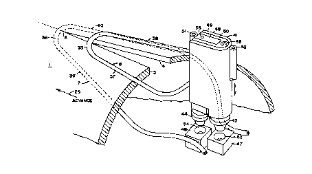
Figs. 8 and 9 illustrate schematically a practical ,
embodiment of the invention illustrated in Fig. 1, other
apparatus conventional in a tube forming mill being omitted.
Thus, a metal sheet or strip 25 is advanced in the direction
of the arrow 26 by conventional advancing or pulling means
CA 02222474 1997-11-26
WO 9P/39789 PCT/US96/07338
-11-
27 and is formed into a tube 1 by forming rolls 28, 29, 30
.and 31 a,nd pressure rolls 32 and 33. In advance of the weld
point 5, where the edge faces 3 and 4 have reached forge
A welding temperature and are pressed together by the pressure
rolls 32 and 33, the edge faces 3 and 4 are held apart by a
fin 34. Thus, when viewed in plan, the edge faces 3 and 4
y~orm a ~w~~ extending from the fin 34 to the weld point 5
with the apex of the "V" at the weld point 5.
Between the roll 31 and the weld point 5, there are
a pair of elongated pancake coils 6 and 7, each with a nose
:35 or 3~6 connecting sides 37, 38, 39 and 40, connected to a
high frequency current source by leads 41. Due to the
presence of the pressure rolls 32 and 33, the nose 35 is
upstream of the weld point 5, but the nose 36 can be
downstream of the weld point 5. The sides 37 and 38 and the
Elides 39 and 40 are spaced from the edge faces 3 and 4 in
t:he direction circumferentially of the tube 1 by distances
which arse small relative to the circumference of the tube 1.
~9ee, for example, U.S. Patent No. 4,197,441.
1'ahen the coils 6 and 7 are electrically energized,
t:he coil 6 causes current flows at the edge faces 3 and 4
which flow in opposite directions and at the exterior
surface of the tube 1 under the sides 37 and 38, and the
coil 7 causes current flow at the edge faces 3 and 4 which
flow in opposite directions and at the interior surface of
the tube 1 above the sides 39 and 40. However, at any given
time, the currents caused at the edge faces 3 and 4 by the
coil 6 f7Low in the same direction as the currents at the
edge faces caused by the coil 7. In other words, the
currents,, at the edge faces 3 and 4 caused by the coils 6
and 7, add. Since heating of the metal at the edge faces 3
and 4 is determined by the formula W=I2R, doubling of the
current causes four times the heating.
of course, the current at the edge faces 3 and 4
flows to and from the weld point 5 and because of the
proximity effect and the fact that the edge faces 3 and 4
become closer together as they approach the weld point 5,
the current at the edge faces 3 and 4 as compared to the
current spaced inwardly of the edge faces 3 and 4, and
CA 02222474 1997-11-26
WO 96/39789 PCT/US96/07338
-12-
hence, the heating, increases. Also, with pancake coils 6
and 7, there is only a minor amount of current
circumferentially of the tube 1.
Since current induced in a part by an induction coil -
must flow in a continuous or closed path, the induced
current flows in the tube 1 in return paths under the sides
or legs 37 and 38 and above the sides or legs 39 and 40
which produce heating of the metal of the tube 1 which
contributes little to the heating of the edge faces 3 and 4.
In order to reduce the concentration of the heating and
resistance of non-useful current paths under the sides 37
and 38 and above the sides 39 and 40, the sides 37-40 can be
widened such as by being provided with conductive plates or
strips conductively connected thereto, such as the plate 42
shown in Fig. 15 connected to the side 37. Such plates
terminate short of the noses 35 and 36 and extend
substantially to the points of connection of the sides 37-40
to the leads 41. The plates are intermediate the sides 37-
40 and the tube 1. Further embodiments of induction coils
for reducing the return path resistance will be described
hereinafter.
Reverting now to Fig. 9, it was previously mentioned
that for the purpose of initially threading the strip 25
into the rolls 28-33, it normally is necessary to raise the
coil 6 and the leads 41, the coil 7 being supported by a
conventional mandrel 43 (see Figs. l0-12) within the tube 1.
Because of this, it is necessary that separable contacts be
used to electrically connect the leads 41 to the coil 7.
One embodiment of such contacts is illustrated in
Figs. 9 and 10, the upper contacts 44 and 45 being shown
partially raised in Fig. 9 and the upper contacts 44 and 45
engaging the lower contacts 46 and 47 in Fig. 10. The coil
7 is connected at its ends to the lower contacts 46 and 47,
and the coil 6 is connected at its ends to the center
conductor 48 and the outer conductor 49 of the leads 41.
The outer conductor 48 is electrically insulated from the
outer conductor 49 by insulation 50. A cooling fluid, such
as water, is supplied through the tubes 51 and 52 which
conductively engage, respectively, the center conductor 48
CA 02222474 1997-11-26
W() 96/39789 PCT/US96/07338
-13-
and the outer conductor 49 and provide the cooling fluid to
the coil. 6.
The lower ends of the contacts 44 and 45 are
received in apertures 53 and 54 which are open at their
bottoms to permit the passage of a dirt flushing fluid, such
as soluble oil, through the apertures 53 and 54 in the
manner described hereinafter. However, flushing of dirt
from the contacts 46 and 47 without passage of the flushing
fluid through the apertures 53 and 54 may, in some cases, be
sufficient. The contacts 44 and 45 also have hollow bores,
and the flushing fluid is supplied thereto, and hence to the
apertures 53 and 54 when the contacts 44 and 45 are raised,
'through a tube 55 and a channel 56 in the center conductor
48. The: contacts 44-47 preferably are made of copper.
Fig. 10 illustrates mounting of the lower contacts
.46 and 47 on the mandrel 43 and in association with other
parts shown in Fig. 9. The contacts 46 and 47 are separated
lby electrical insulation 57 and are secured, in any
conventional manner, to a block of insulation 58 secured to
'the mandrel 43 in any conventional manner. Preferably, the
insulation 58 is high temperature insulation, such as
'.TEFLON .
Figs. 11 and 12 illustrate modifications of the
contact system illustrated in Figs. 9 and 10. Metal blocks
65 and 66, preferably made of copper, each having fluid
passageways, such as the passageways 67 and 68, are provided
between the contacts 47 and 46 and the block of insulation
!58. The passageway 68 provides an outlet for the flushing
fluid supplied to the aperture 53, and the passageway 67
~~ermits cooling fluid to be supplied to the contacts and to
the coil 7 by way of a tube 69. A passageway in the block
66 corresponding to the passageway 68 similarly provides an
outlet for the flushing fluid supplied to the aperture 54,
~3nd a passageway in the block 66 corresponding to the
a 35 passageway 67 similarly permits cooling fluid to return from
1=he coil 7 and to exit from the block 66 by way of the tube
70.
Figs. 13 and 14 illustrate, schematically,
modifications of the apparatus shown in Figs. 8-10. For
CA 02222474 1997-11-26
WO 96/39789 PCTNS96/07338
-14-
ease in illustration, only part of the inner coil 7 is shown
in Fig. 14. It is possible to flush out dirt from between
the contacts when the upper contacts are raised without
having upper contacts 44 and 45 and lower contacts 46 and 47
configured as shown in Figs. 9 and 10. Thus, when the upper
contacts 44a and 45a are raised, a nozzle 59, which is
located adjacent the contacts 44a and 45a and the contacts
46a and 47a can be used to spray a flushing fluid, e.g.
water or soluble oil, between the contacts. In this case,
the upper contacts 44a and 45a can be extensions of the
outer conductor 49 and the inner conductor 48 and the lower
contacts 46a and 47a can be copper blocks. The ends of the
coil 7 are conductively secured to the contacts 46a and 47a,
and the ends of the coil 6 are canductively secured to tabs
48a and 49a which extend from the center conductor 48 and
from the outer conductor 49.
In order to ensure that the edge faces 3 and 4 of
the tube do not contact the outer conductor 49, a spacer
roll 60 having rims 60a and 60b insulated from each other by
electrical insulating material, e.g. an insulating washer
therebetween and a shaft 60c of electrical insulating
material, can be provided as shown in Figs. 13 and 14.
To prevent contact of the coils 6 and 7 with the
tube 1, the sides of the coils 6 and 7 can be provided with
shoes, such as the shoes 61 and 62 on the sides 37 and 39
shown in Fig. 13, made of high temperature electrical
insulating material, e.g. silicon nitride, which engage the
surfaces of the tube 1.
For purposes of controlling the field of the coil 7,
and hence, current distribution in the edge faces 3 and 4,
the mandrel 43 can be provided with a high conductivity
cladding 63, e.g. a copper cladding, in which event, the
mandrel 43 should have a bore 64 for the supply of cooling
fluid to the clad area to reduce heating of the mandrel 43.
Although not preferred, electrical current can also
be supplied to the coil 7 without contacts by coupling the
coil 7 to the coil 6 substantially in advance of the weld
point 5 as illustrated in Figs. 16 and 17. Thus, the coil 7
would be a closed, elongated, electrically continuous loop
CA 02222474 1997-11-26
WO 96!39789 PCT/US96/07338
-15-
and current would be induced therein by the portions 37a and
38a of t:he upper loop 6 which extend into the gap between
the edge: faces 3 and 4 and into close proximity t~ the coil
.. 7. Whi7.e the ends of the coil 6 would be connected to the
leads 47., no connections of the coil 7 to the leads 41 would
be necessary.
Coupling between the portions 37a and 38a of the
coil 6 and the coil 7 can be increased by inserting a core
71 of magnetic material, e.g. a ferrite core, as shown in
Figs. lE~ and 17.
Fig. 18 illustrates in perspective the embodiment of
the invention, also shown in Fig. 6, in which metal fins 18
and 19 acre welded to a metal tube 20 as the tube 20 and the
fins 18 and 19 are advanced and the edge faces 16 and 17 and
the portions of the tube 20 nearest to the edge~faces 16 and
17 are heated by electrical currents induced therein by the
pancake induction coils 6d and 7d.
In the embodiments described hereinbefore, the edge
faces 3 and 4 or 1.6 and 17 and the facing portions of
upturned portions 20 and 21 have been heated to welding
temperature by pancake coils which are preferred in the case
of the welding of a tube from a folded sheet because it is
not necessary that pancake coils have a size close to the
size of the tube which, in some cases, can be relatively
large. Such pancake coils can be used alone, as described
hereinbe:fore, or can be combined with other induction coils,
one of which encircles the tube and the other of which is
'within t:he tube and closely follows the inner surface of the
tube. Htowever, such other induction coils can also be used
'without the pancake coils in the welding of the edge faces
of a tube.
Fig. 19 illustrates schematically the welding
together of the edge faces 3 and 4 of a tube 1 using both
the pancake coils 6 and 7 described in connection with Figs.
1 and 8-~10 and a pair of outer and inner induction coils 72
and 73, the outer coil 72 encircling the tube 1 and being in
close proximity to the outer surface and periphery of the
tube 1 a.nd the inner coil 73 encircling the longitudinal
axis of the tube 1 and being in close proximity to the inner
CA 02222474 1997-11-26
WO 96/39789 PCT/US96/07338
-16-
surface and inner periphery of the tube 1. Such coils 72
and 73 will sometimes be identified as tube periphery coils
to distinguish them from pancake coils.
The pancake coils 6 and 7 are connected to the leads
41 as previously described and act in the manner previously
described to induce heating currents in the edge faces 3 and
4. However, if desired, such coils 6 and 7 can be omitted.
Tube periphery coil 72 is conductively connected at
its ends to the conductive leads 48 and 49 and tube
periphery coil 72 is conductively connected at its ends to
the leads 48 and 49 by the contacts 44a and 45a. The coil
73 is supported by a mandrel, such as the mandrel 43 (not
shown in Fig. 19) in any conventional manner which does not
produce a short-circuit between portions of the coil 73.
1~or example, the mandrel can be encircled by a ring of
electrical insulation on which the coil 73 is mounted. It
will be observed that all the coils 6, 7, 72 and 73 are
connected electrically in parallel.
The coils 72 and 73 will produce electrical currents
at the edge faces 3 and 4 which, at any given time, flow in
'the same direction as the electrical currents produced on
the edge faces 3 and 4 by the coils 6 and 7. Thus, the
currents add on the edge faces 3 and 4. Fig. 23 indicates
schematically the current flows in the coils 72 and 73 at
any given time and in the tube 1 by the arrows and
arrowheads.
Fig. 24 illustrates the electrical current flows
produced in the tube 1 at any given time by pancake coils 6
and 7 by the arrows, circles and plus signs and the relative
heating caused by such current flows by the shaded areas.
Again, it will be observed that the currents produced by the
two coils 6 and 7 add at the edge faces 3 and 4.
As pointed out earlier in this description of the
invention, it would be expected by those skilled in the art
that if two coils, an inner and outer coil, were used to .
produce the heating of the faces to be welded together,
rather than a single coil, the total amount of power
required with two coils would be the same as the amount of
power required with a single coil. As discovered from the
CA 02222474 1997-11-26
WCI 96/39789 PCT/US96/07338
-17-
experiments conducted and reported hereinbefore, this is
not
the casE~, and instead, a smaller amount of power is required
which leads to a higher electrical efficiency.
While not intending to be bound by a theory as to
why there is improved electrical efficiency with two
induction coils, it is believed that the improved efficiency
is obtained as a result of the fact that there are two
separate: return paths for the current flowing at the edge
faces or portions to be heated to welding temperature. As
1o pointed. out hereinbefore, the current induced by induction
coils in a part to be heated must flow in a continuous, or
closed, path. The portion of the path that follows the edge
faces or portions is useful, since it heats such edge faces
or portions to welding temperature, but the remaining
portion or portions of the path are substantially wasteful
of electrical energy since they are spaced from the edge
faces or portions to be heated.
Fig. 22 illustrates schematically the current flows
when a ~;ingle induction coil which surrounds the tube axis,
either internally or externally of the tube 1, induces the
heating current in the tube 1. Thus, all of the induced
current flows along the edge faces 3 and 4 in opposite
directions as indicated by the arrows 74 and 75. However,
due to proximity effect, which causes the most of the return
path current to be as close as possible to the induction
coil, tree return current path will be restricted essentially
to either the outside or inside of the tube depending upon
whether an external or internal induction coil is used. For
example, if only an external coil, e.g. 72 (see Fig. 23),
is
used, most of the return current will flow at the external
surface of the tube 1 along the paths and in the directions
indicats:d by the arrows 76 and 77 in Fig. 22. However, due
to the fact that there is a potential difference between
the
edge faces 3 and 4, a small portion of the return current
will flow at the internal surface of the tube 1 as indicated
by the arrows 78 and 79.
Assume that the desired current at the edge faces 3
and 4 isc 1000 amperes and that an external induction coil 72
used anct for purpases of illustration, it is reasonable to
CA 02222474 1997-11-26
WO 9Cr/39789 PCT/US96/07338
-18-
assume that the resistances of the return paths externally
and internally of the tube 1 are substantially equal, e.g.
tin the order of 0.1 ohm. The heating power at the edge
faces would be I2 Re watts where Re is the resistance of the
edge faces and which is on the order of 0.1 ohm. The wasted
return path power is then, Iis Ris + Ios Ros where Iis is
the internal surface current, Ios is the external surface
current, Ris is the internal surface resistance of the tube
1 and Ros is the external surface resistance of the tube 1.
Because of the proximity effect, most of the return current
will flow at the outer surface of the tube 1 with an
external induction coil. From experience, it has been found
that for illustration purposes, it can be assumed that in
such case 900 amperes of current would flow at the external
surface and 100 amperes of current would flow at the
internal surface. Therefore, the wasted power would be 9002
Ros + 1002 Ris. With Ros = Ris, the value is 820,000 (Ros
or Ris) watts. With Ris and Ros approximately equal to Re
and approximately 0.1 ohm, the useful power is 100,000 watts
and the wasted power is 82,000 watts or 82% (82,000/100,000)
of the useful power.
Similar analysis applies when only an internal
induction coil 73 (see Fig. 23) is used, and the conclusions
are similar.
However, when Fig. 22 is compared with Fig. 23, it
caill be seen that with an internal coil 73 and an external
coil 72 (Fig. 23), the return currents follow two different
paths, indicated by the arrows 80 and 81 which are radially
separated both by reason of the proximity effects of the
coils 72 and 73 and by reason of skin effect with high
frequencies. Because there are two induction coils 72 and
73, the return currents, which, in total, equal the current
at the edge faces can be more nearly equal on the internal
and external surfaces of the tube 1 as has been found from
experiment, and can be adjusted by adjusting the electrical
energy supplied to the coils 72 and 73. Thus, the return
current portions of the edge face current are divided
between the internal and external surfaces of the tube 1 so
that the effective resistance of the return paths is one-
CA 02222474 1997-11-26
WO 96/39789 PCT/US96/07338
-19-
half. Assume, for example, that the outside and inside
:return currents are respectively 600 amperes and 400 amperes
and the resistances Re, Ris and Ros are as assumed to be 0.1
ohm, they wasted power is 6002 Ros + 4002 Ris = 520,000 (RPis
or Ros) or 52,000 watts which is only 63~ of the wasted
lpower when a single induction coil, 72 or 73 is used. In
other words, there is a substantial reduction in electrical
lpower required to perform the desired welding, i.e. 152,000
~~aatts with internal and external induction coils vs. 182,000
watts with only an internal or an external induction coil.
A similar analysis applies when pancake coils 6 and
'7 are used. Fig. 24 illustrates by the shaded areas the
current paths when two pancake coils 6 and 7 are used.
'.thus, th.e shaded areas 82 and 83 indicate the useful current
:Flow on the edge faces 3 and 4, the shaded areas 84 and 85
:indicate the return current flow for the current induced by
the coil 6 and the shaded areas 86 and 87 indicate the
:return current flow for the current induced by the coil 7.
Again, d.ue to the fact that the current at the edge faces 3
~3nd 4 follows two different return paths, paths 84 and 85
:Eor the current induced by the coil 6 and paths 86 and 87
:Eor the current induced by the coil 7, there is a
;significant reduction in wasted power and increase in
electrical efficiency.
A further possible reason for the increase in
electrical efficiency is suggested by a comparison of Figs.
22 and 23 from which it will be noted that with a single
:induction coil 72 outside the tube (Fig. 22), there are
:return currents 78 and 79 on the inner surface of the tube 1
as well as return currents 76 and 77 on the outer surface of
'the tube 1. Thus, when a single induction coil, either
around the tube or a single pancake coil, there are return
currents on the surface of the tube 1 nearest the inducing
coil and on the opposite surface of the tube 1, the latter
:return currents being due to the potential difference
lbetween the edge faces 3 and 4. When a second induction
coil is used, e.g. the coil 73 (Fig. 23), the return current
caused by one coil at the surface nearest the second coil is
opposed by the current in the latter surface caused by the
CA 02222474 1997-11-26
WO 96/39789 PCT/US96/07338
-20-
second coil or "bucked out'°.
As previously pointed out, most of the return
current follows a path as close as possible to the induction
coil. From the foregoing analyses, it also will be apparent
'that the wasted power can be reduced if the resistance of
the return paths is reduced. By increasing the width of the ,
inducing coil adjacent the return current paths, the return
current spreads out over a wider area and not only lowers
the peak temperature of the metal traversed by the return
current but also reduces the resistance of the return
current paths.
One method of increasing the width of the inducing
coil is shown in Fig. 15, and other embodiments will be
described in connection with Figs. 25-29.
One practical embodiment of the invention is
illustrated in Figs. 25 and 26 and uses the principles
described in connection with Figs. 8 and 9. In Fig. 25, a
pair of leads 88 and 89, such as copper plates, separated by
insulation 90, such as a sheet of TEFLON, are connected to a
high frequency electrical power source 91 in a conventional
manner and by way of a pair of blocks 92 and 93 having
cooling water channels and conductively secured to the leads
88 and 89, such as by brazing. Cooling fluid, such as
water, is supplied to the blocks 92 and 93 by way of tubes
94 and 95, and flows out of the blocks 92 and 93 and onto
the external surfaces of the leads 88 and 89 through tubes
96, both blocks 92 and 93 having tubes 96 but only the tubes
96 for the box 93 being visible in the drawings.
A first contact 97, such as a copper block with
cooling water channels, is fixedly mounted on a block 98 of
insulation, and the insulating block 98 is secured to and
supported by a conventional mandrel 99.
A second contact 100, such as a copper block with
cooling water channels, is slidably mounted on the
insulating block 98 so that it can move toward and away from ,
the lead 89. The second contact 100 can be urged toward the
lead 89 by a spring or can be moved toward and away from the
lead 89 by gas operated piston and cylinder assembly 101
secured in a fixed position on the insulating block 98 and
CA 02222474 1997-11-26
WO 9.6/39789 PCT/US96/07338
-21-
having a: piston rod 102 secured to the contact 100. Such
contact arrangement permits movement of the leads 88 and 89
'upwardly from the positions shown in Figs. 25 and 26 for
threading purposes described hereinbefore.
Cooling fluid, such as water, is supplied to the
contacts 97 and 100 through tubes 103 and 104.
An outer pancake coil 105 is mechanically and
electrically conductively secured, at opposite ends, to the
:Leads 88 and 89. Accordingly, when the leads 88 and 89 are
moved upwardly, the coil 105 is also moved upwardly, away
~Erom the path of the tube 1. The coil 105 has a rectangular
cross-section, as distinguished from the circular cross-
:~ection of the coils previously described, to increase the
volume, and hence, to reduce the resistance, of the return
current paths. Thus, the dimension of the legs 105a and
105b in 'the peripheral direction of the tube 1 is large
relative to the dimension of the legs 105a and 105b
i:ransverse to such direction. The coil 105 is tubular to
provide .a cooling fluid circulation duct or channel 106 to
which cooling fluid is supplied and removed through the
tubes 10'7 and 108.
The inside pancake coil 109 is connected at ;t~
opposite ends respectively to the contact blocks 97 and 100
~>o that :it is electrically in parallel with the pancake coil
7.05. Although the coil 109 could have a dimension in the
direction of the periphery of the tube 1 the same as coil
1.05 and could be tubular like the coil 105 so as to provide
a water cooling channel therein, the legs 109a and 109b can
be much wider in the peripheral direction of the tube 1 than
t:he legs 105a and 105b of the coil 105 to reduce the
resistance of the return current paths. Instead of being
tubular 7Like the coil 105, the coil 109 can have a plurality
- of fluid,, e.g. water, circulating tubes 110 conductively
attached to,the side thereof remote from the tube 1, such as
by brazing.
figs. 27 and 28 illustrate alternative
configurations for the pancake coils 105 and 109. Thus, the
coil 111 has legs llla and lllb which are relatively wide in
the direction of the periphery of the tube 1 and is cooled
CA 02222474 1997-11-26
WO 96./39789 PC'T/US96/07338
-22-
by a tube 112 conductively secured thereto and through which
a cooling fluid, such as water is circulated. The nose llle
can have the same width dimension as the legs llla and lllb
or can have a different width dimension.
What is important in increasing the electrical
efficiency of the welding operation for both a single
induction coil or two induction coils is that the portions
of the induction coils which overlie the return current
paths be wide enough to substantially increase the width of
the return current paths, and hence, reduce the resistance
of such paths. This applies both to pancake coils and
induction coils encircling the axis of the tube. In the
case of pancake coils, all of the return currents underlie
the coil. In the case of encircling induction coils, the
return currents underlie only the portions of the coils
which are not adjacent the edge faces 3 and 4 to be heated
to welding temperature.
Accordingly, the portions of the coils overlying the
return current paths should have a width, in the direction
of the tube periphery for a pancake coil and in the
direction of the tube axis for an encircling coil, which,
substantially increases the width, and hence, the volume of
the return current path and its resistance, as compared to
induction coils having a circular cross-section.
Thus, it is known in the art that the current
induced in a metal part by an induction coil is the largest
where the coil, or portion thereof, is nearest the metal
part. When the coil is circular in cross-section, the
maximum current flows where the circumference or periphery
of the coil is nearest the metal part and tapers off as the
circumference increases in spacing with respect to the metal
part. Therefore, to distribute the current flow over a
wider path in the metal, and hence, decrease the resistance
and power loss due to the return current, i.e. the current
in paths other than along the surfaces of the parts where
they are to be welded together, the portions of the coil
adjacent the return current paths should have relatively
wide surfaces facing and equidistant from the metal.
For example, the legs 105a and 105b in Fig. 25 have
CA 02222474 1997-11-26
WCI 9ti/39789 PCT/US96/07338
-23-
a width w in the direction of the periphery of the tube 1,
~nnd hence, transverse to the direction of advance of the
'tube 1, and radially inward surfaces, such as the surface
. :105c, facing the tube 1 which are substantially equidistant
:from the outer surface of the tube 1. The legs 105a and
:L05b are generally parallel to the edge faces 3 and 4 which
have a gap 113 therebetween prior to the weld point 5. The
spacing between the edge faces 3 and 4 where they first
underlie the upstream of the coil 105 can be in the range
~Erom seven-eighths to one-and-one-quarter inches. Depending
upon the thickness of the metal of the tube 109, which can,
iEor example, be in the range from about 0.125 inches to
about 0.625 inches, the length of the gap 113 from the
upstream end of the coil 105 can be in the range from about
i=wo inches to eight inches, thicker metals requiring a
longer length to obtain the desired heating of the edge
i:aces, for example, to 2500F for steel which is above the
(:urie point for steel. The reference depth for steel at 100
)E:Hz is about 0.08 inches and at 400 kHz is about 0.04 inches
with a temperature about 1400F.
.As pointed out in said patent No. 4,197,441, the
inner sides 105d and 105e of the legs 105a and 105b should
be spaced respectively from the edge faces 3 and 4 by at
7.east te:n times the reference depth. Thus, at the upstream
end of tike coil 105 the spacing between the sides 105d and
7.05e would be at least seven-eighths inches plus ten times
t:he reference depth. Of course, the coil 105 need not be
rectangular as shown in Fig. 25, i.e. have equal spacing
throughout their lengths in the direction of advance, and
c:an be closer together at their downstream ends and can, for
example, have the sides 105d and 105e parallel to the edge
faces 3 and 4. To obtain a significant increase in
. efficiency by reason of the width of the legs 105a and 105b,
t:he widi=11 w of the surfaces of the legs, e.g. 105c, nearest
t:he tube 109, should be at least twice the spacing of the
sides 10!5d and 105e from the edge faces 3 and 4. The
following Table I will further illustrate the relationships:
Table I
I-',feating 1lower Reference Depth Spacing of 'Width of leg
CA 02222474 1997-11-26
WO 96/39789 PCT/US96/07338
-24-
Frequency 2500°F sides 105d surface
and 105e from nearest
faces 3 and 4 tube 109
100 KHz 0.08 in. min 0.8 min 1.6 in. ,
400 KHz 0.04 in. min 0.4 min 0.8 in.
Preferably, the spacing of the sides 105d and 105e ,
from, respectively, the edge faces 3 and 4 does not exceed
about 30 times the reference depth, and the width w of the
surfaces of the legs 105a and 105b does not exceed about 6
l0 times such spacing because larger spacing and widths produce
an insubstantial improvement in electrical efficiency and
increase the cost of the coil and the difficulties in
mounting the coil. The maximum width also depends on the
width and thickness of the metal at each side of the gap 11,
~e.g. the diameter of the tube 109 and the thickness of the
tube metal. In general, the width should be about one to
three inches, a greater width being used when the metal is
thick, e.g. 0.625 inches and a narrower width being used
when the metal is thin, e.g. 0.125 inches.
The nose portion 105f of the coil 105 can have the
same dimension in the direction of advance of the tube 109
as the width dimension of the legs 105a and 105b or can have
a different dimension, i.e. larger or smaller.
Similar considerations apply to an induction coil
encircling the tube 109 or within the tube 109 and
encircling its axis (Fig. 23). Thus, such a coil would have
a width, in the direction of advance of the tube 109, for
the surface thereof facing the tube 109 which is at least
twenty times the reference depth.
An induction coil designed as taught hereinbefore
will increase the electrical efficiency of induction welding
even when only one induction coil is used, i.e. when a
second induction coil at the opposite surfaces of the metal
parts as in the invention described hereinbefore is omitted.
When two induction coils are employed, e.g. one outside a ,
tube and one inside a tube, it is preferred that both coils
have the characteristics described.
Fig. 29 illustrates schematically the major current
paths in the metal tube 1 when induction coils, such as the
CA 02222474 1997-11-26
WO 96/39789 PCT/US96/07338
-25-
coil 11~. with wide legs llla and lllb, are used to induce
currents in the tube 1. When Fig. 29 is compared with Fig.
24, the latter showing the major current paths when
induction coils of circular cross-section are used, it will
be observed that the major current paths at the faces 3 and
4 along which the useful heating currents flow are
essentially the same with both types of coils. However, the
return rind essentially non-useful current paths 84-87 in
Fig. 24 are relatively narrow and hence, of relatively high
resistance whereas with the wide leg coils 111 (Fig. 29) the
return current paths are relatively wide and hence, of lower
resistance. Accordingly, with wide leg coils 111, the
wasted electrical energy is, less than it is with coils with
narrow legs.
15. It will also be observed from Fig. 29 that the
surface:a of each of the legs llla and lllb nearest the tube
1 lie in planes which are substantially parallel to the tube
surfacea and each such surface has a substantially constant
spacing with respect to the adjacent tube surface. However,
while preferred, it is not necessary that the spacings of
each such surface with respect to the adjacent tube surface
be equal.
Although in the preceding embodiments, the various
induction coils have been shown connected to the power
2-'i source electrically in parallel, the coils 6 and 7 can be
connected electrically in series as shown in Fig. 20 in a
manner .obvious to those skilled in the art, and the coils 72
and 73 can be connected electrically in series as shown in
Fig. 21 in a manner obvious to those skilled in the art.
Although single turn pancake coils and single turn
tube periphery coils have been illustrated and described,
any one or more of the coils can have multiple turns.
Although preferred embodiments of the present
invention have been described and illustrated, it will be
3!5 apparent to. those skilled in the art that various
modifications may be made without departing from the
principles of the invention.