Note: Descriptions are shown in the official language in which they were submitted.
CA 02222604 1997-11-27
W O 96~9578 PCTrUS9G/'~7Y7L
J TORCH A8BEMBLY
BACK~KOUN~ OF THB l~.v~,lON
This invention was made with government support
under F33615-93-C-2355 awarded by the United States
Air Force. The U.S. government has certain rights in
this invention.
Field the Invention
The invention relates to an assembly for ignition
of gas turbine combustors. In addition, this
invention relates to devices for continuous
stabilization/re-ignition of lean low N0x combustion.
This invention also relates to igniters for use in
place of conventional spark plug fuel ignition
systems.
BRIEF DESCRIPTION OF RELATED ART
Commercial aircraft gas turbine combustors
utilize combustor wall mounted igniters, typically a
spark plug, for combustor light-off. This requires
the presence of fuel close to the wall. Inasmuch as
combustion of fuel near the wall during full power
operation tends to raise the wall temperature,
combustor designs tend,to be a compromise between
ignition and operational requirements. Thus there
have been numerous attempts to achieve ignition away
from the wall. Ideally, ignition should be achieved
right at the fuel source so that ignition of the
initial fuel flow is possible. This avoids the
necessity to dump unburned fuel into the combustor
prior to ignition (creating the potential for hot
starts or explosive detonations with consequent damage
CA 02222604 1997-11-27
W O 96/39S78 PCT~US9G/~7Y/
to the turbine) and enables the use of spray patterns
which keep fuel away from the combustor walls.
Accordingly, there has been interest in
integrating the ignition source into the fuel
injector. For example, U.S. patent 4,938,019
describes a fuel nozzle with an integrated spark plug
igniter assembly and U.S. patent 4,825,658 describes a
fuel nozzle with a catalytic glow plug igniter
assembly. Such designs have major drawbacks which
limit utility. For example, a spark plug integrated
into an injector is subject to fouling if wetted by
liquid turbine fuel, rendering it inoperative. In
addition, size limitations reduce spark plug life. On
the other hand, although the glow plug of U.S. Patent
4,825,658 eliminates the fouling problem of spark
plugs, the glow plug is designed such that the return
flow of the recirculating flow downstream of the
injector contacts the hot glow plug surface resulting
in ignition of the downstream recirculating gases.
Inasmuch as the initial direction of the incoming
fuel-air flow from the swirler is away from the glow
plug considerable fuel can travel downstream before
sufficient fuel is injected to increase the
recirculation zone fuel concentration high enough at
the glow plug to allow ignition. Thus explosive
detonation is possible as is the case with
conventional spark igniters presently used in aircraft
gas turbine engines. Advantageously, fuel should be
ignited immediately as it enters the combustor.
In the present invention atomized fuel entering a
gas turbine combustor is reliably ignited as it enters
the combustor by contact with a continuous pilot flame
projected into the combustor distal to the combustor
walls, at a location to ignite the incoming fuel. The
present invention offers the advantages of away-from-
CA 02222604 1997-11-27
W O 96/39578 PCTAUS96/07972
the-wall ignition coupled with continuous flame
stabilization by providing for projection of the pilot
flame into a combustor, whether from the liner wall or
from the combustor centerline, such as if mounted
within a fuel nozzle.
SUMMARY OF THE l~.v~..lON
The invention comprises an improved torch assembly
for ignition of fuel in admixture with air within a gas
turbine combustor, which comprises:
a tubular chamber containing a hot surface,
preferably catalytic, ignitor, means for atomizing fuel
into admixture with air, a primary zone for fuel
vaporization, a secondary zone for air addition and
partial fuel reaction, and an exit opening for pilot
flame establi~h ?nt and projection into the combustor.
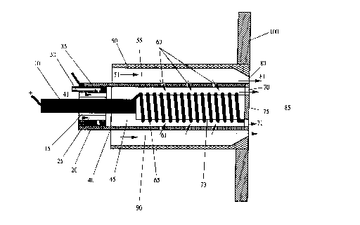
BRIEF DESCRIPTION OF THE DR~WING
The drawing shows a partial cross-sectional side
view of an embodiment of the catalytic ignitor/flame
stabilizer torch assembly of the invention having an
axially mounted surface ignitor.
DE~TT~T~n DE8CRIPTION OF T~E ~K~KRED
EMBODl~ . S OF THE lNV~. lON
Those skilled in the art will gain an appreciation
of the invention from reading the following description
of the preferred embodiments of the invention in
conjunction with a viewing of the accompanying drawing.
With reference to the drawing, which is a cross section
of an embo~; ?nt assembly of the invention as seen from
the side, torch assembly 90 comprises tube 40 shown
situated inside an outer coaxial tube S0 which may be
an inner wall of a fuel nozzle or as shown, a fitting
on combustor liner wall 100. The outer coaxial tube 50
which houses the assembly carries air flow 51 which may
be preferably swirled in the space 55 around the
CA 02222604 1997-11-27
W O 96~9578 PCT~US96/07972
assembly and out through restriction 80 at the end of
the outer tube 50 and into the gas turbine combustor,
not shown. The gas turbine combustor, such as the
example described in U.S. Patent 3,975,141 which is
5 incorporated herein by reference thereto, can have a
variety of configurations and air flow patterns inside
the combustor. Fuel/air manifold 20 which restricts
the flow of air 41 entering the assembly through
passageways 25. Fuel/air manifold 20 includes a fuel
10 tube 30 which provides fuel to the manifold. Fuel
injection ports 35 provide partially atomized fuel to
the high velocity air flows 41 in passageways 25. In
the preferred configuration, the fuel is atomized and
partially vaporized by air flowing through the
15 passageways 25 in the manifold, but other atomization
t~chn;ques may be used such as for example atomizers
described in U.S. patents 4,255,777; 4, 380,786;
4,581,675; 4,991,774; and 5,093,602, all of which are
incorporated herein by reference thereto. The
20 partially atomized fuel is carried by the air flow into
chamber 45 inside the assembly where the fuel is
further vaporized before passing into contact with
igniter 65. Fuel/air manifold 20 also serves as a
mount for electrode 10 which supplies power to ignitor
25 65. An electrically non-conductive layer 15 isolates
the electrode 10 from the fuel/air manifold 20. The
electrode 10 is connected to an electrical power
source, not shown, exterior to the combustor. The
electrode 10 is electrically connected to the surface
30 ignitor 65. In preferred embodiments of the invention,
the ignitor is a resistance heating element which
supports an oxidation catalyst on the surface or an r
electrically conductive metal oxidation catalyst such
as platinum or an electrically conductive oxide t
ceramic. For example, the element 65 can be a 0.035 mm
CA 02222604 1997-11-27
W O 96/39578 PCT~US96/07972
Hastelloy-X resistive wire coated with any ignition
catalyst known in the art, or element 65 can be a
platinum structure 0.020 mm thick and machined to
provide a reasonably long conductive path. In the
J 5 embodiment shown, the ignitor 65 is in the form of a
coil of oxide hardened platinum wire mounted on ceramic
support 73. For long-life and durability, the element
65 is itself a catalyst which can provide a high
t- ~rature surface for fuel pre-reaction before
10 downstream combustion in region 85 after the exit of
the assembly. The temperature of the element is most
readily monitored and controlled either by measu~l- ~nt
of element resistance or by a temperature-sensing
device such as a thermocouple or an infrared detector.
15 In the drawing the ignitor element 65 is positioned
axially down the center of the tube 40 in the space 45
ext~n~ing to or close to the tube exit aperture 70, but
the ignitor 65 need not, of course be in any particular
shape or configuration as long as it presents a surface
20 for contact with and ignition of the hydrocarbon fuels.
The terms "fuel" and "hydrocarbon" as used in the
present invention not only refer to organic compounds,
including conventional li~uid and gaseous fuels, but
also to gas streams cont~;ning components such as
25 carbon monoxide, organic compounds, or partial
oxidation products of carbon containing compounds. In
the preferable configuration, a durable electrical
connection which can sustain high temperatures is made
through a conductive end piece 75 from the ignitor
30 element to the assembly tube 40. An electrical lead
which provides the return lead to the power source can
~ then be attached to the upstream end of tube 40. This
provides an electrical circuit for providing a -~n~ of
externally heating the ignitor. In the circuit, the
35 ignitor element 65 must be the region of highest
CA 02222604 1997-11-27
W O 96~9578 PCTAUS96/07972
resistance in order to ensure that when electrical
power is supplied through the leads the ignitor element
is heated to a much higher temperature than the other
parts of the circuit path.
The ~xr~n~ion of the flow of fuel and air out of
the fuel/air manifold 20 into the inner lumen 45 of the
assembly provides a low pressure region in the lumen 45
to allow for staged air addition into the assembly
further downstream through small air addition holes 60
in the assembly tube. In the preferable embodiment,
the air flow 61 through the side holes 60 is enhanced
by the downstream restriction 80 in the outer housing
tube which keeps the pressure in the space 55 outside
the assembly relatively high in ~ _~rison to that in
the inner lumen 45. The air flow 61 through the air
addition holes 60 serve a dual purpose of controlling
the temperature distribution along the surface of the
ignitor element 65 and of increasing the air to fuel
ratio to enhance reaction of the vaporized fuel and to
allow for combustion of the admixture after exiting
into the gas turbine combustor chamber in region 85.
In the preferable embodiment, the flow across the
ignitor element 65 is maintained at a high enough
velocity to limit combustion inside the assembly and
thus increase durability of the ignitor element 65.
Combustion of the partially reacted fuel is then
stabilized in the combustion zone inside the gas
turbine combustion chamber in region 85. Although air
flow 81 and tube 50 are not required in all
applications, combustion stabilization in region 85 can
be enhanced by swirling the additional flow 81 which
exits from an outer passage around the assembly exit as
shown in the figure. With continuous operation,
ignitor element 65 allows for stable combustion of a
combustor at leaner overall fuel/air admixtures than
CA 02222604 1997-11-27
W O 96/39578 PCT~US9G~ 7
otherwise possible. The hot partialiy-reacted flow 71
passing through the assembly exit 70 travels at
relatively high velocities which insures that the pilot
flame in region 85 extends well into the combustion
J 5 chamber and provides a robust source of ignition for
other fuel injected into the gas turbine combustor.
Torches of the present invention may be operated with
either overall lean or overall rich fuel/air mixtures
as dictated by the requirements of the combustor with
10 which it is used. In one preferable embodiment, the
assembly 90 would be placed along the center axis of a
main air-blast fuel nozzle, which sprays into the
primary combustion zone of a gas turbine combustion
chamber. In this embodiment, the torch provides an
15 ideal source of ignition in region 85 for the entire
fuel flow even at lean combustor operating conditions.
The use of a catalytic ignitor element 65 in the
assembly enhances the ability of the assembly 90 to
work well at lean conditions and enables stable
20 operation of the torch after initial light-off with
little or no electrical power.
The operation of the assembly 90 can be
appreciated by referring again to the drawing. The
high velocity air flow 41 through the passageways 40 in
25 the fuel/air manifold 20 carries the partially atomized
fuel into the lumen 45 inside the assembly and over the
electrically-heated surface ignitor element 65. After
the fuel is vaporized and partially reacted in intenal
space 45 of the assembly 90, air flow 61 is added
30 through the air addition holes 60 through the assembly
tube 40 from the outer space 55 around the assembly go.
The added air 61 mixes with the fuel/air admixture over
the ignitor 65 surface and furthers partial reaction of
r the fuel over the hot, preferably catalytic, ignitor
35 element 65. The fuel/air admixture is continually
CA 02222604 1997-11-27
W O 96/39578 PCT~US96/07972
heated and partially reacted over the ignitor 65
surface until it passes with a relatively high velocity
into the gas turbine chamber in region 85 where it
burns to completion and provides a robust pilot flame
for igniting fuel injected into the gas turbine
combustor chamber. Because the ignitor element 65 can
be electrically heated before fuel is injected into the
assembly 90 or into the gas turbine chamber, the torch
assembly 90 can provide almost instant ignition of both
the assembly fuel as well as the main fuel to the gas
turbine combustion chamber.
In torch assemblies of the invention the pilot
flame is established and stabilized downstream of the
assembly. Swirling the flow 51 through an outer
passage enhances flame stabilization in region 85.
During starting of a gas turbine engine, typically the
element 65 is heated to a temperature above the ~;n;~
temperature required for ignition at the given air flow
condition prior to introduction of fuel thus assuring a
rapid light-off. After light-off, electrical power
and/or fuel flow to the element 65 may be controlled to
maintain the element at a temperature below a safe
value for the materials used. Reduction of fuel flow
during operation allows the torch to to operate with
m;~i ~l production of NOx. Typically, electrical
heating is discontinued after light-off though
continued controlled heating may be utilized to provide
near instantaneous relight in those situations where
aircraft operation, for example, could result in engine
flame-out such as by ingestion of water into the
engine.
Those skilled in the art will appreciate that many
modifications of the preferred embodiment described
above can be made without departing from the spirit and
scope of the invention.