Language selection

Search

Patent 2222635 Summary

Third-party information liability

Some of the information on this Web page has been provided by external sources. The Government of Canada is not responsible for the accuracy, reliability or currency of the information supplied by external sources. Users wishing to rely upon this information should consult directly with the source of the information. Content provided by external sources is not subject to official languages, privacy and accessibility requirements.

Claims and Abstract availability

Any discrepancies in the text and image of the Claims and Abstract are due to differing posting times. Text of the Claims and Abstract are posted:

  • At the time the application is open to public inspection;
  • At the time of issue of the patent (grant).
(12) Patent: (11) CA 2222635
(54) English Title: ARRANGEMENT OF CONTACT PAIRS OF TWIN CONDUCTORS AND OF CONDUCTORS OF A MULTI-CORE CABLE FOR THE PURPOSE OF REDUCING CROSSTALK
(54) French Title: MONTAGE DE PAIRES DE CONTACTS DE CONDUCTEURS JUMELES ET DE CONDUCTEURS D'UN CABLE A AMES MULTIPLES, VISANT A REDUIRE LA DIAPHONIE
Status: Expired and beyond the Period of Reversal
Bibliographic Data
(51) International Patent Classification (IPC):
  • H01B 7/00 (2006.01)
  • H01B 7/10 (2006.01)
  • H01B 11/00 (2006.01)
  • H01B 11/04 (2006.01)
(72) Inventors :
  • GWIAZDOWSKI, MICHAEL (Germany)
(73) Owners :
  • KRONE GMBH
(71) Applicants :
  • KRONE GMBH (Germany)
(74) Agent: G. RONALD BELL & ASSOCIATES
(74) Associate agent:
(45) Issued: 2002-08-20
(22) Filed Date: 1997-11-27
(41) Open to Public Inspection: 1998-06-10
Examination requested: 2000-02-15
Availability of licence: N/A
Dedicated to the Public: N/A
(25) Language of filing: English

Patent Cooperation Treaty (PCT): No

(30) Application Priority Data:
Application No. Country/Territory Date
196 51 196.8 (Germany) 1996-12-10

Abstracts

English Abstract


An arrangement of contact pairs of twin conductors and
of conductors of a multi-core cable for the purpose of reducing
crosstalk, in which the contact pairs of the twin conductors or
the conductor pairs define mutually parallel, non-congruent
areas F1,2; F3,4; F5,6; F7,8, and the twin conductors or, conductor
pairs are arranged on electric equipotential lines of their
neighbouring twin conductors.


Claims

Note: Claims are shown in the official language in which they were submitted.

THE EMBODIMENTS OF THE INVENTION IN WHICH AN EXCLUSIVE PROPERTY
OR PRIVILEGE IS CLAIMED ARE DEFINED AS FOLLOWS:
1. An arrangement of conductors for the purpose of
reducing crosstalk, comprising pairs of the conductors disposed
parallel to one another and defining non-congruent areas, said
pairs of the conductors being arranged on electric equipotential
lines of their neighbouring pairs of the conductors.
2. The arrangement as claimed in claim 1, wherein
said pairs of said conductors have the same spacing "a" in each
case.
3. The arrangement as claimed in claim 2, wherein
each of said pairs of said conductors includes a forward
conductor and a return conductor, each of said forward
conductors being arranged in a plane and each of said return
conductors being arranged in a plane.
4. An arrangement in accordance with claim 3, wherein
three pairs of said pairs of the conductors are provided and
each of said pairs of conductors being arranged on electric
equipotential lines of adjacent pairs of conductors; said planes
of said forward and return conductors are substantially
parallel.
5. An arrangement in accordance with claim 1, wherein
a first conductor of one of said pairs is spaced an unequal
distance from said conductors of an adjacent of said pairs.
6. An arrangement in accordance with claim 1, wherein
conductors of a first pair of said pairs of the conductors form
a first plane; conductors of a second pair of said pairs of the
conductors form a second plane, said second and said first
planes are substantially parallel.
7

7. An arrangement in accordance with claim 1, wherein
three pairs of said pairs of the conductors are provided and
each of said pairs of conductors being arranged on electric
equipotential lines of adjacent pairs of conductors.
8. A multi-core cable comprising a multiplicity of
conductors providing conductor pairs defining mutually parallel,
non-congruent areas, said conductor pairs being arranged on
electric equipotential surfaces of their neighbouring conductor
pairs.
9. A multi-core cable, according to claim 8, further
comprising connection means for connecting said conductor pairs
to form the cable.
10. An arrangement of conductors, comprising a
plurality of contact pairs of the conductors disposed parallel
to one another and non-congruent areas, said contact pairs being
arranged on electric equipotential lines of their neighbouring
contact pairs.
11. The arrangement as claimed in claim 10, wherein
said contact pairs of said conductors each includes a forward
conductor spaced a distance "a" from a return conductor and at
least one of said forward conductor and said return conductor
of each of said contact pairs of said conductors being spaced
from at least one of said forward conductor and said return
conductor of an immediately adjacent one of said contact pairs
of said conductors.
12. The arrangement as claimed in claim 10, wherein
each of said contact pairs of the conductors includes a forward
conductor and a return conductor, each of said forward
conductors being arranged in a plane and each of said return
conductors being arranged in a plane.
8

13. A process of electrically signally across a
plurality of pairs of conductors, the process comprising the
steps of providing a first pair of conductors with first and
second conductors; providing a second pair of conductors with
first and second conductors arranged on electric equipotential
lines of said first pair of conductors; measuring a signal on
said second pair of conductors; sending a signal over said first
pair of conductors capable of generating a crosstalk signal in
electrically non-equipotentially arranged conductor pairs, said
crosstalk signal being of one of a frequency and magnitude to
corrupt said measuring.
14. A process in accordance with claim 13, wherein
said first conductor of said second pair is spaced an unequal
distance from said first and second conductors of said first
pair.
15. A process in accordance with claim 13, wherein
said first and second conductors of said first pair form a first
plane; said first and second conductors of said second pair form
a second plane, said first and said second planes being
substantially parallel.
16. A process in accordance with claim 13, further
comprising providing a third pair of conductors with first and
second conductors arranged on electric equipotential lines of
adjacent said pairs of conductors.
17. A process in accordance with claim 16, wherein
each of said first conductors is arranged in a first conductor
plane and each of said second conductors is arranged in a second
conductor plane.
18. A process in accordance with claim 17, wherein
said first and second conductor planes are substantially
parallel.
9

19. An arrangement of contact pairs of twin
conductors for the purpose of reducing crosstalk, wherein the
contact pairs of twin conductors are parallel to one another and
define non-congruent areas, and wherein each pair of twin
conductors is arranged on electric equipotential lines of its
neighbouring pair of twin conductors.
20. The arrangement as in claim 19, wherein the
distance separating the two conductors of each pair of twin
conductors is the same for all the pairs of twin conductors.
21. The arrangement as in claim 19, wherein each
contact pair of twin conductors comprises a forward conductor
and a return conductor, all of the forward conductors extending
in a first plane, and all of the return conductors extending in
a second plane.
22. A multi-core cable having a multiplicity of
conductor pairs, wherein the conductor pairs define mutually
parallel, non-congruent areas, and wherein each conductor pair
is arranged on electric equipotential surfaces of its
neighbouring conductor pairs.

Description

Note: Descriptions are shown in the official language in which they were submitted.


CA 02222635 2000-OS-10
ARRANGEMENT OF CONTACT PAIRS OF TWIN CONDUCTORS
AND OF CONDUCTORS OF A MULTI-CORE CABLE FOR
THE PURPOSE OF REDUCING CROSSTALK
The invention relates to an arrangement of contact
pairs of twin conductors and of conductors of a multi-core cable
for the purpose of reducing crosstalk.
Because of magnetic and electric coupling between two
neighbouring contact pairs, a contact pair induces a current in
neighbouring contact pairs and influences electric charges, thus
producing crosstalk.
Several approaches to a solution are conceivable in
principle for the purpose of reducing crosstalk: Thus, for
example, the individual contact pairs can be shielded from one
another. A disadvantage of this solution is the increased
outlay on production and the costs associated therewith.
Another possibility consists in arranging the contact pairs at
a large spacing from one another and simultaneously choosing the
spacing between the contacts of a pair to be very small, since
'the absolute values of the field strengths decrease with
increasing spacing. Such arrangements have the disadvantage
that they are very voluminous and run counter to requirements
for a compact design. It is also known to compensate for
existing crosstalk, but this is very complicated technically and
subject to physical constraints.
A further possibility is to arrange the contact pairs
in such a way that crosstalk is reduced because of the field
conditions. It has been proposed for this purpose to arrange
the contact pairs of twin conductors relative to one another in
such a way that the areas defined by the contact pairs of a
respective twin conductor are perpendicular to one another. If,
in this case, certain symmetry conditions are observed by the
field distribution, a contact pair can be arranged on the
electric equipotential surfaces of its neighbouring contact
pair, with the result that the contact pairs are decoupled
electrically and magnetically. The .contact pairs can be
1

CA 02222635 2000-OS-10
arranged in this case such that the areas defined by the contact
pairs intersect. The effect of this is that the conductors are
mutually interleaved in the region of connection to the
transmission lines, which causes additional crosstalk.
Consequently, arrangements are preferred in which the defined
areas of the contact pairs do not intersect. The large space
requirement and changing connecting planes are a disadvantage
of the known arrangements with non-intersecting areas. Problems
due to crosstalk which are similar in principle also occur in
the case of multi-core cables.
It is therefore the primary object of the invention_
to create an arrangement of contact pairs of twin conductors and
of conductors of a multi-core cable which are arranged in a
compact and easily accessible fashion in conjunction with
minimum crosstalk.
According to the invention, an arrangement of contact
pairs of twin conductors for the purpose of reducing crosstalk
is provided, wherein the contact pairs of the twin conductors
are parallel to one another and define non-congruent areas, and
the twin conductors are arranged on electric equipotential lines
of their neighbouring twin conductors.
Further, according to the invention, a multi-core
cable is provided having a multiplicity of conductors, wherein
the conductor pairs define mutually parallel, non-congruent
areas, and the conductor pairs are arranged on electric
equipotential surfaces of their neighbouring conductor pairs.
The arrangement of the contact pairs in such a way
that the areas defined by them are parallel and the contact
pairs are arranged on electric equipotential lines of their
neighbouring contact pairs renders possible the compact, easily
accessible arrangement of the contact pairs with respect to one
another in which the neighbouring contact pairs are decoupled
electrically and magnetically, with the result that crosstalk
is avoided. The same holds for the multi-core cable, in which
the respectively neighbouring conductor pairs are arranged on
an electric equipotential surface of a conductor pair.
2

CA 02222635 2000-OS-10
A simplified connection by machine of the twin
conductors to following cables is possible owing to the design
of the contact pairs with the same spacing "a" in each case.
In a further preferred embodiment, all the forward conductors
and all the return conductors are arranged in one plane.
The various features of novelty which characterize the
invention are pointed out with particularity in the claims
annexed to and forming a part of this disclosure. For a better
understanding of the invention, its operating advantages and
specific objects attained by its uses, reference is made to the
accompanying drawings and descriptive matter in which a_
preferred embodiment of the invention is illustrated.
BRIEF DESCRIPTION OF THE DRAWINGS
In the drawings:
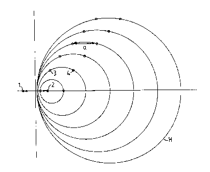
Fig. 1 is a view showing a field of a twin conductor:
Fig. 2 is a view showing a contact arrangement of a
second parallel twin conductor in the field distribution of the
first twin conductor;
Fig. 3 is an end view of a contact arrangement of a
4 x 2 connector; and
Fig. 4 is a diagrammatic representation for the
optimum angle.
DESCRIPTION OF THE PREFERRED EMBODIMENT
Referring to the drawings in particular, Fig. 1
represents the field distribution of a twin conductor 1, 2 with
the magnetic field lines H and the electric field lines E. The
magnetic crosstalk from the first twin conductor 1, 2 to the
second twin conductor 3, 4 is directly proportional to the
mutual inductance M of this arrangement. The mutual inductance
is yielded or determined by integrating the magnetic field
strength H of the twin conductor 1, 2 over the Area F3,4, which
is defined by the line conductor of the twin conductor 3, 4 as:
M =~of f H~z ~ x r Y . Z ) dF i
Fs,a
3

CA 02222635 2000-OS-10
it being the case that only the components of the magnetic field
strength H which are perpendicular to the surface F3,q, make a
contribution to this scalar vector product. The surface
integral represents the magnetic flux which passes through
between the two conductors 3, 4. This flux is equal to zero
when the two conductors 3, 4 are situated on a common magnetic
field line H. Influence charges which can flow off via the load
impedance, and thus generate crosstalk, are generated on the
conductors 3, 4 by the electric field E of the twin conductor
1, 2. The electric field E of the twin conductor 1, 2 generates
between the two conductors 3, 4 a potential difference of:
Conductor4
Vq - V3 = J Edr.
1 5 Conductor3
This is a line integral on an electric field line E
from conductor 3 to conductor 4, the potential difference being
zero when the electric field strength E is incident
perpendicular to the area F3,q defined by the conductors 3, 4.
The vector electric field E can also be described by the scalar
potential, the potential lines extending perpendicular to the
electric field lines E. For the case of electric decoupling,
it is then necessary for the two conductors 3,4 to be arranged
on an equipotential surface of the electric potential. Since
the electric and magnetic field lines E and H are perpendicular
to one another, the profile of the potential lines is identical
to the profile of the magnetic field lines H. This means, in
turn, that in the case of line conductors an arrangement with
magnetic decoupling also has electric decoupling. Because of
the finite extent of the conductors, the electric field E is
distorted near the conductor, since the surface constitutes an
equipotential surface. However, these deviations are negligible
in the case of larger spacings.
The magnetic field H of the twin conductor 1,2 is
represented in Fig. 3, the contact spacing of the conductors 1, 2
being "a". Possible arrangements of the second twin conductor
4

CA 02222635 2000-OS-10
3,4, for which the contact spacing is likewise "a", are
illustrated in Fig. 3. There is thus an infinite number of
possible arrangements of the twin conductors, 3,4, in which the
area F3,4 defined by the conductors 3,4 is parallel to the area
Fl,z, and spacing of the contact pairs 1,2 and 3,4 is the same
size in each case. Since the twin conductor 3,4 is located on
a magnetic field line H, the two twin conductors 1, 2 and 3, 4 are
decoupled both electrically and magnetically.
A contact arrangement for a 4 x 2 connector is
represented in Figure 3. The spacing of the conductors of each
twin conductor 1,2 and 3,4 and 5,6 and 7,8 is "a" in each case.
In addition, the forward conductors 1,3,5,7 and the return
conductors 2,4,6,8 lie in one plane in each case, the spacing
from a return conductor 2,4,6 to the respective neighbouring
forward conductor 3,5,7 likewise being "a". The angle a
resulting therefrom can be calculated by calculating with the
aid of Figure 4 as follows:
The forward conductor 3 describes, around the return
conductor 2 as a function of the angle a = 90°+(3, a circle of
radius 2A = a and a center displacement A. The circle equation
for this circle K1 is:
(X - A)2 + Yz - (2 A)z.
Complete decoupling requires the conductors 3, 4 to lie
on a magnetic field line which is described by a circle K2 of
radius RZ - M2 - AZ and a center point M:
(X - M) 2 + Y2 = Mz - A2 .
The point of intersection of the two circles K1, K2
is obtained by solving the system of equations:
(X - A) 2 - (X - M) 2 = (2A) 2 - N~ + A2 ~ X = 2 . A2
M - A
5

CA 02222635 2000-OS-10
It follows from Fig. 4 that for the center M = X+A,
resulting in the following relationship for the X-coordinate of
conductor 3:
x = ~2iA.
The angle ~i can be calculated from the X-coordinate
of conductor 3 as:
sin(3 = X - A = ~2 - 1 ~ ~3 = 11.95°
2 ~ A 2
This produces the desired angle a = (3+90° at 101.95°.
In the arrangement in accordance with Fig. 3, the twin
conductors 5, 6 and 7, 8 are no longer exactly on a magnetic field
line of the twin conductor 1,2, with the result that crosstalk
is induced. However, because of the large spacing this
crosstalk is very slight. It is possible using the same
principle in accordance with Fig. 3 to construct a multi-core
cable, for example a ribbon cable, in which the neighbouring
conductor pairs are arranged on an electric equipotential line
of a conductor pair based on connection means for connecting
said conductor pairs to form the cable. The connection means
may be plastic, rubber or other synthetic or natural material
used for forming a cable and defining the relative position
between conductors.
6

Representative Drawing
A single figure which represents the drawing illustrating the invention.
Administrative Status

2024-08-01:As part of the Next Generation Patents (NGP) transition, the Canadian Patents Database (CPD) now contains a more detailed Event History, which replicates the Event Log of our new back-office solution.

Please note that "Inactive:" events refers to events no longer in use in our new back-office solution.

For a clearer understanding of the status of the application/patent presented on this page, the site Disclaimer , as well as the definitions for Patent , Event History , Maintenance Fee  and Payment History  should be consulted.

Event History

Description Date
Time Limit for Reversal Expired 2011-11-28
Letter Sent 2010-11-29
Letter Sent 2010-03-22
Inactive: IPC from MCD 2006-03-12
Inactive: Reversal of will be deemed expired status 2006-02-17
Letter Sent 2005-11-28
Grant by Issuance 2002-08-20
Inactive: Cover page published 2002-08-19
Pre-grant 2002-05-31
Inactive: Final fee received 2002-05-31
Notice of Allowance is Issued 2001-12-05
Letter Sent 2001-12-05
Notice of Allowance is Issued 2001-12-05
Inactive: Approved for allowance (AFA) 2001-11-22
Letter Sent 2000-06-13
Inactive: Multiple transfers 2000-05-16
Amendment Received - Voluntary Amendment 2000-05-10
Amendment Received - Voluntary Amendment 2000-03-07
Letter Sent 2000-02-29
Request for Examination Requirements Determined Compliant 2000-02-15
All Requirements for Examination Determined Compliant 2000-02-15
Request for Examination Received 2000-02-15
Application Published (Open to Public Inspection) 1998-06-10
Inactive: First IPC assigned 1998-03-12
Classification Modified 1998-03-12
Inactive: IPC assigned 1998-03-12
Inactive: Filing certificate - No RFE (English) 1998-02-23
Filing Requirements Determined Compliant 1998-02-23
Letter Sent 1998-02-23
Application Received - Regular National 1998-02-20

Abandonment History

There is no abandonment history.

Maintenance Fee

The last payment was received on 2001-11-19

Note : If the full payment has not been received on or before the date indicated, a further fee may be required which may be one of the following

  • the reinstatement fee;
  • the late payment fee; or
  • additional fee to reverse deemed expiry.

Please refer to the CIPO Patent Fees web page to see all current fee amounts.

Owners on Record

Note: Records showing the ownership history in alphabetical order.

Current Owners on Record
KRONE GMBH
Past Owners on Record
MICHAEL GWIAZDOWSKI
Past Owners that do not appear in the "Owners on Record" listing will appear in other documentation within the application.
Documents

To view selected files, please enter reCAPTCHA code :


To view images, click a link in the Document Description column. To download the documents, select one or more checkboxes in the first column and then click the "Download Selected in PDF format (Zip Archive)" or the "Download Selected as Single PDF" button.

List of published and non-published patent-specific documents on the CPD .

If you have any difficulty accessing content, you can call the Client Service Centre at 1-866-997-1936 or send them an e-mail at CIPO Client Service Centre.


Document
Description 
Date
(yyyy-mm-dd) 
Number of pages   Size of Image (KB) 
Cover Page 1998-06-15 1 40
Cover Page 2002-07-16 1 35
Description 2000-05-10 6 290
Abstract 2000-05-10 1 13
Claims 2000-05-10 4 165
Representative drawing 1998-06-15 1 6
Description 1997-11-27 6 231
Drawings 1997-11-27 2 28
Abstract 1997-11-27 1 11
Claims 1997-11-27 1 28
Representative drawing 2002-07-16 1 8
Courtesy - Certificate of registration (related document(s)) 1998-02-23 1 118
Filing Certificate (English) 1998-02-23 1 165
Reminder of maintenance fee due 1999-07-28 1 114
Acknowledgement of Request for Examination 2000-02-29 1 180
Commissioner's Notice - Application Found Allowable 2001-12-05 1 166
Maintenance Fee Notice 2011-01-10 1 171
Fees 2002-11-20 1 38
Fees 1999-11-18 1 45
Fees 2001-11-19 1 43
Correspondence 2002-05-31 1 25
Fees 2000-11-17 1 42
Correspondence 2010-03-22 1 12
Fees 2009-11-18 2 124