Note: Descriptions are shown in the official language in which they were submitted.
CA 02222800 1997-11-28
WO 97/36656 PCTICA971~0209
R~R~ ~y~, ~.t FOR IN - T.TN~ RnT.T.~ R~E
FI~T~n QF ~ lNV ~:r- lQN
The present invention relates to a brake system for use on an
in-line roller skate. The brake system is activated by a pivotal
movement of the cuff and it is characterised by the ability to
move by translation or sliding movement relatively to the cuff
during the delivery of a braking movement.
l~ACRGROYND OF ~ ll!lV ~:r lON
Brake systems for use with roller-skates, particularly the
in-line category of skates fall in two different classes. The
first class relates to static pads that are mounted either at the
front or at the rear of the skate. To reduce his speed of travel
or stop altogether, the user is required to incline the skate for
engaging the brake pad with the ground surface. This approach to
brake design has several drawbacks. Perhaps, the most serious
disadvantage is the requirement for the user to orient the skate
at an angle with relation to the ground plane to provide breaking
action. At low speeds, this manoeuvre can be executed easily and
well even by novice users. At high speeds, however, precisely
where braking authority is critical, this manoeuvre can induce a
loss of balance with the potential of serious falls.
Another disadvantage of static brake pads is the poor
efficiency in terms of energy dissipation. For instance, when the
skate is angled to produce engagement between the brake and the
ground surface only a small fraction of the body weight rests over
the interface brake pad/ground. As a result, the rate of speed
reduction is often inadequate.
The second class of brake systems covers structures that
produce braking action as a result of movement of body parts,
~ 35 such as the leg or a hand, while maintaining all the skate wheels
firmly on the ground surface. There is generally a consensus in
the industry that such brake systems are easier to operate,
particularly for novice users, and are also safer.
SUBST TUTE SHEET lRULE 26)
CA 02222800 1997-11-28
WO 97/36656 PCT/CA97/00209
An example of a brake system using the movement of the leg to
operate the brake is disclosed in the U.S. patent 5,465,984. The
roller-skate described in this reference includes a boot mounted
on a frame that supports four wheels arranged in a common plane.
The boot includes a lower section, commonly called "shell" that
receives the foot of the user. The lower portion of the user's leg
is supported by an encircling cuff that is pivotally connected to
the shell about a generally horizontal axis. This pivotal
connection enables the cuff to follow the movement o~ the leg when
the leg is inclined forwardly or rearwardly during the skating
movement. The brake system is operated by a movement of the cuff.
When the cuff is tilted back, which occurs when the user brings
forward one foot (the one equipped with the brake) with relation
to the other foot, a brake pad is caused to engage the ground
surface.
The linkage that enables the transmission of the braking
movement from the cuff to the brake pad includes two components.
The first component is an arm pivotally connected to a rear
portion of the skate frame. The extremity of the arm that is
remote from the pivot axis carries the brake pad. The second
component is a rod-like actuator that connects the pivotal arm to
the cuff. The connections between the rod-like actuator, the brake
arm and the cuff are pivot joints as well. In essence, the
assembly behaves as a four link structure that causes the brake
arm to move down as the cuff is tilted back and to move up when
the cuff is tilted forward.
One major drawback of this brake system is its complexity and
high cost of manufacture. This is due primarily to the requirement
of using four pivot joints to operate the brake. Every such joint
in the final product increases significantly the cost of
manufacture because more complex components are necessary and the
assembly of such components requires more time on the production
line, more sophisticated automated assembly e~uipment and better
trained operators. In addition to those factors, other
expenditures must also be taken in consideration such as longer
development times and prototype testing to ensure that all pivot
SllBSTlTUTE SHEEr (RULE 26)
CA 02222800 1997-11-28
W097/36656 PCT/CA97/00209
points are structurally sound and will perform ade~uately over the
life of the product.
It has also been observed that roller-skates with brake
systems of the type disclosed in U.S. patent 5, 465, 984 are
relatively fragile and subject to premature failure in use. One
~ element that may explain the reason for this condition is the
orientation of the rod-like actuator. This component is located at
the rear of the skate, at a certain distance from the heel cup. In
this position, the rod-like actuator is sub~ect to accidental
impacts, particularly if the skate is used for playing a game
known as "Roller hockey". In a roller hockey environment, the
probability that the rod-like member is hit by a hockey stick or
a flying puck is high. Such impacts are sufficiently violent to
fracture the rod-like actuator with the effect that brake no
longer functions appropriately.
O~J~CT OF ~u~ l..v~ ON
An object of the present invention is to provide a brake
system for the roller skate that is of simple construction, yet
efficient for rapidly slowing or stopping the motion of the
skater.
As embodied and broadly described herein, the invention
provides a roller skate usable on a rolling surface, comprising:
an elongated frame;
a plurality of wheels rotatably mounted to said frame, said
wheels being arranged in tandem and lying in a
substantially common plane;
a footwear element mounted to said frame for receiving a foot
of a skater, said footwear element, including:
a shell portion for receiving a foot of the skater, said
~ shell portion including a heel cup for receiving a heel
of the skater's foot and a toe portion for receiving
~ 35 toes of the skater's foot, said heel cup including a
rear end defining a rear extremity of said shell
portion, said toe portion including a front end defining
a front extremity of said shell portion;
SUBSTITUTE SHEEr (RULE 2~
CA 02222800 1997-11-28
W O 97/36656 PCT/CA97/00209
an upper cuff portion retained to said shell portion, said
upper cuff portion being capable of at least partially
encircling a lower leg of the skater, said cuff being
capable of forward and backward movement with relation
to said shell portion in a direction generally parallel
to a longitudinal axis of said skate, said upper cuff
further including an abutment element mounted on a rear
portion of said cuff;
a brake system mounted to said skate, said brake system
including:
a brake arm pivotally mounted to said skate about a
pivot axis that extends generally transversally to
said skate, said pivot axis being located at a site
intermediate said front and rear extremities of
said shell portion;
a brake pad mounted to said brake arm at a location
remote from said pivot axis;
a brake actuation lever, including:
an abutment facing a rear portion of said cuff and
capable of engaging said abutment element;
first and second legs structurally connected to
said abutment, each of said first and second
legs including a forwardly extending portion,
said portion terminating at a location forward
of said rear extremity of said shell, each said
first and second legs being mounted to said
brake ar~ at a site inteL~ te said brake pad
and said pivot axis, whereby rearward rotation
of said cuff causes said abutment element on
said cuff to apply downward force on said
abutment on said brake actuation lever for
pivoting said brake arm by the intermediary of
said brake actuation lever in a direction to
produce engagement between said brake pad and
the rolling surface.
As embodied and broadly described herein, the invention
provides a roller skate usable on a rolling surface, comprising:
an elongated frame;
SUB~TITUTE SHEET (RULE 26)
CA 02222800 1997-11-28
WO 97/36656 PCT/CA97/00209
a plurality of wheels rotatably mounted to said frame, said
wheels being arranged in tandem and lying in a
substantially common plane;
a footwear element mounted to said frame for receiving a foot
~ of a skater, said footwear element, including:
a shell portion for receiving a foot of the skater, said
shell portion including a heel cup for receiving a heel
of the skater's foot and a toe portion for receiving
toes of the skater's foot, said heel cup including a
rear end defining a rear extremity of said shell
portion, said toe portion including a front end defining
a front extremity of said shell portion;
an upper cuff portion retained to said shell portion, said
lower cuff portion being capable of at least partially
encircling a lower leg of the skater, said cuff being
capable of forward and backward movement with relation
to said shell portion in a direction generally parallel
to a longitudinal axis of said skate,
a brake system mounted to said skate, said brake system
including:
a brake pad capable of engaging the rolling surface;
a brake actuation lever facing a rear portion of said
cuff, said brake actuation lever being coupled to
said brake pad;
a resilient tongue element projecting rearwardly and
downwardly from said cuff, said tongue and said
cuff defining a channel therebetween;
said brake actuation lever being slidingly received in
said channel;
an abutment element located at an upper end portion of said
channel, whereby rearward movement of said cuff causes
said brake actuation lever to slide in said channel and
engage said abutment element.
As embodied and broadly described herein, the invention
provides a roller skate usable on a rolling surface, comprising:
an elongated frame;
SUBSTITUTE SHEET tRULE 26
CA 02222800 1997-11-28
W 097/36656 PCT/CA97/00209
a plurality of wheels rotatably mounted to said frame, said
wheels being arranged in tandem and lying in a
substantially common plane;
a footwear element mounted to said frame for receiving a foot
of a skater, said footwear element, including:
a shell portion for receiving a foot of the skater, said
shell portion including a heel cup for receiving a heel
of the skater's foot and a toe portion for receiving
toes of the skater's foot, said heel cup including a
rear end defining a rear extremity of said shell
portion, said toe portion including a front end defining
a front extremity of said shell portion;
an upper cuff portion retained to said shell portion, said
lower cuff portion being capable of at least partially
encircling a lower leg of the skater, said cuff being
capable of forward and backward movement with relation
to said shell portion in a direction generally parallel
to a longit~ l axis of said skate,
a brake system mounted to said skate, said brake system
including:
a brake pad capable of engaging the rolling surface;
a brake actuation lever facing a rear portion of said
cuff, said brake actuation lever being coupled to
said brake pad;
a coupling between said actuation lever and said cuff,
said coupling including a slot member and a
projection member, one of said members being
mounted to said actuation lever and the other of
said members being mounted to said cuff, whereby
during movement of cuff said pro~ection member is
displaced in said slot;
said slot having a predetermined length defining a range
of movement of said projection therein;
- said slot having an end wall capable of engaging said
projection, whereby preventing further relative
movement between said brake actuation lever and
said cuff.
SUBSmUTE SHEET (RULE 26)
-
CA 02222800 1997-11-28
W O 97/36656 PCT/CA97/00209
As embodied and broadly described herein, the invention
provides a roller skate usable on a rolling surface, comprising:
an elongated frame;
a plurality of wheels rotatably mounted to said frame, said
wheels being arranged in tandem and lying in a
substantially common plane;
a footwear element mounted to said frame for receiving a foot
of a skater, said footwear element, including:
a shell portion for receiving a foot of the skater, said
shell portion including a heel cup for receiving a heel
of the skater's foot and a toe portion for receiving
toes of the skater's foot, said heel cup including a
rear end defining a rear extremity of said shell
portion, said toe portion including a front end defining
a front extremity of said shell portion;
an upper cuff portion retained to said shell portion, said
upper cuff portion being capable of at least partially
encircling a lower leg of the skater, said cuff being
capable of forward and backward movement with relation
to said shell portion in a direction generally parallel
to a longitll~in~l axis of said skate;
a brake system mounted to said skate, said brake system
including:
a brake arm pivotally mounted to said skate about a pivot
axis that extends generally transversally to said skate;
a brake pad mounted to said brake arm at a location remote
from said pivot axis;
an abutment element formed on a lower portion of said cuff
near a lower peripheral edge of said cuff;
said abutment element being capable of engaging through
either one of a rolling and sliding contact said brake
arm, whereby movement of said cuff induces downward
rotation of said brake arm to bring said brake pad in
- contact with the rolling surface.
As embodied and broadly described herein, the invention
provides a roller skate usable on a rolling surface, comprising:
SUBST TUTE SHFEr ~RULE 2B)
CA 02222800 1997-11-28
W O 97/36656 PCT/CA97/002~9
an elongated frame;
a plurality of wheels rotatably mounted to said frame, said
wheels being arranged in tandem and lying in a
substantially common plane;
a footwear element mounted to said frame for receiving a foot
of a skater, said footwear element, including:
a shell portion for receiving a foot of the skater, said
shell portion including a heel cup for receiving a heel
of the skater's foot and a toe portion for receiving
toes of the skater's foot, said heel cup including a
rear end defining a rear extremity of said shell
portion, said toe portion including a front end defining
a front extremity of said shell portion;
an upper cuff portion retained to said shell portion, said
upper cuff portion being capable of at least partially
encircling a lower leg of the skater, said cuff being
capable of forward and backward movement with relation
to said shell portion in a direction generally parallel
to a longitudinal axis of said skate;
a brake system mounted to said skate, said brake system
including:
a brake arm pivotally mounted to said skate about a
pivot axis that extends generally transversally to
said skate;
a brake pad mounted to said brake arm at a location
remote from said pivot axis;
an abutment mounted to said;
said abutment element being capable of engaging through
either one of a rolling and sliding con~act said
brake arm, whereby movement of said cuff induces
downward rotation of said brake arm to bring said
brake pad in contact with the rolling surface.
As embodied and broadly described herein, the invention
provides a roller skate usable on a rolling surface, comprising:
an elongated frame;
SUBSTITUTE SHEET (RULE 26
CA 02222800 1997-11-28
W O 97/36656 PCT/CA97/00209
a plurality of wheels rotatably mounted to said frame, said
wheels being arranged in tandem and lying in a
substantially common plane;
a footwear element mounted to said frame for receiving a foot
~ of a skater, said footwear element, including:
a shell portion for receiving a foot of the skater, said
- shell portion including a heel cup for receiving a heel
of the skater's foot and a toe portion for receiving
toes of the skater's foot, said heel cup including a
rear end defining a rear extremity of said shell
portion, said toe portion including a front end defining
a front extremity of said shell portion;
an upper cuff portion retained to said shell portion, said
lower cuff portion being capable of at least partially
encircling a lower leg of the skater, said cuff being
capable of forward and backward movement with relation
to said shell portion in a direction generally parallel
to a longitudinal axis of said skate, said upper cuff
further including an abutment element mounted on a rear
portion of said cuff;
a brake system mounted to said skate, said brake system
including:
a brake arm pivotally mounted to said skate about a
pivot axis that extends generally transversally to
said skate;
a brake pad mounted to said brake arm at a location
remote from said pivot axis, angular movement of
said brake arm causes engagement of said brake pad
with the rolling surface;
a resilient element between said brake arm and said
frame, said resilient element being in a condition
of resilient deformation when said brake pad
- engages the rolling surface, in said condition of
resilient deformation said resilient element urging
~ said brake arm toward a position in which said
brake pad is out of contact with the rolling
surface.
SUBSmUTE S~EET (RIJLE 26
CA 02222800 1997-11-28
W 097/36656 PCT/CA97/00209
As embodied and broadly described herein, the invention
provides a roller skate usable on a rolling surface, comprising:
an elongated frame;
a plurality of wheels rotatably mounted to said frame, said
wheels being arranged in tandem, said wheels are capable
of rotating in said frame about respective axes that lie
in a common horizontal plane;
a footwear element mounted to said frame for receiving a foot
of a skater, said footwear element, including:
a shell portion for receiving a foot of the skater, said
shell portion including a heel cup for receiving a heel
of the skater's foot and a toe portion for receiving
toes of the skater's foot, said heel cup including a
rear end defining a rear extremity of said shell
portion, said toe portion including a front end defining
a front extremity of said shell portion;
an upper cuff portion retained to said shell portion, said
upper cuff portion being capable of at least partially
encircling a lower leg of the skater, said cuff being
capable of forward and backward movement with relation
to said shell portion in a direction generally parallel
to a longitudinal axis of said skate;
a brake system mounted to said skate, said brake system
including:
a brake arm pivotally mounted to said skate about a
pivot axis that extends generally transversally to
said skate, said pivot axis being located at a site
intermediate said front and rear extremities of
said shell portion, said pivot axis being located
above said common horizontal plane;
a brake pad mounted to said brake arm at a location
remote from said pivot axis.
_ As embodied and broadly described herein, the invention
provides a brake assembly suitable for use in a roller skate, the
assembly comprising:
SUBSTITUTE SHEEl- (RUEE 26)
CA 02222800 1997-11-28
WO 97/36656 PCT/CA97/00209
11
~A) a first member capable of being secured to an end
of the roller skate, said first member having a plurality of
walls, the walls defining a channel thereinbetween;
(B) a second member capable of being received within the
~ channel defined by the walls of said first member;
5(C) means for selectively positioning said second member
- within the channel defined by the walls of said first member;
and
(D) a brake pad secured to said second member;
whereby a change in the position of said second member within
10said first member will cause a change in the relative
position of said brake pad with respect to a skating surface.
As embodied and broadly described herein, the invention
provides a brake system for a roller skate comprising:
15a brake pad made of high friction material for engaging a
rolling surface on which the roller skate is displaced:
a support element to which said brake pad is mounted;
a vibration absorbing body mounted between said brake pad and
said support element, said vibration absorbing body
20being made of material more compressible than said brake
pad.
DEscRIPTION OF ~u~ DR~WINGS
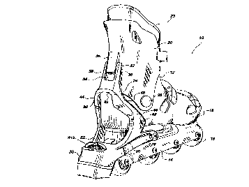
Figure 1 is a prospective view ~rom the rear of an in-line
roller skate with a brake system constructed in accordance with
the present invention;
30Figure 2 illustrates a roller skate with a brake system in
accordance with a variant;
Figure 2a is a variant of the embodiment shown in Figure 2;
35Figure 3 is a side elevational view of a roller skate with a
brake system in accordance with a further variant;
S~ UTE SHEET(RULE 263
CA 02222800 1997-11-28
W O 97/36656 PCT/CA97/00209 12
Figure 4 is a fragmentary enlarged view of the lower edge
portion of the cuff that activates the brake system of the skate;
~ igure 5 is a side elevational view of the brake pad assembly
in accordance with the present invention;
Figure 6 is a perspective view of an inner casing of the
brake pad assembly shown in figure 5;
Figure 7 is a fragmentary top plan view of the inner casing
shown in figure 6;
Figure 8 is a side elevational view of the inner casing shown
in figure 6;
Figure 9 is a fragmentary vertical cross-sectional view of
the inner casing shown in figure 6;
Figure 10 is the side elevational view of a brake pad
component;
Figure 11 is a front elevational view of the brake pad
component depicted in figure 10;
Figure 12 is a top plan view of an insert for locking the
brake pad component and also for providing vibration dampening;
and
Figure 13 is a side elevational view of yet another
embodiment of a roller skate ~raking system in accordance with the
invention.
DESCRIPTION OF PREFERRED EMBODIMENTS
With reference to the annexed drawings, more particularly to
figure 1, the present invention provides an improved brake system
for use with in-line roller skates. The roller skate designated
comprehensively by the reference numeral 10 includes a boot 12
- SUBSTITUTE SHEET (RULE 26~
CA 02222800 1997-11-28
WO 97/36656 PCTICA97/00209
~ 13
mounted on a frame that carries a plurality of wheels 16 arranged
in a common vertical plane that contains the center line of the
skate. The boot 12 includes a shell 18 that encloses the foot of
the user. A cuff 18 encircles the lower leg to provide lateral
- stability. The cuff is pivotally connected to the shell 18 at two
sites located on either side of the skate. Only one such site is
shown in the drawings and it is identified by the reference
numeral 22. This structure allows the cuff to pivot forwardly or
rearwardly, thus accommodating the movements of the lower leg
during skating, while maintaining the leg in the plane that
contains the frame 14 and the wheels 16.
The shell 18 and the cuff 20 are made of plastic material by
injection moulding. The material used should be sufficiently
flexible to provide good comfort potential while being abrasion
and impact resistant to protect the foot.
Most preferably, a liner is mounted in the boot 12 to provide
a high degree of comfort while maintaining the foot stable in the
shell 18 and the cuff 20. The liner can be made from a variety of
different materials. The material of choice should be soft and
highly resilient to conform to the surface of the foot, thus avoid
pressure points that could result in discomfort. Normally, the
liner would extend from the toe portion of the shell 18 up to the
upper end of the cuff 20. The liner can be made as a single piece,
or as two or more separate elements ~oined in the ankle region of
the foot.
The roller skate 10 features a novel brake system designated
by the reference numeral 24. The brake system is mounted at the
rear of the skate and includes two main components namely, an
actuation lever 26 and a brake arm 28 that carries a brake pad
assembly 30. The actuation lever 26 is designed to interact with
the cuff 18 to urge the brake arm 28 down when the cuff 18 is
pivoted rearwardly for, in turn, bringing the brake pad assembly
30 against the ground surface. The actuation lever 26 includes an
upwardly ext~n~;ng component 32 provided with a longitudinally
extending centrally located groove 34 that slidingly receives a
tongue 36 integrally formed with the cuff 20. The tongue extends
SUBSmUTE SHEEJ (RULE 26)
CA 02222800 l997-ll-28
W097/36656 PCT/CA97/00209
14
rearwardly and downwardly defining a channel with the cuff. The
upper end of the actuation lever on which the groove 34 is ~ormed
is slidingly received in the channel. On each side of the groove
34 extends guides 38 that hold the tongue 36 captive. As such, the
upstanding member 32 can only slide longitudinally in the cavity
formed between the tongue and the rear surface of the cuff and no
lateral movement is authorised between the tongue 36 and the
upstanding member 32. The upstanding member 32 connects at the
base with a fork-like structure 42 that joins the brake arm 28.
The fork-like structure 42 includes a pair of legs 44 in a spaced
apart relationship, extending on either side(the medial and
lateral sides) of the heel cup of the skate. Each leg 44 includes
an upper forwardly extending segment 46 that connects with a lower
rearwardly extending segment 48. The segments 46 and 48 define
between them an angle of approximately 45 degrees. The lower end
of the segment 48 joins with the brake arm 28.
The brake arm 28 is a fork-like structure including a pair of
angled sections(bifurcations) 50 and 52 that join with one another
at a convergence located at the rear extremity of the brake arm 2 8
where the brake pad assembly 30 is located. The sections 50 and 52
extend along diverging directions to define between them a space
for a~. -dating the rear section of the skate frame. The forward
extremities of the sections 50 and 52 are pivotally connected to
the frame 14 to enable the entire brake system 2 4 to pivot up and
down with relation to the skate about a pivot axis that is
parallel to the pivot axis the cuff 18. The pivot axis of the
brake arm is located above the horizontal plane that contains the
axles of the wheels, and below the sole of the shell and the pivot
axis of the cuff.
The brake system 24 operates as follows. To activate the
system the user is required to effect a rearward rotation of the
cuff. In practice, this can be accomplished by bringing forward
the foot equipped with the brake for causing the leg and the cuff
18 to tilt back. The rearward pivoting of the cuff 18 causes the
tongue 36 to slide down in the groove 3 4 of the upstanding member
32. This sliding movement continues until the upper edge of the
upstanding member 32 abuts against the base of the tongue 36 that
SUBSTITUTE SHEET (RU~E 26)
CA 02222800 1997-11-28
W O 97/36656 PCTICA97/00209
constitutes an abutment. At this point, the brake system 24
descends until the brake pad assembly 30 engages the ground
surface. It will be noted that during this movement the tongue 36
and the upstanding member 32 move along different trajectories
because they pivot about horizontal axes that are vertically
spaced apart. As such, a certain flexibility is necessary in the
connection tongue 36/upstanding member 32 to accommodate this
movement. The tongue 36 is dimensioned to provide a sufficient
level of flexibility in order to yield away from the cuff 18
during the progressive descent of the combination cuff/brake
system.
This brake system is particularly advantageous over the prior
art designs in terms of simplicity, durability, ease of assembly
and cost of manufacture. Indeed, the brake system uses a single
pivot joint rather than multiple joints, as suggested by the prior
art. The structure is thus more robust and unlikely to fail even
after years of service. It is very easy to assemble to the skate.
More specifically, the brake system can be conveniently formed as
a single unit (with the exception of the brake pad assembly 30)
and connected to the skate simply by inserting the upstanding
member 32 under the tongue 36 and then install screws at the
pivots at the extremities of sections 50 and 52 of the brake arm.
The orientation of the legs 44 that connect with the
upst~n~;ng member 32 constitutes another advantage. Since the legs
extend on either side of the heel cup they are less susceptible to
accidental impacts that may damage them. Actually, the heel cup
acts as a guard protecting the legs 44 against blows to the skate
that may be encountered in a game of roller hockey, for example.
The angular relationship between the sections 46 and 48 of
the legs 44 and 46 has been found advantageous in that it provides
- a noticeable degree of vibration dampening when the brake pad
assembly 30 engages the ground surface. More specifically, the
r 35 sections 46 and 44 are capable to flex within narrow limits at
their junction to absorb some of the vertical disturbances
transmitted by the brake pad assembly 30. The junction between the
sections 46 and 48 provides the primary dampening function.
SUBSTITUTE SHEET (RULE 26)
CA 02222800 1997-11-28
W O 97/36656 PCT/CA97/00209 16
Additional dampening also occurs at the juncture between the
upstanding member 42 and the legs 44 and also at the base of the
legs 44 where they join with the brake arm 28. The vibration
dampening properties of these sites may be controlled by varying
several factors. For instance, the angle formed between the
components determines, among other elements, the degree of flex.
Another consideration is the rigidity of the material. In general,
the smaller the angle between the components and the softer the
material from which those components are made, the more pronounced
the flexing movement will be. It should be appreciated that
although a certain level of flexing movement is desirable to
provide vibration dampeni~g behaviour, excess flex may be
unsuitable for most applications as the structure of the brake
will have a tendency to distort during heavy braking effort.
The precise location where the legs 44 join with the brake
arm 28 has a significant impact on the dynamic behaviour of the
brake system. The distance between the pivot axis of the brake arm
28 and the location where the legs 44 join with the brake arm
determines on one hand the leverage (m~h~nical advantage) acting
on the brake arm 28, and on the other hand the rate of descend of
the brake pad assembly 30 for a certain amount of angular
displacement of the cuff 18. More specifically, the closer the
legs 44 and 46 lie with respect to the pivot axis of the brake arm
28, the faster the brake pad 30 will move toward the ground when
the cuff 18 is pivoted rearwardly. On the down side, less leverage
is available with the consequence that the user must press harder
on the cuff 18. Thus, by varying the location of the legs 44
relative the pivot axis of the brake arm 28, the manùfacturer can
fine-tune the skate for different applications. For example a more
aggressive brake setting, where the brake acts faster but requires
a higher effort could be preferred by professionals, while a more
moderate setting could be better suited for novice skaters.
To disengage the brake pad assembly 30 from the ground
surface the user must pivot forwardly the cuff 18. The engagement
between the tongue 34 and the upstanding member 32 causes the
brake assembly to be pivoted upwardly along with the cuff 18. It
will be apprecia~ed that the tongue 36, while the brake is applied
SUBSTITUTE S~IELT (RUL~ 26)
CA 02222800 1997-11-28
WO 97/36656 PCT/CA97/00209
17
is in a condition of resilient deformation, the portion of the
tongue that is remote from its base yielding away from the cuff.
This resilient deformation is caused by the pivotal movement of
the upst~n~;ng - h~r 32 toward the ground surface when the brake
is applied. The yielding tongue 36, attempting to recover its
original configuration presses on the upstanding member 32 which
has a tendency to induce in that upstanding member an upward
pivotal movement tending to disengage the brake pad 30 from the
ground surface. Moreover, the pressure applied by the tongue 36 on
the upst~n~;ng member 32 creates a significant level of friction
between these components so that when the cuff 18 is pivoted
forwardly the brake assembly is caused to follow. These two
combined effects are responsible for disengaging the brake pad 30
from the ground when the user tilts forwardly the cuff 18.
Figure 2 of the annexed drawings illustrates a variant of the
braking system in accordance with the invention. In this drawing
components similar or identical with the components of the skate
shown in ~igure 1 will be designated by the same reference
numerals followed by the suffix "A". The brake system 24a is
s;~;l~r to the previous embodiment with two exceptions. First, the
upstanding member 32a is no longer connected to the cuff 18a. The
upstanding member 32a includes an upper extremity 100 that is
engaged by a projection 102 extending from the cuff 18a, when the
cuff is tilted back. Thus, the projection 102 merely acts as an
abutment to press the brake system 24a down and has no effect in
raising the brake pad assembly 30a from the ground surface. It
will be noted that as in the case of the previous embodiment the
projection 102 and the extremity 100 of the upst~n~;ng member 32a
move along different trajectories during the rearward pivotal
motion of the cuff 18a. As a consequence, a relative displacement
occurs between the mating surfaces of the upstanding member 32 a
and the abutment 102. It is desirable to reduce, as much as
- possible, the amount of friction developed at this interface to
facilitate the delivery of the braking movement. As such, it could
be desirable to apply on the tip of the upstanding member 32a, the
abutting surface of the projection 102, or on both surfaces a low
friction substance such as Teflon (Trademark) or any other
suitable material known to the person skilled in the art.
SUBSTITUT~ S~JEET (RUEE 26~
CA 02222800 1997-11-28
W O 97/36656 PCT/CA97/00209 18
The other difference with the previously described embodiment
resides in the use of a resilient member whose function is to
raise the braking assembly 24a when the cuff 18a is pivoted
forwardly. In the most preferred embodiment the resilient member
is in the form of a strip 104 integrally moulded with the brake
assembly 24a and projecting to fit in a cavity in the rear end of
the frame 14a. As such, when the brake system 24a is pivoted down
the strip 104 that is held captive against the frame 14a is
resiliently distorted. When the cuff 18a is pivoted forwardly the
distorted strip returns to its original configuration and, as a
result, raises the brake system 24a above the ground surface.
Under a possible variant, a coil spring may be incorporated in the
pivot point connecting the brake system 24a to the skate in order
to accomplish a similar function.
Figure 2a illustrates a possible modification of the brake
system 24a that resides in the coupling brake actuation
lever/cuff. The upstanding member 32a is provided with an
elongated slot 33 in which is located a projection 35 formed
integrally with the cuff 18a. The lateral dimension of the
projection 35 is slightly less than the width of the slot 33 to
prevent the upst~n~;ng member from moving laterally. Thus, the
projection 35 acts as a lateral stabiliser allowing the UpstAn~; ng
member 33 only to move up and down during brake
application/release motions. To authorise such up/down movements
the projection 35 has a vertical dimension much less than the
length of the slot 33. It is the length of that slot which
determines the ~x;~um angular range of movement of the brake
system 24a. The value of this parameter can be changed to suit
different applications where a different angular motion range of
suitable.
Figure 3 illustrates a further variant of the roller skate in
accordance with the present invention. Components similar or
identical to those illustrated in figures l and 2 will be
designated by the statement reference numerals followed by the
suffix "B". The skate 10 b includes a braking system 24 b that is
activated by the lower edge portion of the cuff 18 b. More
SUBSTITUTE SHEFr tRULE 26)
CA 02222800 1997-11-28
W 097/36656 PCT/CAg7/00209
19
specifically, the braking system 24 b comprises a pair of legs 200
(only one leg being shown in the drawing) on either side of the
heel cup. The legs are connected to one another at their upper
extremities by a crosspiece 202 that is complementary to the shape
of the heel cup. Each juncture site defined between the lateral
extremities of the crosspiece 202 and the respective legs 200
includes a projecting tab portion 204 to which is mounted a roller
bearing 206. The bearing 206 is engaged by the lower edge portion
of the cuff 18 b so that when the cuff is tilted backwards the
brake assembly 24 b is caused to move down and to engage the
ground surface. An interesting feature of this embodiment is the
ability to control the rate of descend of the brake system 24 b in
accordance with the profile of the lower edge portion of the cuff
18 b. Figure 4 provides additional details on this point. The
lower edge portion 208 of the cuff 18 b is provided with two ramp
surfaces having different slopes on which the roller bearing 206
rides. The first ramp surface 210 has an aggressive profile (the
slope is significant) in order to provide a fast rate of descend
before the brake and assembly 30 b engages the ground surface.
Thus, it surfaces to impart to the cuff 18 b a small angular
displacement to cause the brake pad assembly 30 b to engage the
ground surface. After the roller bearing 206 has reached the end
portion of the aggressive ramp 210 it engages the second ramp 212
of more moderate slope designed to provide an increased leverage.
This feature enables to generate a significant pressure at the
interface brake pad assembly 30b/ground without the necessity of
heavy leg effort acting on the cuff. Moreover, the skater can
modulate the brakes better.
If desired, the ramp portion 212 includes near the end of
travel zone a notch 214 in which the roller bearing 206 can be
trapped. This enables to achieve a condition of contiguous brake
application without the necessity of pressing on the cuff 18b. To
disengage the brake the user needs to push forwardly on the cuff
18b with sufficient force to dislodge the roller bearing 206 from
the notch 214.
As is the case of the embodiment disclosed in figure 2, a
spring element is provided to urge the brake assembly 44 upwards.
SIJBSTITUTE S~lEEr (RULE 26)
CA 02222800 1997-11-28
W 097t36656 PCT/CA97/00209
This means that when the cuff 18 ~ is pivoted forwardly, the brake
assembly 24 b automatically raises itself.
Figures 5 to 12 illustrate the various components of the
brake pad assembly 30. It will be apparent from figure 5 that such
brake pad assembly can also be used for applications where the
brake pad is fixed relative the skate frame (braking is affected
by raising the toe portion o~ the skate to bring the brake pad in
contact with the ground surface). In such cases, minor
modifications are required to the structure of the brake pad
lo assembly to connect it to the skate frame, as it will be discussed
later.
The brake pad assembly 30 includes an outer casing 300
including a top wall 302, sidewalls 304 and a rear wall 306. An
opening 308 extending across the entire width of the casing 300 is
provided to receive an adjustment knob 312 that is used to adjust
the distance between the brake pad and the ground surface.
Typically, such adjustment is made to compensate for wear of the
brake pad.
The casing 300 is a hollow structure slidingly receiving
therein an inner casing 314 that carries the brake pad 316 made of
vulcanised rubber. The inner casing 314 includes a flat surface
318 provided with a long U-shAre~ slot 320. Below the top surface
318 is provided an internal flange 322 that is parallel to the top
surface 318 and includes its own U-shaped slot. Both U-shaped
slots register with one another and define between them a channel
324 for slidingly receiving a nut 326 in which is engaged a
threaded shank 328 of the adjustment knob 312. The lateral
~ ions of the channel 324 are selected to prevent the nut 326
~rom rotating. Thus, when the adjustment knob 312 is turned, the
threaded shank 328 is longitl~;n~lly displaced relative the entire
inner casing 314.
The opposing side walls of the inner casing 314 includes
three vertically extending parallel grooves 330 that are
horizontally spaced from one another to define between them
alignment ribs 332. The inner surface of the sidewalls 304 of the
SUBSTITUTE SHEEr (RULE 26~
CA 02222800 1997-11-28
WO 97/36656 PCT/CA97/00209
21
outer casing includes complementary sets of ribs and ~rooves
configured to slidingly engage the grooves 330 and the ribs 332.
This structure allows the inner casing 314 to vertically slide
within the outer casing 300 while remaining perfectly aligned
therewith.
The bottom wall of the inner casing 314 includes a large U-shaped
- slot 334 for slidingly receiving therein the brake pad 316. More
particularly, the brake pad 316 includes a T-shaped head 336
defined by a pair of diverging arms 338 and a narrow body 340. The
brake pad 316 is mounted to the inner casing 314 by inserting the
head 338 therein so the diverging arms 338 rest on top of the
bottom wall while the body 340 is received in the space defined by
the U-slot. To lock the brake pad 316 in place, a U-shaped insert
342 shown in figure 12 is placed on the narrow body 340. The
insert 342 is made of soft thermal plastic rubber which is
sufficiently compressible to create an interference fit and thus
prevent the brake pad 316 from easily sliding out of the inner
casing 314. The material of the insert is softer and more
compressible than the material of the brake pad. Neoprene
material has been used with success. Another advantage of the
insert 342 is its ability to absorb at least some of the
vibrations generated during the engagement brake pad 316/ground
surface. The ability of the insert 342 to filter out vibrations is
an interesting feature of the invention because it allows reducing
the level of harshness transmitted to the foot during braking.
If the user desires to vary the distance between the brake
pad 316 and the ground surface, to compensate for wear for
example, it suffices to turn the knob 312 to cause a longitudinal
displacement of the shank 328 relative to the nut 326. However,
since the knob 312 is locked against any transitional
displacement, the inner casing 314 is caused to slide (either in
or out depending upon the direction of the rotation) with relation
~ to the outer casing 300.
The embodiment of the brake pad assembly 30, as shown in
figure 3 has been designed for use as a static brake system. At
this end, the brake pad assembly is provided with a mounting
system comprised of arms 344 that connect on the axle of the
SUBSTITUTE SHEET (RULE 26)
-
CA 02222800 l997-ll-28
W 097/36656 PCT/CA~7/00209
22
rearmost wheel and an upper arm 346 fitted in a slot on the frame.
A bolt 348 secures the upper arm 346 in place.
Figure 13 illustrates yet another variant of a roller skate
braking system constructed in accordance with the present
invention. The skate 400 includes an articulated cuff 402 that is
capable of pivotal movement about an axis extending generally
transversely with relation to the longitudinal axis of the skate.
The cuff 402 includes an actuation lever 404 located near the
pivot point 406 connecting the cuff 402 to the shell of the skate.
10 The actuation lever 404 engages the brake arm 408 that is
pivotally connected at 410 to the frame of the skate. As in the
case with the previous embodiments, the pivotal axis of the brake
arm is generally parallel to the pivot axis of the cuff and it is
vertically spaced apart from it.
The rear extremity of the brake arm 408 includes a brake pad 412
that engages the ground when the brake arm is pivoted forwardly
under the influence of the cuff 402. The brake arm 408 includes a
flat bearing surface 414 that is parallel with a complementary
20 bearing surface 416 provided on the actuation lever 404. It will
be noted that the bearing surfaces 414 and 416 meet along an
interface plane that intercepts the pivot axis of the cuff 402
To activate the brake the user is required to tilt the cuff 402
25 backwards. As a result, the actuation lever 404 that is integrally
formed with the cuff 402 or made as a separate component but
rigidly secured thereto is caused to swing down. The actuation
lever 404 engages the brake arm 408 and causes the brake arm to
move down. Since the bearing surfaces 414 and 416 are located at
different distances from their respective pivot axes a sliding
movement occurs between those surfaces during the downward
movement of the brake arm 408~ It is desirable to reduce the level
of friction at this interface in order to facilitate the brake
delivery movement. Thus, low friction substances such as Teflon or
hard nylon can be used on one bearing surface on or both.
To return the brake arm 408 to be inoperative position (raise the
brake arm so the brake pad 412 is no longer in contact with the
- SUBSTlTUTe SI~EEl- ~RULE 26~
CA 02222800 1997-11-28
W 097136656 PCT/CA97/00209
23
ground) a return spring is required. Such spring may be in the
form of a tongue integrally formed with the brake arm 408 and
engaged in a slot formed on the frame. In a variant, the brake arm
408 can be provided with a coil return spring mounted at the pivot
~ 410.
It should be appreciated that the skate 400 includes a
actuation lever 404 and an associated bra~e arm 408 on each side,
the brake arms being ~oined by a cross-bar running below the heel
cup (not shown in the drawings).
SUBSTlT~lTF SHEET ~RULE 26)