Note: Descriptions are shown in the official language in which they were submitted.
CA 02223563 2000-09-19
61368-1101
1
IN-LINE COATING AND CURING A CONTINUOUSLY MOVING
WELDED TUBE WITH AN ORGANIC POLYMER
BACKGROUND OF THE INVENTION
This invention relates to in-line coating of a
continuously moving substrate, such as tube, pipe, or conduit,
of the type used for applications such as metal fencing, fire
protection piping, mechanical pipe or tubing, or electrical
conduit. More specifically, this invention relates to
galvanizing and overcoating of such substrates.
The art of forming, welding, and coating tubes and
pipes is an old art. Many manufacturing operations exist which
use techniques decades old. As an example, modern galvanizing
procedures have been described as the outdated inheritance of
original hot dip galvanizing in which cold articles were dipped
in heated zinc pots. See U.S. Patent No. 4,352,838 at column
1, lines 13-19.
While the art is old, significant advances have been
made by industry leaders. These advances include the advance
of PCT Publication No. WO 93/00453 published January 7, 1993,
the advance of U.S. Patent No. 5,364,661 issued Nov. 15, 1994,
and the advance of U.S. Patent No. 5,506,002 issued April 9,
1996. As reflected in these patents and publication,
galvanizing of continuous tubes and conduits has progressed to
the point of rapid speeds of the tubes and conduits to be
galvanized, on the order of six hundred feet per minute.
Galvanizing has also progressed through the elimination of
secondary or elevated zinc containers in favor of zinc pumped
through cross-tees, spray nozzles and drip nozzles. Zinc
CA 02223563 2000-09-19
61368-1101
2
application dwell times have been reduced to tenths of seconds,
and contact zones to inches.
Industry leaders have also advanced the application
of non-metal coatings, as well, as shown in U.S. Patent No.
5,453,302 issued September 26, 1995. As in this patent,
protective coatings are applied by vacuum coating apparatus.
Applications of coatings through alternate coating
technologies have also been disclosed. As shown in U.S. Patent
Nos. 3,559,280 issued Feb. 2, 1971, 3,616,983 issued Nov. 2,
1971, 4,344,381 issued Aug. 17, 1982 and 5,279,863 issued Jan.
18, 1994, electrostatic coating has been considered one
possibility. As disclosed in U.S. Patent No. 3,559,280,
electrostatic spray coating is accomplished after water spray,
sizing, straightening, and drying, and in the multiple steps
and locations of a spraying or coating section, a separate
following baking or hardening chamber, a separate following air
blower and a separate following water spray. As disclosed in
U.S. Patent No. 3,616,983, electrostatic powder coating is
accomplished as an alternative to other coating methods after
earlier application of liquid coatings, and after heating
applied by an external heater. As disclosed in U.S. Patent No.
4,344,381, electrostatic spray coating is accomplished in an
inert atmosphere by organic solvent-based, liquid coating
materials.
SU1~2ARY OF THE INVENTION
Despite the advances of the art, opportunity has
remained for invention in the
CA 02223563 2003-08-O1
61368-1101
application of coatings tc; zinc cJ,'>at.ed and once:>ated tubing.
The times and distances fc:r_ coatings to be applied and cured
have created at: le~~st i~. ~>art koarrif:~r.s t,o incrc.~ases in
speeds in the continuou:_; in-line r~;roducti~~n of tubing.
cwerspray, drippage. a:nd t.l-ae hike ~,.a~ue caused si_ibst:antially
incomplete usage of coat_.ing nat:er~ a.:l.s, and wastage.
Coatings have been incont;i atent~ ir~ t;hici~.ness arud c=overage,
and thicker than needed.
In szzmmary, tlueref're, the invention is both tube
products and improvemen;:s ire the methods o:f coritir~uous
production of coated tur,irrg. As most preferred, the tubing
and improved production a. r,c:lude he;t di.p ga1~Jan.zec~ zinc
coating of tubing, and ;.rrn;oediatel~,~ ,_3.fter solid~..fication of
the surface of the zinc: c~c~<ati.ng h~:as oc:c:urred, _i.n-line, clear
coating of the tubing with: crgania: r~ol ymer coa.t~ing. The
remaining latent heat o? t.-~e galv<lnizinq cure: or thermosets
the clear coating, and t:>wo::: c:7..E~ar ~::o,-.~t:.i.ruci pr~?se..rves a
consistency and shine, :>r reflectivity, c~f the zinc
previously unseen :..ru th::> t_i_ni_shed produc=t: of continuous z=inc
coating of tubing, i_n ttre range or chrome. In additional
embodiments, organic po_i yrner coat ~.nc~s az:~E: applied to zinc;
coated and unc~~~ate~ tub_i_rn:~, and tre orgarvic pa:.Lymer coatings
are applied by eleca.rcsi::~at~:.-_<: appl __c~rti.c:~ru c-t= powder. The
powder is uncharged as .i.t~ leaves _ts noza.les, and charged in
fields created by an ar ra:~;~ ef cha vgE:'d w ~r a gr.i.~~s . The
powder thermosets to coat:. t:r.e tubing in approhimately five
seconds, and coating :is curnp:'_et.ed w i_thc-~ut ~iqu id coating
materials, post: heat, ocv an~Y baking or W .rrdening chamber.
According to ~~:~e Gspect the invention provides in
a tube a product of the tvype comp:r_ising a metal base tube
with or without: a zinc :::pa ~ ing arn:~ ~~ri ~h an overlying coating
of organic polymer, the :i_rnprovement c.orr~p.r_ising said coating
CA 02223563 2003-08-O1
61368-1101
3a
of organic poly::ner comprising a truermosetting, cross-linking
polyester, said poiyestf~r being triglycidyl isc>cyanurate
(TGIC) polyester a~>pliec:l i.rrsnadiatel~,r cver_ the metal base
tube, without a primer, wherein trre tube product was formed
from a process includinc:~ applying the TGIC polyester as a
powder to the metal basE;> t ube dur7 nc~ tra.ve.Lling of_ the tube.
According to another aspect the invention provides
in a tube product of th~: t:ype, c:om~:~,rising a metal tube base
tube with a zinc coatin:~ and with an overlying coating of
organic polyme, tire im~~ro~rrerrient ~::ompz:isirzg an organic
polymer of a thermosett_,_r~c~, cross-linking polyester, said
polyester being triglycu..cayl i.socyanurate (TGIC;1 polyester
applied immediately over t:he metai_ base tube, without a
primer, said polymer' be_i.rLg clear, arzd wherein. at Least a
portion of said zinc co<~.t: i_ng, as ~~bserved through the clear
polymer coating, has thc~w~ .Leflectivity of chrome.
According to ~y~E~t: another aspect: the invention
provides in a process for producing a metal base tube with
or without a zinc coat:ivu<~ and with an c>~rerlyirng coating of
an organic polymer appl :i.ed over said rne tal base tube, an
improved proce:>s compri.s:Lng the st:ep cof applying said
organic polymer comprising a thermose~tir2g crc:~ss-linking
polyester, said pol.yestc=_z~ be:ing t:rigl_:ycidyl isocyanurate
(TGIC) polyester appl:iEd immediately over said metal base
tube, without a primer tua;ring been appliec:l to said metal
base tube, said applying step inc:hiding applying said
polymer as a powder to said metal base tube while said metal
base tube is t:rave~ll.:inc:l.
CA 02223563 1997-12-04
WO 96/40450 PCT/CTS96/09296
4
BRIEF DESCRIPTION OF TFIE DRAWING
The preferred embodiment of the invention will now be described with
reference to the accompanying drawing. The drawing consists of four figures,
as
follows:
Fig. 1 is a perspective view of the eduipment of practice of the preferred
embodiment ofthe invention in a tube production mill:
Fig. 2 is a second perspective of apparatus of the preferred embodiment,
namely a coater, broken away to reveal internal detail:
Fig. 3 is a schematic of the powder feeding_ apparatus of the preferred
embodiment; and
Fig. 4 is a flow diagram of the placement of the coating apparatus as most
preferred in the tube mill.
SUBSTITUTE SHEET (RULE 26)
CA 02223563 1997-12-04
WO 96/40450 PCT/US96/09296
' DETAILED DESCRIPTION OF THE PRESENT INVENTION
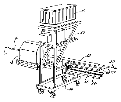
A preferred embodiment of the invention is practiced in a process and with
equipment as shown in Fig. 1. Tubing 10, previously fon~ted from strip steel
and
previously welded, moves into and through a coater 1? in the direction of
arrow 11.
5 Auxiliary equipment ofthe coater 10 is mounted on a moveable frame 14.
Powder for
coating the tubing 10 moves from a fluidized bed 16 through augers 18, 20,
into
nozzles not shown in Fig. 1 and is broadcast into the coater I 2. The powder
coats the
preheated tubing 10, which exits the coater 12 in the direction of arrow 22.
Refernng to Fig. 2, the coater 12 houses an array 24 of charged electrical
wires
which establish an electrostatic field or fields about the tubing 10 passing
through the
coater 12. The nozzles not shown in Fig. 1 are nozzles 26_ 38 in Fig. 2, and
as shown
in Fig. 2, the nozzles 26, 28 broadcast powder into the array 24. The tubing
10 is
grounded and powder, charged by the array 24, moves through the electrostatic
fields) of the array to be attrated to and to settle on the tubing 10. To any
extent it
does not settle on the tubing, the powder is exhausted ti-om the coater 12 and
recovered for re-use.
Referring again to Fig. 2, the tubing 10 is preferably tubing as formed from
continuous metal strip moved through a series of tube forming rollers to bring
the
lateral edges of the strip together and form the strip into a circular cross-
section.
When the lateral edges are adjacent to each other, they are melded, in-line,
as known
from past practices. With or without additional operations, the tubing
proceeds into
the coater 12 in the condition of being formed and welded tubing.
SUBSTITUTE SHEET (RULE Z6)
CA 02223563 1997-12-04
WO 96/40450 PC"T/US96/09296
6
From the location of removal from supply rolls, to the location in which the '
tubing is cut into sections, the strip which forms the tubing and the
resulting tubing
proceed in a continuous line along a single, continuous central axis. Thus,
the axis of
the tubing defines a longitudinal direction along the direction of tubing
movement, and
transverse axes perpendicular to the longitudinal axis. Further, the direction
of
movement is toward the "downstream" or "front" and the direction opposite the
direction of movement is "upstream" or to the "rear." The whole of the process
forms
a tube production mill or tube mill.
The coater housing 30 as shown takes the form of a substantially rectangular
box, with its major dimension, i.e., its len~~th ofa few feet, in-the
longitudinal direction.
Modifying the rectangularity, a top 32 slopes inward toward the axis of the
tubing 10
in the upstream direction. The slope of the top aids in directing unapplied
powder
toward an exhaust, not shown, in the rear bottom of the coater 12.
As shown, the array 24 includes four grids 34, 36, 3s, 40 ofwire segments such
as segment 42. Four grids are currently preferred, spaced approximately six to
seven
inches apart, although other numbers of grids and distances of spacing are
considered
acceptable. Each grid extends in a transverse plane, and each grid is a
hexagon of wire
segments centered on the axis of the tubing 10. Hexagons are also currently
preferred,
although circles and other shapes are considered acceptable. Hexagons appear
to
provide the best symmetry for tubing of circular cross-section.
The grids 34, 36, 38, 40 are electrically isolated trc>m surrounding support
structure, not shown, by insulators such as insulator 44, and the grids are
charged to
SUBSTITUTE SHF~T tRULE 2fi)
CA 02223563 1997-12-04
WO 96/40450 PCT/US96/09296
7
approximately 50,000 volts with a current of milliamps for any diameter tube
and a
minimum tube to grid distance of three to four, more or less, inches. For
larger
diameter round tubing or tubing with a geometrical cross-section, grids are re-
configured to maintain a distance of 3-4 inches between the grid and the tube.
The tubing is grounded, as above, and the difference of potential between the
grids 34, 36, 38, 40 and the tubing 10 charges powder entering the array.
Powder is
uncharged as it leaves the nozzles 26, 28 and initially enters the array, and
becomes
charged on entry. As a corollary, the nozzles 26, 28 are also uncharged.
Advantages
ofthe initially uncharged powder and uncharged nozzles are reduction of the
tendency
of the powder to form cobwebs from the grids to the nozzles, and independence
of the
powder broadcasting function of the nozzles and the electrostatic function of
the grid.
The four grids 34, 36, 38, 40 each form an electrostatic field centered on the
planes in which they lie, and thus, powder broadcast through the grids
experiences up
to four electrostatic fields. The spacing of the grids is understood to cause
the
electrical fields of the grids to be essential independent from each other,
and such
independence is considered preferable.
Refernng again to Fig. 1, powder is initially placed in bulk in the fluidized
bed
16. As typical of fluidized beds, the bed 16 contains a membrane, with powder
above
and a gas chamber below. Powder in the fluidized bed I 6 is forced from the
fluidized
bed under pressure, to the twin augers 18, 20. Auger I 8 feeds the lower
nozzle 28;
auger 20 feeds the upper nozzle 26. The gas chamber of~tf~e bed 16 is supplied
with
nitrogen, which is inert and dry, and passes through the membrane,
conditioning the
SUBSTITUTE SHEET (RULE 26)
CA 02223563 1997-12-04
WO 96/40450 PCT/US96/09296
8
powder above against compaction. A standpipe for each auger begins in the
fluidized '
bed above the membrane and extends downward through the bed into a powder
storage area of the auger. A level sensor in the auger powder storage chamber
responds to powder level in the auger powder storage chamber to actuate a cone
valve
in the standpipe, to permit powder to enter the standpipe and thereby drop to
the
auger. Each auger is from AccuRate Bulk Solids Metering, a division of Carl
Schenck
AG, and each auger includes a screw or auger by which powder is conveyed from
the
auger toward the coater 12.
While augers are currently preferred, brush feeders of the type described in
U.S. Patent No. 5,314,090 are considered an acceptable alternative.
Referring to Fig. 3, powder drops from the au~,'ers such as auger 18 through
a tapered passage 46 in a connector block 47 into a narrowed passage 48 to
which
nitrogen is supplied at its elbow 50. The drop from the auger to the elbow 50
is
under action of gravity and is pulled by venturi effect; powder moves from the
elbow
50 to the nozzles such as 28 under pressure of nitrogen. Additional nitrogen
supplied
at the nozzle through inlets 52, 54, aids in projection of the powder from the
nozzle
outlet 29.
As shown in Fig. 2, the nozzles 26, 28 point, are directed, and project
powder,
in the longitudinal direction of the tubing. The nozzles also point and
project powder
in the upstream direction. The nozzles thereby cause the powder to form an
axial
cloud about the tubing as the powder leaves the nozzle,.
While two nozzles, above and below the tubing__ are currently preferred, two
SUBSTITUTE SHEET (RULE 26)
CA 02223563 1997-12-04
WO 96/40450 PCT/US96/09296
9
nozzles on each side, and three and more nozzles in alternate configurations,
are
considered acceptable. Further, the nozzles may point, and direct powder,
downstream, from the rear of the coater 12.
The powder utilized in the preferred embodiment of the invention is a
thermoset polyester. More specifically, the powder is triglycidyl isocyurate
(TGIC)
thermoset polyester, essentially resin with trace amounts of accelerators. The
powder
is a cross-linking polyester, as opposed to air dried or non-crosslinked
polyester, and
is fast curing. Preferably, the powder cures or thermosets in five seconds or
less at 400
to 600 degrees Fahrenheit (F), with melting occurring at approximately 275 F.
The
powder may be clear or pigmented. Most preferably, the powder is X23-92-1
clear
polyester from Lilly Powder Coatings, Lilly Industries, Inc., Kansas City,
Missouri.
TGIC polyester is preferred for the impervious nature of its cross-linked
barner
coating, the maintenance of its mechanical and physical properties in a range
of
thickness from about 0.1 mil to about 3.0 mil, its scratch resistance, its
corrosion
resistance, and its resistance to chemical degradation from MEK, alcohols,
caustic
solutions and mild acids.
The speed of the tubing as it moves through the coater 12, the rate of
application of powder, and the thickness of the coating applied in the coater,
are
related to each other. As shown and described, the coater 12 is capable of a
coating
of 1 mil thickness with a "line speed" of 500 feet per minute, and
alternately, a coating
- of 1/2 mil thickness at 1000 feet per minute. For combinations of greater
thicknesses
and greater speeds, a second coater, back-to-back with the first, may be
appropriate.
SUBSTITUTE SHEET (RULE 26)
CA 02223563 1997-12-04
WO 96/40450 PCT/LTS96/09296
A 1.25 inch outer diameter tubing has a surface area of 0.3278 square feet per
linear foot, and with a line speed of 500 feet per minute, the application
rate of the
coater, defined as the pounds of powder utilized per minute in the coater, is
approximately 1.03 pounds per minute, or 461.3 grams per minute. With a 1.510
inch
5 outer diameter tubing, and a surface area of 0.3958 square feet per linear
foot, and a
line speed of S00 feet per minute, the application rate is 74.63 pounds per
hour, or
557.25 grams per minute. A lower density powder requires a lower rate; a
higher
density powder requires a higher rate.
With a coater 12 as shown and described, a coating may be applied to the
10 tubing in any desired location among the steps by which the tubing is
formed. The
preferred coating material requires a temperature of 400 to 600 degrees F to
cure, and
su~cient space along the line for curing in five seconds. The heat for this
coating
process may be supplied as in past coating processes through pre-heating of
the tubing
by induction heaters or by latent heat from the galvanizing process.
On start-up, tube mills as contemplated often pass discontinuities of formed
and
incompletely welded tube down the line. The open slit which is to be otherwise
closed
by welding often sprays steam, water or interior coating=. Liquids and vapors
from
such a slit are deleterious to the coater 12. Referring to Fig. 1, in the
preferred coater,
a shield 52 is placed in the line and tubing passes through the shield 52 to
protect the
coater. While the coater 12 is operating and welded tubing is being coated in
the
coater 12, the shield 52 is in the illustrated, retracted position, outside
the coater 12.
With any interruption of the mill or line, however, the shield 52 is movable
SUBST1TUT~ SHEET (RULE 26)
CA 02223563 1997-12-04
WO 96/40450 PCT/US96/09296
11
longitudinally along the tubing between the nozzles 26, 28, to an advanced
position
inside the coater 12, to protect the interior of the coater 12 from any
spraying section
J
of tubing. The shield 52 is movable between the advanced and retracted
positions
under the action of a chain drive 54. The drive 54 moves a cam attached to a
link of
the chain in an oval motion about an oval track 55. The cam extends into a
transverse
slot in a cam follower (not shown). The cam follower is restricted to
longitudinal,
linear motion along a pair of parallel shield tubes 60, 62 by virtue of
including a tube
follower (not shown) fitted on the tubes 60, 62 for sliding along the tubes.
Thus,
whenever necessary to protect the interior of the coater I 2 against
discontinuities in
the tubing, the shield 52 may be readily moved upstream into the coater 12,
and
whenever appropriate to clear the shield 52 from the water 12, the shield 52
may be
moved downstream outside the coater 12.
While the described coater 12 may be placed in any desired location of the
equipment by which tubing is formed, welded and coated, consistent with the
necessities of its placement as described, and while the heat for curing may
be supplied
by induction and other heating units, a specific placement of the coater 12
and specific
source of curing heat is particularly desired. Referring to Fig. 4, the coater
12 is most
preferably placed downstream of a zinc coating bath or other zinc coating or
galvanizing apparatus 64. As in past and more current processes, zinc is
applied to the
tubing in such an apparatus by zinc bath, pumpin'; throuV;h any of various
zinc
application devices. Also as in such apparatus and processes. an air knife or
wipe may
adjust thickness of the zinc coating applied in the apparatus.
SUBST1TUTE SHEET (RULE 26)
CA 02223563 1997-12-04
WO 96/40450 PCT/LTS96/09296
12
A controlled cooling spray 66 follows the galvanizing step in the tube
formation
process. The spray is water directed at the tubing, and it drops the
temperature of the
exterior of the tubing to a range of approximately 400 to 600 degrees F. Zinc
in a
galvanizing step is typically kept at 850 to 900 -degrees F, and to promote
alloy
formation between the zinc and the substrate by transfer of heat to the
tubing, the
tubing entering the galvanizing step and apparatus is typically heated to the
temperature of the zinc. In some case, the zinc may reach 1 I 00 degrees F
through
tubing-supplied heat. The temperature drop accomplished by the controlled
spray and
quench is a temperature drop at the tubing surface of?s0 to 600 or more
degrees F,
again, to a range of 400 to 600 degrees F.
The temperature and quantity ofwater utilized in the spray 66 is dependent on
the line speed of the tubing, the temperature of the ~Talvanizing step, the
diameter of
the tubing, the thickness of the tube wall, and the like. In trial runs, water
sprayed
from an array of twenty seven nozzles spaced circumferentially and
longitudinally
about the tubing required approximately one gallon per minute total of ambient
temperature water. Adjustment of the quantity of water utilized in spray 66
for a
specific line is committed to the person of ordinary skill in the art in the
exercise of
such ordinary skill.
Tubing leaving the galvanizing step of production has a chrome-like,
consistent
and highly reflective appearance prior to the solidification. In contrast,
galvanized
tubing exiting complete tube production has the conventional mottled and dull
appearance of galvanized materials. Thus, the chrome-like appearance of tubing
SUBSTITUTE SHEET tRULE 26)
CA 02223563 1997-12-04
WO 96/40450 PCT/US96/09296
13
' leaving the galvanizing step has in the past been an ephemeral or highly
transient and
unstable phenomenon. It is understood that the mottled and dull appearance of
conventionally galvanized materials is the result of the action of water
quenching of the
materials, and that in the past, no techniques or processes have significantly
or
consistently varied the mottled and dull appearance of zinc coatings.
In contrast to past quenching, the controlled cooling spray 66 "captures" or
temporarily maintains the chrome-like appearance of tubing upon exiting the
galvanizing step.
Thus, the controlled spray 66 captures surface appearance by controlled
surface
cooling to below the melting point of zinc and yet maintains latent heat in
the tubing
leaving the spray 66. As used in this description, "latent heat" is intended
to mean,
unless otherwise defined by the context, heat retained in tubing primarily as
a result of
processing steps which incidentally heat the tubing, and is meant to exclude
heat
caused primarily or completely by applied heating tlu-ou~;h heaters.
As a consequence, and when the tubing exits the controlled spray 66 and next
enters the coater 12, as desired, the tubing retains latent heat of the
galvanizing process
which is correct to accomplish meltin;T and curing of the powder coating
applied in the
coater. Placement ofthe process steps and equipment as described results in
freedom
from the requirement of applied secondary heating to accomplish coating in the
coater
12. Substantial energy savings are realized.
As implicit, the coater 12 and spray 66 are associated in position in the tube
mill such that the clear coating applied in the coater 12 is immediately over
the
SUBSTiTUT~ SH~~T (RULE 26)
CA 02223563 1997-12-04
WO 96/40450 PCT/CTS96/09296
14
galvanizing coating on the tubing, as applied in the galvanizing step.
"Immediately
over" in reference to coatings is intended to mean, unless otherwise defined
by the ,
context, that the exterior coating is applied over and in contact with the
described
galvanized coating without an interposed coating or other material.
The consequence of the sequencing of steps of tubing production shown and
described is that the clear coating of the coater 12 "captures" and enhances
the
chrome-like appearance of the galvanized coating of the tubing permanently.
When
the tubing is quenched, as in step 70, following coating 68, the quenching
occurs in
contact with the clear coating, not in contact with the ';alvanized coating,
and the
galvanized coating is neither mottled nor dulled. The galvanizing coating is
further
sealed by the clear coating against oxidation. Again, the consequence is that
the zinc
coating is visible through the clear coating and retains the shine more of
chrome than
ofcooled zinc, and improves and distin;;uishes the tubing= resulting from the
described
processes, as a matter of kind, not degree.
Further, the consequence of the sequencing of steps as shown and described
is that the TGIC polyester coating of the coater 12 thermosets or cures
without
addition or inclusion of a baking or hardening chamber following the coater
12. The
coating cures in transit to subsequent steps of tube formation, such as
quenching the
heat of galvanizing after overcoating, which have essentially nothing to do
with the
overcoating process or apparatus.
The tubing resulting from the processes described and as invented is chrome-
like, galvanized, clear polyester overcoated, highly resistant to contact
damage,
SUBSTITUTE SHEET (RULE 26)
CA 02223563 1997-12-04
WO 96/40450 PCT/LJS96/09296
superior corrosion resistance, chemical degradation, and otherwise highly
desirable.
The preferred embodiments and the invention are now described in such full,
clear, concise and exact language as to enable a person of ordinary skill in
the art to
make and use the invention. Variations in the preferred embodiment, which
remain
5 within the scope of the invention, are possible. As an example, as stated,
the coating
material may be clear or pigmented, although emphasis is placed on clear
coating.
Further, heat to cure the coating may be applied to ambient temperature
tubing, or
partially heated tubing, by induction or other heaters_ or by latent heat of
other
processes. Further still, the controlled spray may be utilized, or quenching
may be used
10 as conventional. As with past processes, the preferred embodiments and the
invention
may be utilized with tube, pipe, and conduit, of the types used for
applications such as
metal fencing, fire protection piping, mechanical pipe or tuhin~, electrical
conduit, and
other applications. As a consequence of the many variations possible with the
invention, the following claims conclude this specification to particularly
point out and
15 distinctly claim the subject matter regarded as invention.
SUBSTITUTE SHEET (RULE 26)