Note: Descriptions are shown in the official language in which they were submitted.
, CA 02223~72 1997-12-04
TITLE: Temporary implant with transponder and methods for locating and identifying
DESCRIPTION
Background and Summarv of the Invention
With the advance of medical technology, there are a number of medical
prostheses and devices which are implantable in humans for re-constructive and/or
cosmetic purposes. These include breast implants; penile implants; musculature and
other soft tissue implants; pace makers; valves; artificial joints and limbs such as
knees, shoulders, legs, fingers, etc.; pins; screws; plates; rods; nails and other braces
and supports. In order to ensure the continued safety and health of patients receiving
these implants, the Safe Medical Device Act of 1990 has been enacted which dictate
that manufacturers of Class III implantable medical devices institute a device registry
for tracking of their devices, notification of patients, and otherwise monitoring these
implants after they have been placed in a patient. Compliance with this Act has been
proposed through a method of tracking which required the surgeon who implants the
device to complete and return a form or card with patient demographic data and
implant data to the manufacturer or to a third party registry service. This method
required careful accumulation of data by a surgeon or his staff as well as secure
inventory control procedures in order to ensure that the date is properly associated
with the correct implant. Additionally, there is a risk of loss
~_ ~
A~.~.ENDED S~
CA 02223~72 1997-12-04
W096~9099 PCT~P96/01349
of the data entirely resulting from misdirected or lost
communications. Furthermore, Access to this data can be
impeded in the event of an emergency situation or other
circumstAnceC which interfere with a patient's ability to
5 recall or report the proper information which me~ OAl
per~o~nel may then use to access the registry and data
contA~ned therein.
The issues described above wlth respect to more
permanent types of medical ~lG:j Lhesis and devices are
lO very similar for devices temporarily implanted for
therapeutic and other pUL ~oses, including drug release
implants and organ displacement devices. An example of a
drug release implant is an implant for releasing a birth
control drug over a period of time, such as six months or
15 a year. An organ displacement device is a device which
is implanted into a patient, either before or after the
device has been inflated with a filler material, to
separate healthy organs from ~s~as~ or o~heL.~ise
afflicted organs which are undergoing therapeutic
20 treatment, such as radiation therapy. As with
permanently implanted medical yLos~hec~ and devices,
temporary implants are sub~ect to re~ection, infection,
and a host of other medical complications. For temporary
implant patients, the ready availability of information
25 relating to the temporary implant and the medical
procedure utilized would be very helpful in treating the
patient as well as in trAck~ ng and monitoring the
patients pLoyLess. In emergency situations, access to
this data may well be critical to ~LU~JeL Al Agnoc~ and
30 treatment, especially if a disorder relating to the
temporary implant is what causes the me~cAl emergency.
There have been some suggestions in the prior art
of marking the implants themselves with, for example, a
radiopaque marker or other marker which contains the
35 information relating to the implant. Ideally, this data
could then be viewable by X-ray or some other non-inva-
- - -
CA 02223~72 1997-12-04
W O 96~9099 PCTAEP96/01349
sive manner. However, there are difficulties with these
prior art approaches. First of all, a breast implant
with a radiopaque marker would at least partially obscure
or mask tissue which is desired to be viewed in order to
5 detect artifacts relating to tumors or the like for diag-
nOQ~ ns~ c~n~er. Obviously, this is highly undesirable as
the ~nc~nce of breast c~nC~r presents a significant
risk to many females. Additionally, repeated exposure to
X-ray is not generally conc~red healthful or desirable
10 and represents at least an added in~unv~lience ent~ ng
some degree of expense to recall or ACcecs the implant
data. Therefore, radiopaque markers have not been viewed
as a suitable long-term solution to this problem.
In order to solve these and other problems in the
15 prior art, and in order to provide a ~o.lv2..ient, fool
proof marker ~QQor~Ated with or secured to the implant
itself, and yet readable in a non-invasive manner, the
inventorS herein have s~ccee~ in desl gn~ n~ and
dev~l ~r~ ng an implant which i~u~ulates a passive
20 transponder which may be en~,o~G~ and subsequently
~c~QQe~ with a hand held electromagnetic reader in a
quick and ~n~Yp~ncive ~.~ed~re. The passive transpon~r
may be secured to the implant by any ~onve--ient means.
For example, in a breast implant, the multi-layered shell
25 for the implant may be laminated around the transpon~-
to thereby be permanently and securely fixed to the
implant. The transpon~er may be laminated in the
Q~ all of the shell, or between layers whlch comprise
the seal patch which is applied to the shell to seal the
30 mandrel open~ng. Similarly, the tranSpon~er may be
laminated onto the surface of most other implants in an
unobtrusive location. In some other implants, the
transpon~er may be inserted into a hole or inlay and
-~e~le~ in place. Other a~ce~able methodologies for
35 ~ssn~ ting the transpon~r with the implant include
ut~l~ 7~ng a non-absorbable "string and bas~et" tether or
CA 02223~72 1997-12-04
W O 96~9099 PCTrEP96/01349
by locating the transponder according to an "adjacent
slte" stAn~rd. This adjacent site may be in very close
proximity to the implant or in a stAndArdized location
that may be device specific.
As passive transronAers are commercially available
in a cylindrical shape sized at 2 mm in diameter and
11 mm in length, the patient will not sense any discom-
fort or even the pre-C~nce of the transponA~r. Also, the
transponAer may be encoA~A with any suitable enco~ng
10 scheme. A commercially available transronAer presently
provides for the storage of up to 64 binary bits of data.
This data cApArity may accommodate the direct storage of
much, if not all, of the information desired to be re-
corded and maintAi neA in a device registry. Furthermore,
15 the storage cArAc1ty of the transponA~-r is expected to be
increased as further development occurs over time. Al-
ternately, a number, collection of numbers, combination
of numbers and letters, or other indirect code may be
s~o~ed which after reA~1~g may be used to A~C~ a data
20 bank which itself contains the desired information. Of
course, if information is directly stored in the implant,
it becomes immediately available upon reAAing the tran-
sponA?r. This provides ready Acc~ce to information in
emeLyen~y situations. However, with the widespread
25 avAilAh1l1ty, ACc~csibility~ and use of computers over
telecommunications networks including tel~rhone lines, it
is not generally considered to be unduly limiting to
provide that the code read from the transponA~r be then
used to Acces~ an appropriate data bank in order to ob-
30 tain the patient demograph1r~ manufacturer's name, dateof manufacture, surgeon's name, date of implantation,
etc.
A companion hand held electromagnetic reader is
also commercially avAi ] ~hl e which emits a low frequency
35 magnetic field to activate the passive trAnCponA~r and
thereby cause it to transmit its çncoAeA data to the
CA 02223~72 1997-12-04
W096/39099 PCT~P96/01349
reader. With this particular commercial device, no bat-
tery or other source of electrical power need be included
in the passive transronAe~. This further r~ ce-c the
size required for the transponder and renders it particu-
5 larly suitable to this application. Moreover, in thecase of implants that are susceptible to movement within
the patient over a period of time, or where the atten~ ng
me~rAl perCo~n~l are uncertain as to the position of the
implant within the patient's body, the electromagnetic
10 reader can be utilized for locating the transron~er and
implant by monitoring the strength of signal indicator
provided with the reader.
While the principal advantages and features of the
present invention have been described above, a more com-
15 plete and thorough understA~ng of the invention may beattA~nA~ by referring to the drawings and descriptlon of
the preferred embodiment which follow.
CA 02223~72 1997-12-04
W096~9099 PCT~P96/01349
8rief Descri~tion of the Drawinas
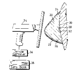
Figure 1 is a perspective view of a breast implant
contA~n~ng a passive transpon~r with a hand held reader
in position to read the ~nco~P~ data cont~i nP~ therein;
Figure 2 is a partial cross-sectional view of the
transpon~Pr as laminated between the multiple layers of a
seal patch for a breast implant;
Flgure 3 is a perspective view of a ~e~o~alis
muscle implant with a passive transpon~er mounted there-
10 in;
Figure 4 is a perspective view of a soft chin im-
plant with passive transpon~er mounted therein;
Figure 5 is a perspective view of a rigid chin
implant with a passive transponder mounted therein;
Figure 6 is a ~eLx~ective view of a nipple trans-
plant with a passive transponder mounted therein;
Figure 7 is a pe~s~e~Live view of an otoplasty
implant with a passive transpo~r mounted therein;
Figure 8 is a ~Lx~e~Live view of a pen~ 19 im-
20 plant, surgically implanted, with a passive transpon~rmounted therein;
Figure 9 is a top view of a pace maker with a pas-
sive tranSpon~er mounted theLeo--;
Figure 10 is a top view of a heart valve with a
25 passive transponder mounted to the edge thereof;
Figure 11 is a peL~ecLive view of a total knee
~oint prosthesis with a passive transponder mounted
thereon;
Figure 12 is a peLs~e~Live view of a shoulder ar-
30 throplasty system wlth a passive transpon~er mountedtherein;
Figure 13 is a partial cross-sectional view of a
passive transponder inlaid into and below the surface of
an implant:
CA 02223~72 1997-12-04
W O 96~9099 PCTAEP96/01349
Figure 14 is a perspective view of a femoral fixa-
tion system implanted in a femur with a passive trans-
ron~r mounted thereto:
Figure 15 is a perspective view of an orthopedic
S nailing system with a passive trans~sn~r mounted there-
in;
Figure 16 is a perspective view of a finger joint
~LO~ Lhe~ic with a passive transrsnAer mounted therein;
Figure 17 is a perspective view of a craniomaxil-
10 lofacial plating system with a passive transpon~er mount-
ed therein;
Figure 18 is a perspective view of still another
plating system with a passive tran~ pr mounted there-
in;
Figure 19 is a partial cross-sect~on~l view of a
typical implant with a passive transpo~r mounted within
a cored hole drilled therein;
Figure 20 is a perspective view of a drug release
implant with a passive transrsn~r affixed thereto; and
Figure 21 is a partially cu~a ay view of an organ
d~srlA~ement device with a passive transpon~r mounted
therein.
Detailed Descri~tion of the Preferred Embodiment
As shown in Figure 1, a breast implant 20 has been
25 implanted in a female's breast 22 and includes a silicone
shell 24 inflated with an ap~lu~ iate fill material 26.
At the posterior side of the implant 20 is shown the
transpon~?r 28 which has been laminated between ad~acent
layers 30, 32 of the shell 24. Transpo~ 28 may be any
30 passive transpsn~Dr such as a Trovan Model ID100 avail-
able from Electronic Identification Systems Ltd. of Santa
Barbara, California. This particular transpon~r is
designed to be environmentally ~dep~ndent and suitable
for operation while being directly submerged in liquids.
35 Furthermore, it may be read spherically from any direc-
CA 02223~72 1997-12-04
W096~99 PCT~P96/01349
tion through most materials, and including most impor-
tantly those materials comprising implants for the human
body. The transponAPr may be directly ~nc-o~e~ with 64
binary bits or more of data to provide almost one tril-
5 lion possible different code combinations. The limit ofdata ,e~,ded is a function of the further ~oy~ess and
development of ele~lollic memory terhnology. It is
anticipated that FDA a~oval will be forthcoming for its
use as part of the invention ~lcclo-s~A and claimed
lO herein.
A hand held reader 34 is also shown in Figure l
and may be a Trovan Model LID500, or other suitable de-
vice. Its principle of operation includes emitting a low
frequency magnetic field for activating the passive tran-
15 spqnA-r 28. As such, transronA~r 28 has no power source
and instead derives the energy nePA~A for its operation
from the magnetic field generated by the reader 34. This
permits the tranSponA~r 28 to have a virtually unlimited
life span. The hand held reader 34 is shown ronnected to
20 a Aec~A~r controller 36 which ~cce-cce-s a data bank 38 in
~-1~'~ to the deLec~ed code contA1neA within transpond-
er 28 to thereby Acr-~ss such data which has been stored
correspond1ng to transpon~er 28. Alternately, as men-
t1o~eA above, the hand held reader 34 may be used to ac-
25 cess the code contAlne~ within tranxl~ Aer 28 and then
other means used to ~ccesc a data bank for the retrieval
of the desired information. Such means might include the
use of a telepbone and modem to Acr~cs a registry con-
tAlne~ in a yeGy~a~hically centrally located site.
As shown in Figure 2, the transpon~-r 28 may be
laminated between ad~acent layers 40, 42 of the seal
patch 44 which is commonly used to seal the mandrel open-
ing 46 in a shell 48 of a breast implant 50. For other
implants, convenient mounting locations may be readily
35 determined with due consideration given to avoiding dis-
CA 02223~72 1997-12-04
W O 96~9099 PCT~EP96tO1349
comfort to the patient as well as optimizing readability
of the transpo~Aer with the hand held reader.
As shown in Figure 3, a pectoralis muscle implant
52 may conveniently have a passive transpo~r 54 con-
5 tA1nP~ therein. The passive transpon~er 54 may be moldedin place, or a hole or inlay drilled for placement of the
implant, after which the implant surface may then be
ref~ n~ ~h~ .
As shown in Figures 4 and 5, a soft chin implant
10 56 or a hard chin implant 58 may also have a passive
transpo~de- 60, 62 mounted therein. As shown in Figure
6, a nipple implant 64 has a passive transpo~d~r 66
mounted internally. In all of these transplants, the
mounting of the passive transpon~Dr is achieved to pro-
15 vide minimal discomfort or sensation to the patient, aswell as to avoid interference with the cosmetic appear-
ance of the implant. As shown in Figure 7, an otoplActy
implant 68 may have a passive transpon~Pr 70 mounted
therein. As shown in Figure 8, a penile implant 72 may
20 have a passive transpon~er 74 mounted therein.
As shown in Figure 9, a pace maker 76 may also
have a passive transpon~er 78 mounted either on its sur-
face or below the protective metal casing thereof. The
inventors have found that rPAA'I ng of the passive tran-
25 spon~er by the hand held reader may be achieved even whenthe transpon~P,r is obscured by metallic surfaces. As
shown in Figure 10, a heart valve 80 may have a passive
transpon~er 82 mounted to its edge in order to avoid
interference with the operability thereof, or fixation
30 thereof.
As shown in Figures 11 and 12, a total knee joint
prosthesis 84 or a shoulder prosthe~is 86, either one of
which includes a ma~ority of parts made from titanium or
the like, may also ~ollv~liently carry a passive trans-
35 ponder 88, 90.
CA 02223~72 1997-12-04
W096/39099 PCT~P96/01349
As shown in Figure 13, the passive transpon~r 92
may be placed within a trough 94 or the like and covered
with a QeAl~nt 96 so that the surface of the transpon~er
98 is uninterrupted and smooth as is desirable in many
5 tr~ncpon~?rs.
As shown in Figures 14 and 15, a femoral fixation
implant 100, or an orthopedic n~ ng system 102 may
.~v~,liently have a passive transron~r 104, 106 inlaid
therein. As shown in Figure 16, a finger joint ~lG~he-
10 sis 108 may also have a passive transpon~or llO locatedin a position which does not interfere with the movable
joint portion 112 of the prosthes~ 108. As shown in
Figures 17 and 18, a craniomaxillofacial plating system
114 or any other plating system 116 may also ~ eniently
15 include a passive trAneronAor 118, 120. As an alterna-
tive to the inlay mounting shown in Figure 13, a hole 122
may be drilled in any ~onv~.~ient location of an implant
124 and the passive transponder 126 inserted therein and
~alo-d in place by seAl~r 128, with the outer surface of
20 s~ler 128 being finished to provide a smooth surface on
implant 124, as shown in Figure 19.
A passive transpon~er may also be utilized with
implants inte~ed for temporary implantation in humans
including, but not limited to, drug reloAso implants and
25 organ displacement devices. As shown in Figure 20, a
drug release implant 130 may have a transp~nder 132
mounted thereto in such a manner that transronAQr 132
does not interfere with the controlled role~e of a drug
from the implant 130. The transpo~or 132 may contain a
30 code relatlng to information such as the date of
implantation, the type of drug cont~ no~ in the implant
130, and the date when the implant 130 should be removed
or replaced. As shown in Figure 21, an organ
displacement device 134 may have a passive transpondor
35 136 affixed to the interior surface of the device such
that the transpondor 136 does not interfere with the
CA 02223~72 1997-12-04
W096~90g9 PCT~P96/01349
inflation or deflation of the organ displacement device
134, or wlth the therapeutic process for which the device
134 is being used. In this case, the passive transp~nd~r
136 may contain a code relating to information such as
5 the date of implantation and the particular type of organ
displacement device, as well as information pert~ n~ ng to
the history of the therapy undergone by the patient in
which the organ displacement device is implanted.
Altho~gh all of the implants ment~o~eA above have
10 been described as having a passive transronAPr mounted to
the interior or the exterior of the part~rl~lAr device,
other ac~ey~able methodologies for Assoc~Ating the
transponA~r with the implants are avA~lAhle. Examples of
these alternative methods include ut~l~ 7~ ng a non-
15 absorbable string and basket tether or by locating the
trAncronA~r according to an ad~acent site StAnAArd. In
the case of uff l~7~g the ad~acent site stAnA~rd, the
slte may be in close prox$mity to the implant or in a
stAnAArdized location that may be device specific.
In addition to uff l~ 7~ ng a passive transro~Aer in
con~unction with an implant to identify the part~cl~lAr
implant and retrieve data relating to the implant and
patient, the passive transponder can also be ut~l~ 7eA to
locate the particular implant in cases where the implant
25 is su~e~ible to movement within the patient's body overa period of time, or where the att~nA~ng meA~cAl
pel~o~-el are otherwise u,~ aln as to the position of
the implant within the patient's body. For example,
where a drug release implant is implanted into a patient
30 for several months or years, the implant may move from
the position in the patient's body where the implant was
originally plA~-~A. Hence, the part~lllAr location of the
implant must be ascertA~neA before the implant can be
removed. Similarly, an organ displacement device may be
35 susceptible to movement within a patient's body during
the period of time between s~cc~ssive therapeutic
CA 02223~72 1997-12-04
W096~9099 PCT~P96/01349
treatments. Because these devices may be inflated in
situ after implantation but prior to a therapeutic
treatment, and then deflated thereafter, the precise
location of the organ displacement device, as well as an
5 inflation/deflation valve associated therewith, must be
ascert~neA prior to performing these proceA~res, as well
as prior to removal of the device.
In these cases, the passive transponAPr ~scoc~ated
with an implant can be ut~l~ 7eA to locate the specific
lO positlon of the implant in the patient's body. 8y
ut~ ng an electromagnetic reader having a strength-of-
signal meter, the reader can be used to externally scan
over a portion of the patient's body where the implant is
generally e~yec~ed to be located. By referring to the
15 strength-of-Q~g~l meter on the electromagnetic reader,
the specific location of the implant can be ascert~ineA.
This specific location will correspond to the location on
the patient's body where the electromagnetic reader
generated the s~o.~yest read s~gn~l. In other words, as
20 the electromagnetic reader appro~ch~s the external
position of the body that corresponds to the internal
location of the implant and transponA~r, the ~ LL el~yLh of
the read s~gnAls generated by the electromagnetic reader,
and ~ nA ~ c~ted thereon, will increase. As the reader
25 moves away from this external position of the body, the
51,1e~ h of the read signals will decrease. In this
manner, the electromagnetic reader and transronAer can be
ut~ 1~ 7eA to find an implant. Where the transpon~r is
used in this manner for the purpose of subsequently
30 locating the position of the implant in the patient's
body, the transpo~A~r may be en~n~A with a simple code
or tag solely for this purpose, or may additionally be
e~coA~A to identify particular information about the
implant and patient, as described above.
As disclosed herein, a wide variety of implants
made of all sorts of material may conveniently include a
.
CA 02223~72 1997-12-04
W O 96/39099 PCTrEP96/01349
passive transpon~r which may be implanted, and then read
by the hand held reader. This compatibility and ease of
operation permits the use of a passive transponder with
virtually any implant. The inventors have disclosed
5 herein a representative sample of such implants. Howev-
er, the scope of the present invention is broad enough to
encompass any implant presently known to the inventors
hereln.
There are various changes and modifications which
10 may be made to the invention as would be apparent to
those skilled in the art. However, these changes or
modifications are included in the t~ch~g of the disclo-
sure, and it is int~A~ that the invention be limited
only by the scope of the claims app~nA~A hereto.