Language selection

Search

Patent 2224350 Summary

Third-party information liability

Some of the information on this Web page has been provided by external sources. The Government of Canada is not responsible for the accuracy, reliability or currency of the information supplied by external sources. Users wishing to rely upon this information should consult directly with the source of the information. Content provided by external sources is not subject to official languages, privacy and accessibility requirements.

Claims and Abstract availability

Any discrepancies in the text and image of the Claims and Abstract are due to differing posting times. Text of the Claims and Abstract are posted:

  • At the time the application is open to public inspection;
  • At the time of issue of the patent (grant).
(12) Patent: (11) CA 2224350
(54) English Title: GASKET INSERT AND METHOD OF MAKING SAME
(54) French Title: INSERT DE JOINT D'ETANCHEITE ET SA METHODE DE FABRICATION
Status: Expired and beyond the Period of Reversal
Bibliographic Data
(51) International Patent Classification (IPC):
  • F16J 15/12 (2006.01)
  • B21D 53/00 (2006.01)
  • F02F 11/00 (2006.01)
(72) Inventors :
  • SCHWEIGER, DAVID J. (United States of America)
(73) Owners :
  • DANA CORPORATION
  • DANA AUTOMOTIVE SYSTEMS GROUP, LLC
(71) Applicants :
  • DANA CORPORATION (United States of America)
  • DANA AUTOMOTIVE SYSTEMS GROUP, LLC (United States of America)
(74) Agent: SMART & BIGGAR LP
(74) Associate agent:
(45) Issued: 2007-09-25
(22) Filed Date: 1997-12-08
(41) Open to Public Inspection: 1998-06-10
Examination requested: 2002-11-08
Availability of licence: N/A
Dedicated to the Public: N/A
(25) Language of filing: English

Patent Cooperation Treaty (PCT): No

(30) Application Priority Data:
Application No. Country/Territory Date
08/763,266 (United States of America) 1996-12-10

Abstracts

English Abstract


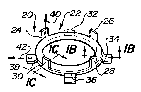
A gasket insert including a carrier having at least two retaining arms. The
retaining
arms are adapted to contact opposing faces of a gasket material to form a
mechanical means
of fastening the gasket insert to a gasket body. Also disclosed is a method of
making a gasket
insert including forming a carrier body from a steel stamping and folding the
steel stamping
upon itself to create a double layered carrier body. The carrier body is
fitted with retaining
arms for gripping the gasket body and is fitted with a plurality of passages
for filling with
sealing material and forming a positive means of mechanically bonding sealing
material to
the carrier body.


Claims

Note: Claims are shown in the official language in which they were submitted.


7
We claim:
1. A gasket insert, comprising:
a one-piece carrier body comprised of a steel stamping folded upon itself,
said carrier body including an outer surface covered with a sealing material,
a first retaining arm having an end portion which extends from said carrier
body in a first direction,
a second retaining arm having an end portion which extends from said carrier
body in a second direction, and
wherein said first direction is generally perpendicular to said second
direction.
2. The gasket insert of claim 1, wherein said sealing material is selected
from
the group of rubber and silicone.
3. A gasket assembly, comprising:
a gasket body having at least one opening therein,
a one-piece carrier body disposed in said gasket body opening, said carrier
body comprised of a steel stamping folded upon itself including a first
retaining arm
having an end portion which extends from said carrier body in a first
direction in a
first plane, said carrier body also including
a second retaining arm having an end portion which extends from said carrier
body in a second direction in a second plane, wherein said first and second
planes
are spaced apart, and
wherein said carrier body further includes an outer surface covered with a
sealing material.
4. The gasket insert of claim 3, wherein said sealing material is selected
from
the group of rubber and silicone.
5. A gasket insert, comprising:
a one-piece carrier body comprised of a steel stamping folded upon itself,

8
a plurality of passages extending through said carrier body,
a first retaining arm having an end portion which extends from said carrier
body in a first direction,
a second retaining arm having an end portion which extends from said carrier
body in a second direction, and
wherein said first direction is generally perpendicular to said second
direction.
6. The gasket insert of claim 5, wherein said carrier body includes an outer
surface coated with a sealing material and wherein said plurality of passages
contain said sealing material.
7. A gasket assembly, comprising:
a gasket body having at least one opening therein,
a one-piece carrier body disposed in said gasket body opening, said carrier
body comprised of a steel stamping folded upon itself including a first
retaining arm
having an end portion which extends from said carrier body in a first
direction in a
first plane, said carrier body also including
a second retaining arm having an end portion which extends from said carrier
body in a second direction in a second plane, wherein said first and second
planes
are spaced apart, and
wherein said carrier body further includes a plurality of passages
therethrough.

Description

Note: Descriptions are shown in the official language in which they were submitted.


CA 02224350 1997-12-08
60680-1016(3804VIC) 1
GASKET INSERT AND METHOD OF MAKING SAME
FIELD OF THE INVENTION
The present invention generally relates to gaskets and more particularly
relates to
gasket inserts.
BACKGROUND OF THE INVENTION
In designing gaskets it is common to incorporate transfer seals (or also known
as
inserts) into the gasket body. Transfer seals are used to accommodate fluid
flow between two
members and act to prevent the fluid from seeping between the mating surfaces
of the two
members. Transfer seals are often used in automotive head gaskets where the
fluid flowing
between the engine head and the engine block may be engine coolant or engine
lubricating
oil.
Although transfer seals have been used for sometime, there still does not
exist a highly
reliable method of attaching a transfer seal to a gasket body. Current
attachment techniques
include the use of adhesives or press fitting a molded insert into the gasket
body. Use of
Adhesives tends to be unreliable and they are especially prone to failure
during shipping of
the gasket (prior to installing the gaskets). Accordingly, inserts which have
been attached to
the gasket body by way of adhesives, generally require that the gaskets be
handled and
transported in a delicate manner.
SUMMARY OF THE INVENTION
The present invention is directed to a gasket insert which includes a carrier
body and
first and second retaining arms extending from the carrier body. The first
retaining arm
includes an end portion which extends from the carrier body in a first
direction and the
second retaining arm includes an end portion which extends from the carrier
body in a second
direction. The first direction is generally perpendicular to the second
direction.

CA 02224350 1997-12-08
60680-1016(3804VIC) 2
The present invention is also directed to a gasket assembly including a gasket
body
and a carrier body. The carrier body is disposed in an opening in the gasket
body and the
carrier body includes first and second retaining arms. First retaining arm has
an end portion
which extends from the carrier body in a first direction in a first plane and
the second
retaining arm includes an end portion which extends from the carrier body in a
second
direction in a second plane. The first and second planes are spaced apart.
Also, the present invention includes a method of making a gasket insert
including
forming an opening in a piece of generally planar sheet metal and shaping the
opening such
that it includes inwardly pointing retaining arms. Next, a metal in the area
surrounding the
opening is drawn away from the generally planar piece of sheet metal such that
it forms a
cylindrical column rising above the generally planar piece of sheet metal. The
next step is
accomplished by deforming the cylindrical column to hold against the generally
planar piece
of metal such that the inwardly pointing fingers are made to point outwardly.
Lastly, the
piece is severed from a generally planar piece of sheet metal in a manner such
that a second
set of outwardly pointing retaining arms are formed along a periphery of said
severed piece.
BRIEF DESCRIPTION OF THE DRAWINGS
The features and inventive aspects of the present invention will become more
apparent
upon reading the following detailed description, claims, and drawings of which
the following
is a brief description:
Figure 1A is a perspective view of the gasket insert of the present invention.
Figure 1B is a cross-sectional view taken substantially along lines lB-lB of
Figure
1A.
Figure 1C is a cross-sectional view taken substantially along lines 1C-1C of
Figure
1 A.

CA 02224350 1997-12-08
60680-1016(3804VIC) 3
Figure 2A is a bottom view of the carrier body portion of the gasket insert of
Figure
l A.
Figure 2B is a cross-section view taken substantially along lines 2B-2B of
Figure 2A.
Figure 2C is a partial cross-sectional view taken substantially along lines 2C-
2C of
Figure 2A.
Figures 3-6 depict the method steps for fabricating the carrier body of Figure
2A.
Figure 7 depicts the method step of coating the carrier body of Figure 2A with
a
sealing material.
Figure 8 is a perspective view of the combination of a gasket body combined
with the
gasket insert of Figure 1 A.
Figure 9 is a top view of a gasket assembly of Figure 8.
Figure l0A is a partial cross-section view taken substantially along lines 10A-
10A of
Figure 9.
Figure lOB is a partial cross-sectional view taken substantially along lines
lOB-lOB of
Figure 9.
Figure lOC is a partial cross-sectional view taken substantially along lines
lOC-lOC of
Figure 9.

CA 02224350 1997-12-08
60680-1016(3804VIC) 4
DETAILED DESCRIPTION OF THE PREFERRED EMBODIMENTS
The gasket insert 20 of the present invention includes carrier 22, first
retaining arms
24-30, and second retaining arms 32-38. First retaining arms 24-30 each have
an end portion
which extends from carrier 22 in an axial direction 40 (for the sake of
clarity axial direction
40 is only specifically labeled with respect to first retaining arm 24).
Second retaining arms
32-38 extend from the carrier in a radial direction 42 (for the sake of
clarity only second
retaining arm 38 is specifically labeled showing radial direction 42).
Now referring to Figures 1 A-1 C and 2A-2C, carrier 22 is preferably comprised
of
stamped steel carrier body 44 which is covered with sealing material 46.
Carrier body 44
includes a plurality of passages 48 (not shown in Figures 1B and 1C; but see
Figure 2A ).
These passages allow the free flow of sealing material therethrough during its
application (in
liquid form) to carrier body 44. Once sealing material 46 solidifies, it is
trapped within
passages 48 and forms a secure mechanical bond to carrier body 44. Sealing
materia146 can
be comprised of any number of materials which are commonly used in the
fabrication of
transfer seals in gaskets including rubber and silicone.
Now referring to Figures 3-6, carrier body 44 is preferably fabricated using
the
following method:
1) An opening 52 formed in a generally planar steel sheet 50. Opening 52 is
preferably formed by way of a piercing operation. Opening 52 includes inwardly
pointing
retaining arms 24-30 (see Figure 3). Also included are four holes 51 required
to facilitate
subsequent severing operation set forth in Step 4.
2) Next, the portion steel sheet 50 in the vicinity of opening 52 is drawn
away
from the plane in which the generally planar piece of sheet metal 50 lies such
that the drawn
portion forms a cylindrical column 56 rising above generally planar piece of
sheet metal 50
(see Figures 4 and 5).

CA 02224350 1997-12-08
60680-1016(3804VIC) 5
3) Cylindrical column 56 is then deformed toward generally planar steel sheet
50
such that it is folded against sheet 50 in a way which causes inwardly
pointing fingers 24-30
to reorient themselves and point outwardly (see Figure 6).
4) Lastly steel carrier body 44 is severed from steel sheet 50 along a
periphery
defined by dotted line 58 (see Figure 6). Arms 24-30 are not severed but
rather they are left
in place.
Additionally, passages 48 (see Figure 2A) are formed in carrier body 44
(preferably by
way of a piercing operation) and retaining arms 24-30 are bent from their
outwardly
extending orientation shown in Figure 6 to their perpendicular orientation as
depicted in
Figure 2A. Preferably, the shearing, piercing, and bending operations are
performed in a
single step.
Now referring to Figure 7, after the stamped steel carrier body 44 of Figure
2A is
formed, it is placed within injection mold cavity 64 of mold 60. Thereafter,
sealing material
46 is injected (in a liquid state) into cavity 64, which surrounds carrier
body 44, (but sealing
material 46 is not allowed to flow against retaining arms 24-38). During its
liquid state,
sealing materia146 flows freely through sprue 62 and encircles carrier body
44. Once sealing
material 46 solidifies mold halves 66, 68 are separated 70, 72 and the
finished gasket insert
20 is removed.
The gasket assembly of the present invention includes gasket body 76 and
gasket
insert 20 disposed within an opening in gasket body 76.
Now referring to Figures lA, 8,9, 10A, lOB and IOC, order to mount gasket
insert 20
within opening 78 of gasket body 76, gasket insert 20 is oriented such that
first retaining arms
24-30 are proximate opening 76 and retaining arms 32-38 are distal opening 76.
Next, gasket
insert 20 is moved 84 through opening 76 until retaining arms 32-38 abut the
bottom surface
80 of gasket body 76 (second retaining arms 32-38 not shown in Figure 8).
Next, first

CA 02224350 1997-12-08
60680-1016(3804VIC) 6
retaining arms 24-30 are bent downwardly until they each abut top surface 82
of gasket body
76.
Now referring to Figures 8, 9, 10A-10C, once gasket insert 20 is fastened to
gasket
body 76 and first retaining arms 24-30 are bent against top surface 82 of
gasket body 76, the
orientation of first retaining arms 24-30, is such that they all lie in a
first plane defined by
upper surface 82 (see Figure 9). Also, from Figures 6, 9, and 10A, it is
demonstrated that
second retaining arms 32, 34, 36 and 38 all lie in a second plane defined by
bottom surface 80
of gasket body 76. The first plane and the second plane are separated by a
distance
approximately equal to the thickness of gasket body 76.
Now referring to Figure 9, retaining arm 32 generally extends along the
direction
indicated by ray 86. Retaining arm 26 generally extends in the direction
indicated by ray 88.
Ray 86 and ray 88 differ in angular direction as indicated by angle 90 having
an origin at 92.
Thus, although retaining arms 32, 26 lie in generally parallel, spaced apart
planes (defined by
surfaces 80, 82 respectively), they are staggered 90 along the periphery of
carrier 22, and
extend in different directions 86, 88.
Preferred embodiments of the present invention have been disclosed. A person
of
ordinary skill in the art would realize, however, that certain modifications
would come with
the teachings of this invention. Therefore, the following claims should be
studied to
determine the true scope and content of the invention.

Representative Drawing
A single figure which represents the drawing illustrating the invention.
Administrative Status

2024-08-01:As part of the Next Generation Patents (NGP) transition, the Canadian Patents Database (CPD) now contains a more detailed Event History, which replicates the Event Log of our new back-office solution.

Please note that "Inactive:" events refers to events no longer in use in our new back-office solution.

For a clearer understanding of the status of the application/patent presented on this page, the site Disclaimer , as well as the definitions for Patent , Event History , Maintenance Fee  and Payment History  should be consulted.

Event History

Description Date
Time Limit for Reversal Expired 2010-12-08
Letter Sent 2009-12-08
Letter Sent 2009-03-18
Grant by Issuance 2007-09-25
Inactive: Cover page published 2007-09-24
Inactive: Final fee received 2007-07-10
Pre-grant 2007-07-10
Notice of Allowance is Issued 2007-01-17
Letter Sent 2007-01-17
Notice of Allowance is Issued 2007-01-17
Inactive: Approved for allowance (AFA) 2006-12-01
Amendment Received - Voluntary Amendment 2006-09-06
Inactive: S.30(2) Rules - Examiner requisition 2006-03-06
Amendment Received - Voluntary Amendment 2003-03-24
Letter Sent 2002-12-23
Request for Examination Requirements Determined Compliant 2002-11-08
All Requirements for Examination Determined Compliant 2002-11-08
Request for Examination Received 2002-11-08
Application Published (Open to Public Inspection) 1998-06-10
Classification Modified 1998-05-02
Inactive: IPC assigned 1998-05-02
Inactive: First IPC assigned 1998-05-02
Inactive: IPC assigned 1998-05-02
Inactive: IPC assigned 1998-04-22
Inactive: Filing certificate - No RFE (English) 1998-03-09
Letter Sent 1998-03-09
Application Received - Regular National 1998-03-09

Abandonment History

There is no abandonment history.

Maintenance Fee

The last payment was received on 2006-11-23

Note : If the full payment has not been received on or before the date indicated, a further fee may be required which may be one of the following

  • the reinstatement fee;
  • the late payment fee; or
  • additional fee to reverse deemed expiry.

Patent fees are adjusted on the 1st of January every year. The amounts above are the current amounts if received by December 31 of the current year.
Please refer to the CIPO Patent Fees web page to see all current fee amounts.

Owners on Record

Note: Records showing the ownership history in alphabetical order.

Current Owners on Record
DANA CORPORATION
DANA AUTOMOTIVE SYSTEMS GROUP, LLC
Past Owners on Record
DAVID J. SCHWEIGER
Past Owners that do not appear in the "Owners on Record" listing will appear in other documentation within the application.
Documents

To view selected files, please enter reCAPTCHA code :


To view images, click a link in the Document Description column. To download the documents, select one or more checkboxes in the first column and then click the "Download Selected in PDF format (Zip Archive)" or the "Download Selected as Single PDF" button.

List of published and non-published patent-specific documents on the CPD .

If you have any difficulty accessing content, you can call the Client Service Centre at 1-866-997-1936 or send them an e-mail at CIPO Client Service Centre.


Document
Description 
Date
(yyyy-mm-dd) 
Number of pages   Size of Image (KB) 
Representative drawing 1998-06-08 1 6
Abstract 1997-12-07 1 19
Description 1997-12-07 6 229
Claims 1997-12-07 3 75
Drawings 1997-12-07 2 77
Claims 2006-09-05 2 63
Representative drawing 2007-08-28 1 11
Courtesy - Certificate of registration (related document(s)) 1998-03-08 1 118
Filing Certificate (English) 1998-03-08 1 165
Reminder of maintenance fee due 1999-08-09 1 114
Reminder - Request for Examination 2002-08-11 1 127
Acknowledgement of Request for Examination 2002-12-22 1 174
Commissioner's Notice - Application Found Allowable 2007-01-16 1 161
Maintenance Fee Notice 2010-01-18 1 170
Fees 2002-11-19 1 32
Fees 2003-11-18 1 31
Fees 2000-11-21 1 31
Fees 2001-11-18 1 31
Fees 1999-09-23 1 28
Fees 2004-11-17 1 26
Fees 2005-11-17 1 26
Fees 2006-11-22 1 29
Correspondence 2007-07-09 1 27