Language selection

Search

Patent 2224550 Summary

Third-party information liability

Some of the information on this Web page has been provided by external sources. The Government of Canada is not responsible for the accuracy, reliability or currency of the information supplied by external sources. Users wishing to rely upon this information should consult directly with the source of the information. Content provided by external sources is not subject to official languages, privacy and accessibility requirements.

Claims and Abstract availability

Any discrepancies in the text and image of the Claims and Abstract are due to differing posting times. Text of the Claims and Abstract are posted:

  • At the time the application is open to public inspection;
  • At the time of issue of the patent (grant).
(12) Patent: (11) CA 2224550
(54) English Title: MAGNETIC WINGED SOCKET WRENCH
(54) French Title: CLE A DOUILLE A AILETTES MAGNETIQUE
Status: Expired and beyond the Period of Reversal
Bibliographic Data
(51) International Patent Classification (IPC):
  • B25B 23/12 (2006.01)
  • B25B 13/06 (2006.01)
  • B27B 5/32 (2006.01)
(72) Inventors :
  • BERNEL, ENRIQUE HENRY (Canada)
(73) Owners :
  • ENRIQUE HENRY BERNEL
(71) Applicants :
  • ENRIQUE HENRY BERNEL (Canada)
(74) Agent: DOUGLAS B. THOMPSONTHOMPSON, DOUGLAS B.
(74) Associate agent:
(45) Issued: 2001-08-14
(22) Filed Date: 1998-02-24
(41) Open to Public Inspection: 1999-08-24
Examination requested: 1998-02-24
Availability of licence: N/A
Dedicated to the Public: N/A
(25) Language of filing: English

Patent Cooperation Treaty (PCT): No

(30) Application Priority Data: None

Abstracts

English Abstract


A socket wrench includes a generally cylindrical main
body having a socket. A pair of opposed arms extending
radially from the main body.


Claims

Note: Claims are shown in the official language in which they were submitted.

4
THE EMBODIMENTS OF THE INVENTION IN WHICH AN EXCLUSIVE PROPERTY
OR PRIVILEGE IS CLAIMED ARE DEFINED AS FOLLOWS:
1. A socket wrench, comprising:
a truncated generally cylindrical main body having a socket;
a magnet positioned at a remote end of the socket; and
a pair of opposed arms extending radially from the main
body.
2. A combination, comprising:
a power saw having a saw blade held in place by a rotatable
fastener; and
a socket wrench, including:
a truncated generally cylindrical main body having a
socket;
a magnet positioned at a remote end of the socket; and
a pair of opposed arms extending radially from the main
body;
the socket wrench being detachably secured to the power saw
while the power saw is in use, by magnetically adhering the
magnet at the remote end of the socket to the fastener.

Description

Note: Descriptions are shown in the official language in which they were submitted.


CA 02224550 2000-10-10
1
TITLE OF THE INVENTION:
Socket Wrench
NAMES) OF INVENTOR(S):
Enrique Bernel
FIELD OF THE INVENTION
The present invention relates to a socket wrench.
BACKGROUND OF THE INVENTION
The preferred tool for removing a fastener that secures
a rotary blade to a power saw is a socket wrench. When other
tools are used, such as a crescent wrench or a pair of pliers,
the fastener can become damaged. It is not practical, however,
to store with a power saw a conventional socket wrench set
having a handle, an adaptor and a plurality of alternative
detachable sockets. A more specialized tool is required.
SUMMARY OF THE INVENTION
What is required is an alternative form of socket wrench.
According to the present invention there is provided a
socket wrench which includes a generally cylindrical main body
having a socket . A pair of opposed arms extending radially
from the main body.
A rotatable fastener can be positioned in the socket of
the socket wrench, described above, and the body rotated by
means of the opposed arms to tighten or loosen the fastener.
The socket wrench, as described, is compact and efficient to
perform a specialized task.
Although beneficial results can be obtained through the
use of the socket wrench, as described above, even more
beneficial results may be obtained when a magnet is positioned
at a remote end of the socket. The magnet holds the socket
wrench in position on the rotatable fastener. This enables the

CA 02224550 2000-10-10
' 2
user to adjust his or her hand position during use. It also
provides an option of leaving the wrench magnetically attached
to the fastener during transport or, in appropriate
circumstances, during use.
BRIEF DESCRIPTION OF THE DRAWINGS
These and other features of the invention will become more
apparent from the following description in which reference is
made to the appended drawings, wherein:
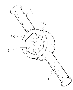
FIGURE 1 is a perspective view of a socket wrench
constructed in accordance with the teachings of the present
invention.
FIGURE 2 is a side elevation view of the socket wrench
illustrated in FIGURE 1.
FIGURE 3 is a bottom plan view of the socket wrench
illustrated in FIGURE 1.
FIGURE 4 is a top plan view of the socket wrench
illustrated in FIGURE 1.
FIGURE 5 is an end elevation view of the socket wrench
illustrated in FIGURE 1.
FIGURE 6 is a side elevation view, in section, of the
rocket wrench illustrated in FIGURE 1.
DETAILED DESCRIPTION OF THE PREFERRED EMBODIMENT
The preferred embodiment, a socket wrench generally
identified by reference numeral 10, will now be described with
reference to FIGURES 1 through 6.
Referring to FIGURE l, socket wrench 10 has a generally
cylindrical main body 12 with a socket 14. Depending upon the
intended application, socket 14 will vary in size and
configuration. A pair of opposed arms 16 extend radially from
main body 12. Referring to FIGURE 6, a magnet 18 is positioned
at a remote end 20 of socket 14.
The use and operation of socket wrench 10 will now be

CA 02224550 2000-10-10
3
described with reference to FIGURES 1 through 6. Referring to
FIGURE 6, a fastener 22 is illustrated which, together with a
positioning washer 24 holds a saw blade 26 onto a power saw 28.
In order to tighten or loosen fastener 22, socket 14 in main
body 12 is positioned over fastener 22. Once socket 14 is
positioned over fastener 22, main body is held in position by
magnetic attraction between fastener 22 and magnet 18. Main
body 12 is then rotated by means of opposed arms 16 to tighten
or loosen fastener 22.
Socket wrench 10 facilitates the rapid removal of fastener
2.2 so that saw blade 26 can be replaced. It does so without
causing damage to fastener 22. It is preferred fastener 22 be
left in place magnetically attached to fastener 22 of power saw
2 8 at all times . When maintained as a combination considerable
time can be saved at construction sites in replacing saw
blades.
It will be apparent to one skilled in the art that
modifications may be made to the illustrated embodiment without
departing from the spirit and scope of the invention as
hereinafter defined in the Claims.

Representative Drawing
A single figure which represents the drawing illustrating the invention.
Administrative Status

2024-08-01:As part of the Next Generation Patents (NGP) transition, the Canadian Patents Database (CPD) now contains a more detailed Event History, which replicates the Event Log of our new back-office solution.

Please note that "Inactive:" events refers to events no longer in use in our new back-office solution.

For a clearer understanding of the status of the application/patent presented on this page, the site Disclaimer , as well as the definitions for Patent , Event History , Maintenance Fee  and Payment History  should be consulted.

Event History

Description Date
Inactive: IPC from MCD 2006-03-12
Time Limit for Reversal Expired 2005-02-24
Letter Sent 2004-02-24
Inactive: Late MF processed 2003-02-20
Inactive: Adhoc Request Documented 2002-04-26
Letter Sent 2002-02-25
Grant by Issuance 2001-08-14
Inactive: Cover page published 2001-08-13
Pre-grant 2001-05-10
Inactive: Final fee received 2001-05-10
Notice of Allowance is Issued 2000-11-10
Letter Sent 2000-11-10
Notice of Allowance is Issued 2000-11-10
Appointment of Agent Requirements Determined Compliant 2000-11-01
Revocation of Agent Requirements Determined Compliant 2000-11-01
Inactive: Office letter 2000-11-01
Inactive: Approved for allowance (AFA) 2000-10-24
Revocation of Agent Request 2000-10-10
Appointment of Agent Request 2000-10-10
Amendment Received - Voluntary Amendment 2000-10-10
Inactive: S.30(2) Rules - Examiner requisition 2000-06-07
Inactive: Adhoc Request Documented 1999-12-20
Application Published (Open to Public Inspection) 1999-08-24
Inactive: Cover page published 1999-08-24
Inactive: IPC assigned 1998-03-30
Classification Modified 1998-03-30
Inactive: First IPC assigned 1998-03-30
Inactive: Filing certificate - RFE (English) 1998-03-11
Filing Requirements Determined Compliant 1998-03-11
Inactive: Office letter 1998-03-11
Application Received - Regular National 1998-03-10
Request for Examination Requirements Determined Compliant 1998-02-24
All Requirements for Examination Determined Compliant 1998-02-24

Abandonment History

There is no abandonment history.

Maintenance Fee

The last payment was received on 2001-02-23

Note : If the full payment has not been received on or before the date indicated, a further fee may be required which may be one of the following

  • the reinstatement fee;
  • the late payment fee; or
  • additional fee to reverse deemed expiry.

Please refer to the CIPO Patent Fees web page to see all current fee amounts.

Fee History

Fee Type Anniversary Year Due Date Paid Date
Request for examination - small 1998-02-24
Application fee - small 1998-02-24
MF (application, 2nd anniv.) - small 02 2000-02-24 1998-02-24
MF (application, 3rd anniv.) - small 03 2001-02-26 2001-02-23
Final fee - small 2001-05-10
Reversal of deemed expiry 2002-02-25 2003-02-20
MF (patent, 5th anniv.) - small 2003-02-24 2003-02-20
MF (patent, 4th anniv.) - small 2002-02-25 2003-02-20
Owners on Record

Note: Records showing the ownership history in alphabetical order.

Current Owners on Record
ENRIQUE HENRY BERNEL
Past Owners on Record
None
Past Owners that do not appear in the "Owners on Record" listing will appear in other documentation within the application.
Documents

To view selected files, please enter reCAPTCHA code :


To view images, click a link in the Document Description column. To download the documents, select one or more checkboxes in the first column and then click the "Download Selected in PDF format (Zip Archive)" or the "Download Selected as Single PDF" button.

List of published and non-published patent-specific documents on the CPD .

If you have any difficulty accessing content, you can call the Client Service Centre at 1-866-997-1936 or send them an e-mail at CIPO Client Service Centre.


Document
Description 
Date
(yyyy-mm-dd) 
Number of pages   Size of Image (KB) 
Abstract 1998-02-24 1 14
Description 1998-02-24 2 76
Claims 1998-02-24 1 13
Drawings 1998-02-24 13 406
Cover Page 1999-08-24 1 25
Cover Page 2001-07-31 1 26
Abstract 2000-10-10 1 7
Drawings 2000-10-10 7 271
Description 2000-10-10 3 110
Claims 2000-10-10 1 23
Abstract 2000-10-11 1 7
Description 2000-10-11 3 115
Claims 2000-10-11 1 26
Drawings 2000-10-11 7 273
Representative drawing 2001-07-31 1 7
Representative drawing 1999-08-24 1 4
Filing Certificate (English) 1998-03-11 1 165
Notice: Maintenance Fee Reminder 1999-11-25 1 119
Commissioner's Notice - Application Found Allowable 2000-11-10 1 165
Maintenance Fee Notice 2002-03-25 1 179
Late Payment Acknowledgement 2003-03-03 1 167
Maintenance Fee Notice 2004-04-20 1 173
Fees 2003-02-20 1 33
Correspondence 1998-03-11 1 23
Correspondence 2000-11-01 1 9
Correspondence 2000-10-10 3 101
Correspondence 2000-11-01 1 9
Correspondence 2001-05-10 1 36
Correspondence 2002-03-25 2 96
Fees 2001-02-23 1 30