Note: Descriptions are shown in the official language in which they were submitted.
CA 02224980 1997-12-17
W O97/01689 PCTr~S96/11238
TITLE: AUTOMATIC SWI~JIMING POOL CLEANING SYSTEM
FIELD OF THE INVENTION
c 5 The present invention relates to a method and apparatus suitable for
cleaning a swimming pool.
BACKGROUND OF THE INVENTION
The prior art is replete with differenl: types of automatic swimming pool
10 cleaners. They include water surface cleaning devices which typically float at the water
surface and can be moved across the water surface for cleaning, as by skimming. The
prior art also shows pool wall surface cleaning devices which can rest at the pool bottom
and can be moved along the wall (which term should be understood to include bottom
and side portions) for wall cleaning, as by vacuuming and/or sweeping. Some prior art
15 assemblies include both water surface cleaning and wall surface cleaning components
tethered together.
SUMMARY OF THE INVENTION
The present invention is directed to a method and apparatus useful for
20 cleaning a water pool contained in an open vessel defined by a wall having bottom and
side portions.
Apparatus in accordance with the invention includes (1 ) a unitary structure
or body capable of being immersed in a water pool and (2) a level control subsystem for
selectively moving the body to a position either proximate to the surface of the water
25 pool for water surface cleaning or proximate to the interior surface of the vessel wall for
wall surface cleaning.
Embodiments of the invention can use either a heavier-than-water body or
a lighter-than-water body. When a heavier-than-water body is used, the body in its
CA 02224980 1997-12-17
W O 97/01689 PCT~US96/11238
quiescent or rest state typically sinks to a position proximate to the bottom portion of
the vessel wall. In an active state, the level control subsystem produces a vertical foroe
component for lifting the body to proximate to the water surface for operation in a water
surface cleaning mode.
When a lighter-than-water body is used, the body in its quiescent state
floats at a position proximate to the water surface. In an active state, the level control
subsystem produces a vertical force component for causing the body to descend toproximate the wall bottom portion for operation in a wall surface cleaning mode.When in the water surface cleaning mode, debris is collected from the water
10 surface. When in the wall surface cleaning mode, debris is collected from the wall
surface.
Embodiments of the invention preferably also include a propulsion
subsystem for producing a nominally horizontal force component for moving the body
along (1) a path adjacent to the water surface when the body is in the water surfaoe
15 cleaning mode and (2) a path adjacent to the wall surface when the body is in the wall
surface cleaning mode.
Preferred embodiments of the invention are configured to be hydraulically
powered, either from the pressure or suction side of an external hydraulic pump.Proximal and distal ends of a flexible supply hose are respectively coupled to the pump
20 and body for producing a water supply flow through the body for powering the
aforementioned subsystems. The hose is preferably configured so that it typically
primarily lies close to the vessel interior wall surface with the hose distal end being
dragged along by the movement of the body.
More particularly, in the exemplary preferred embodiments, the water supply
25 flow is directed by one or more control elements (e.g., valve), to directly or indirectly,
create water flows for producing the vertical and horizontal force components
respectively needed for level control and propulsion. A preferred propulsion subsystem
can define either a normal state in which a force component is produced for moving the
CA 02224980 l997-12-l7
W O97/01689 PCTAUS96/11238
body in a forward direction, and a backup state for producing a force component for
moving the body in a rearward direction. Water surface and wall surface cleaningtypically occurs during the normal propulsion mode. The backup propulsion state is
preferably initiated to enable the body to free itself from obstructions.
~he body preferably carries a water permeable debris container. In the
water surface cleaning mode, a flow of surface water is created through the debris
container which removes floating debris from the water surface. In the wall surface
cleaning mode, a water flow from adjacent to the wall surface is created for vacuuming
debris from the wall surface.
The operating modes of the level control subsystem are preferably switched
automatically in response to the occurrence of an event such as the (1) expiration of a
time interval, (2~ the cycling of the external pump, or (3) a state change of the propulsion
subsystem. The operating states of the propulsion subsystem are preferably switched
automatically in response to the occurrence of an event such as the expiration of a time
15 interval and/or the interruption of bodiy motion.
CA 02224980 1997-12-17
W O97/01689 PCT~US96/11238
BRIEF DESCRIPTION OF THE DRAWINGS
Figures 1 A and 1 B respectively schematically depict heavier-than-water and
lighter-than-water embodiments of the invention shown in water pools contained in open
vessels;
5Figure 2 is a functional block diagram generally depicting level control and
propulsion control subsystems utilized in preferred embodiments of the invention;
Figures 3-7 illustrate a first structural embodiment of the invention capable
of selectively operating in (1) a water surface cleaning mode and (2) a wall cleaning
mode;
10Figure 8 is a flow diagram describing the operation of the embodiment of
Figures 3-8;
Figures 9-14 illustrate a second structural embodiment of the invention
capable of selectively operating in (1) a water surface cleaning mode and (2) a wall
cleaning mode;
15Figure 15 is a flow diagram describing the operation of the embodiment of
Figures 9-14;
Figures 16-19 illustrate a third structural embodiment of the invention
capable of selectively operating in (1) a water surface cleaning mode and (2) a wall
cleaning mode;
20Figure 20 is a flow diagram describing the operation of the embodiment of
Figures 16-19;
Figures 21-26 illustrate a fourth structural embodiment of the invention
capable of selectively operating in (1) a water surface cleaning mode and (2) a wall
cleaning mode; and
25Figure 27 is a flow diagram describing the operation of the embodiment of
Figures 21-26.
CA 02224980 l997-l2-l7
W O 97/01689 PCTrUS96/11238
DESCRIPTION OF PREFERRED EMBODIMENTS
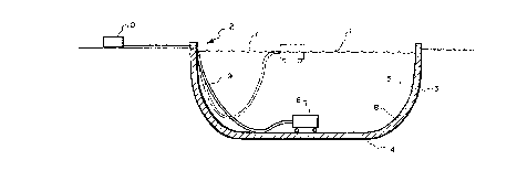
With reference to Figures 1A and 1 B, the present invention is directed to
a method and apparatus for cleaning a water pool 1 contained in an open vessel ~~ 5 defined by a containment wali 3 having bottom 4 and side 5 portions. Embodiments of
the invention utilize a unitary structure or body 6 capable of being immersed in the water
pool 1, for selective operation proximate to the water surface 7 (water surface cleaning
mode) or proximate to the interior wall surface 8 (wall surface cleaning mode).
The unitary body 6 preferably has a hydrodynamically contoured exterior
10 surface for efficient travel through the water. Although bodies 6 in accordance with the
invention can be very differently shaped, it is intended that they be relatively compact in
size fitting within a two foot cube envelope. Figure 1 A depicts a heavier-than-water body
6 which in its quiescent or rest state typically sinks to a position (shown in solid line)
proximate to the bottom portion 4 of the vessel wall 3. In an active state, the body 6 is
1~ lifted to a position (shown in dash line) proximate to the surface 7 of water pool 1.
Alternatively, Figure 1 B depicts a lighter-than-water body 6 which in its quiescent or rest
state rises to proximate to the surface 7 of water pool 1. In an active state, the body 6
is caused to descend to the bottom 4 portion of wall 3. The active state in either Figure
1A or Figure 1 IB is typically produced in accordance with preferred embodiments of the
20 invention by a water flow through flexible hose 9 to or from hydraulic pump 10.
The body 6 is essentially comprised of upper and lower portions, 6U and
6L respectively, spaced in a nominally vertical direc~tion, and front and rear portions, 6F
and 6R respectively, spaced in a nominally horizontal direction. A traction means such
as wheels 11 are typically mounted adjacent the body lower portion 6L for engaging the
2~ wall surface 8.
Embodiments of the invention are based, in part, on a recognition of the
following considerations:
"
CA 02224980 l997- l2- l7
WO 97/01689 PCT/US96/11238
1. Effective water surface cleaning (skimming) reduces the overall task
of swimming pool cleaning since most debris in the water and on the vessel wall surface
previously floated on the water surface.
2. A water cleaner capable of floating or otherwise traveling to the same
5 place that the debris floats can capture debris more effectively than a fixed position built-
in skimmer.
3. A water surface cleaner can operate by using a weir, a water
entrainment device, or by scooping up debris as it moves across the water surface. The
debris can be collected in a water permeable container.
4. A single unitary structure or body can be used to selectively operate
proximate to the water surface in a water surface cleaning mode and proximate to the
wall surface in a wall surface cleaning mode. A common debris collection container can
be used in both modes.
5. The level of the body in the water pool. i.e., proximate to the water
surface or proximate to the wall surface, can be controlled by a level control subsystem
capable of selectively defining either a water surface mode or a wall surface mode. The
mode defined by the subsystem can be selected via a user control, e.g., a manual switch
or valve, or via an event sensor responsive to an event such as the expiration of a time
interval.
6. The movement of the body in the water pool can be controlled by
a propulsion subsystem, preferably operable to selectively propel the body in either a
forward or rearward direction. The direction is preferably selected via an event sensor
which responds to an event such as the expiration of a time interval or an interruption
of the body's motion.
7. A cleaning subsystem can be operated in either a water surface
cleaning mode (e.g., skimming) or a wall surface cleaning mode (e.g., vacuuming or
sweeping).
CA 02224980 1997-12-17
W O 97101689 PCTrUS96/11238
8. The subsystems can be powered from a common source or from
different sources which can include hydraulic (either positive or negative pressure),
pneumatic, and electrical.
Four exemplary embodiments of the invention will be described hereinafter.
5 All of these embodiments will be assumed to utilize a heavier-than-water body which in
a quiescent state rests proximate to the wall bottom and in an active state rises to
proximate to the water surface. The first three embodiments are configured to be driven
from the discharge or positive pressure side of a motor driven hydraulic pump. The
fourth embodiment (Figures 21-27) is configured to be driven from the intake or negative
10 pressure (suction) side of such a pump.
Since the several embodiments have structural, functional, and operational
features in common, several general comments will initially be presented with reference
to Figure 2, followed by a detailed discussion of each embodiment and its related
Figures.
Figure 2 comprises a schematic diagram generally representing the primary
functional aspects of preferred systems in accordance with the invention. The system
of Figure 2 is shown as primarily including a level control subsystem 14 and a propulsion
control subsystem 16. The level control subsystem 14 is comprised of a level mode
controller 14A capable of selectively defining either a first mode (water surface level) or
20 a second mode (wall sur~ace level). The mode defined by controller 14A is determined
by a user input 14B such as a manual switch or by an event sensor 14C in response to
an event such as the expiration of a time interval or the cycling of pump 10. Thus, for
example, in typical operation, the body 6 can be operated in the water surface mode for
a one hour interval and then switched to the wall surface mode for a two hour interval.
25 Alternatively, if the user desires that the body continue to operate in a particular mode,
that mode can be set via user input 14B which overrides the mode toggling normally
produced by event sensor 14C. The mode de~ined by controller 14A controls level
CA 02224980 1997-12-17
W O97/01689 PCTrUS96111238
control element 14D, e.g., a valve, which causes the body 6 to either ascend to
proximate to the water surface or descend to proximate to the wall bottom.
Although embodiments of the invention can be implemented with the body's
rest state being either proximate to the water surface or the wall bottom, the former
5 implementation is presently preferred because when at rest, the body will be
unobtrusively out of the way of swimmers.
Resting at the water surface can be achieved with sufficient buoyancy built
into the body 6 so that it floats at rest, with weight low and buoyancy high so it is stable
(right side up) at both the water surface and at the wall bottom. In order to clean the
10 side and bottom portions of the wall surface, a sufficient hold down force must be
produced to keep the traction means 11 in adequate contact with the wall surface.
Resting on the wall bottom requires that the body 6 sink when it is not
powered. It must have its weight low and buoyancy high so it is stable on the water
surface and beneath it. The body 6 can be moved from the wall bottom to the water
15 surface by producing a vertical force component, e.g., by an appropriately directed water
flow, as will be discussed hereinafter, to push the body to the water surface.
To provide ease of installation and use, and to provide tolerance for the
magnitude of the lifting force and the weight of the body when carrying different amounts
of collected debris, and to aid stability when cleaning the water surface, it is presently
20 preferred that the body lift weight and/or buoyancy out of the water as it rises. The
vertical lifting force is preferably developed in line with the center of gravity of the body
6 at its operating height. It is desirable to position the weight and/or buoyancy that
comes out of the water around and away from the center of gravity so that the body is
stable on the water surface. For economy in production and shipping, the weight can
25 be provided by filling empty weight cavities in the body with water prior to operation.
Such weight cavities can be filled via a tube which permits water to trickle from a
pressurized supply flow into each cavity during operation. A suction or negative
CA 02224980 1997-12-17
WO 97/01689 PCTrUS96/11238
pressure embodiment can use pump suc~ion to draw a trickle of water though a small
hole in the bo~tom of each weight cavity.
Floating the body to the water surface can be accomplished by drawing air
into flotation cavities via a small tube. A suction cleaner can use pump suction to draw
5 the water out of the cavities and pull air in. In order to prevent air from entering the pool
pump, a flexible plastic bag could be placed in each floatation cavity connected to the
air tube. Water would never enter the air tubing or bags. As water is pulled out of the
cavities, air is pulled into the bags; thus, floating the body. A pressure cleaner can use
a pressurized water powered jet pump to draw water out of the cavi'fies and/or pull or
10 pump air into the cavities.
The mode controller 14A, in addition to controlling level control element
14D, also controls cleaning control element 14E. When in the water surface mode,element 14E, e.g., a valve, causes skimming action and may additionaliy allow a whip
hose to sweep the wall surface. When in the wall surface mode, element 14E. preferably
15 causes wall sur~ace vacuuming and/or sweeping. General considerations for wall surface
cleaning can be summarized as follows:
POSITIVE PRESSURE CLEANER
~. The wall surface can be vacuumed using a source of pressurized
20 water to power a liquid/liquid jet pUMp with a nozle, a suction opening in close fluid
communication with the wall surface to be cleaned, a tubular throat section, and a
porous collection means (bag or container) coupled downstream of the throat section
outlet to collect debris; or
2. A jet pump can be used to evacuate a container containing a porous
2~ collection means. having an opening in close fluid communication with the wall surface
to be cleaned; or
_
CA 02224980 l997-l2-l7
WO97/01689 PCTnJS96/11238
3. A travelling body can scoop up debris in its path in a porous
collection means. Scooping performance can be enhanced by water jetted in the
direction of water flow relative to the body.
Water exiting from the body can provide thrust for propulsion and/or
5 holding the device proximate the wall surface to be cleaned.
NEGATIVE PRESSURE CLEANER
1. Pump provided suction can draw water through a porous collection
10 means which may be positioned along the suction hose length in the fixed skimmer, in
the pump inlet, or within the pool cleaner body. The water and debris may pass through
a turbine on its way to the collection means and pump inlet.
2. A suction powered travelling cleaner can scoop up debris in its path
in a porous collection means. Scooping performance can be enhanced by using pump15 suction or pump suction can draw water through a turbine to power a water flow
generating device, such as a pump or propeller to increase the flow of water and debris
through the porous collection means. Water exiting from such a device can provide
thrust for propulsion and/or holding the device proximate to the surface to be cleaned.
In order to provide the traction means 11, e.g, wheels, with sufficient
20 frictional contact with the wall surface to enable the body move with the desired degree
of directional consistency and to keep the sweep hose and/or the inlet to the debris
collection means in close proximity to the wall surface, it is desirable to produce a hold
down force in a nominally vertical direction relative to the body 6 to urge the body, i.e.,
traction means, against the wall surface. This hold down force can be provided by the
25 submerged weight of the body if the vessel floor is relatively flat and the walls are not to
be climbed. Otherwise, water flow away from the body having a sufficient directional
component perpendicular to the wall surface and/or the pressure differential caused by
CA 02224980 l997-l2-l7
W O97101689 PCTAUS96/11238
the surface being in close proximity to the debris path can provide a sufficient hold down
force.
General considerations for water suriace cleaning can be summarized as
foliows:
POSITIVE PRESSURE CLEANER
i. The water surface can be skimmed using a source of pressurized
water to power a liquid/liquid jet pump which draws water and debris on the pool surface
past a weir and a porous collection means; or
2. A source of pressurized water can power a nozle which discharges
a water iet to entrain surface water and debris into a porous collection means; o
3. A travelling body can scoop up debris in its path in a porous
collection means. Scooping performance can be enhanced by entrainment caused by
pressurized water jetted in the direction of water flow through the device.
Water exiting from the body can provide thrust for propulsion or lift.
NEGATIVE PRESSURE CLEANER
1. Pump powered suction can draw water and debris from the water
surface past a weir and a porous collection means; or
2. Pump powered suction can draw water from a chamber with an open
or ciosed top and at least partially open side (at or just below the water surface for
allowing the chamber to remain in fiooded condition essentially up to the pool water
surface as a result of surface water anci debris entering said chamber ) through a porous
debris collection means. The collection means can be in said chamber; or
3. Pump powered s~ction can draw water though a turbine to power
a water flow generating device, such as a pump or propeller, etc., which can propel
surFace water and debris through a porous debris collection means; or
CA 02224980 l997-l2-l7
W O97/01689 PCTrUS96/11238
4. Pump suction can propel a body to allow it to scoop up debris in its
pEh in a porous collection means. Scooping can be enhanced by using pump suctionor pump suction powered flow generating device to increase the flow of water and debris
through the porous collection means.
Water exiting from the body can provide thrust for propulsion or lift.
Figure 2 also shows the propulsion control subsystem 16 which includes
a propulsion state controller 16A capable of selectively defining either a first state
(normal) or a second state (backup). The state of controller 16A is determined usually
by an event sensor 16B which can respond, for example, to the expiration of a time
10 interval or to some other event such as the interruption of body motion. Thus, for
example, in typical operation, the body 6 will operate in the normal propulsion state
being propelled in a forward direction for say two to five minutes, and then will be
switched to the backup state for perhaps 30 seconds, and then will be returned to the
normal state. These timing intervals are preferably separately optimized for each different
15 installation. By periodically switching to the backup state, the possibility of the body
getting stuck behind some obstruction in the vessel is minimized. The normal toggling
of controller 16A can be overridden by a user control 16C.
The controller 16A controls a direction control element 16D,e.g. a valve,
which develops a forward propulsion force during the normal state and a rearward20 propulsion force during the backup state. These forces include force components
nominally horizontally oriented relative to the body 6 to enable the body to be propelled
along the water surface (during the water surface cleaning mode) and along the side and
bottom positions of the wall (during the wall surface cleaning mode).
An optional steering mechanism 16E can be incorporated to vary the
2~ direction of the for~ard and/or rearward propulsion foroe components to better
randomize the body~s travel path. This steering action can include the selective utilization
of side thrust water discharge.
CA 02224980 1997-12-17
W O 97/01689 PCTrUS96/11238
More particularly, on both the water surface and wall surface, the body
should be able to travel forward, rearward, and to the left and to the right. This can be
accomplislled by using contact with l:he pool con~ours to randomly redirect the bod~s
travel. Skewing the thrust direction to the axis of the cleaner can bias the travel path for
5 a particular pool. However, to minimize the possibility of the cleaner getting stuck, e.g..
in a corner, it is desirable that the cleaner periodically go backward. In addition, to
assure complete cleaning coverage, it is preferable to be above to turn to the left and to
the right at predetermined intervals, as for example, by selectively discharging the side
thrust flows.
A timing assembly with a water flow powered turbine driving a gear train
can be designed to provide the desired travel path sequence. A variable flow control irl
the water flow line to the turbine can be adjusted by the user to vary the timing cycle
length, e.g., longer for larger pools, shorter for smaller pools.
In order to alter the body travel direction, the thrust direction must be
changed. One way to do this is to move a rudder and/or a wheel, or a jet nozzle, or the
discharge of a jet pump, or redirecting water flow generated by a pump or a propeller
relative to the axis of the cleaner. Another way to is to have the timing assembly alter
the direction of the thrust by operating a steering valve or valves to create a sequence
of pressurized water discharge through differently directed nozzles and/or jet pumps.
A third steering method can use the output of the timing assembly to
change the directional relationship be~ween the body and the hose supplying pressurized
water or drawing water from the body. If the thrust direction relative to the body remains
fixed, and the supply hose has mass and stiffness, the torque created by the timing
assembly will alter the direction of body travel. In this case, since the hose typically exits
2~ from the body horizontally, the body can rotate less than 360 degrees relative to the
hose in a first direction and then rotate a like amount in the opposite direction. This can
be accomplished by having rotation limits which cause the timing assembly output to
reverse direction when said limits are contacted. The timing assembly output can be
13
CA 02224980 1997-12-17
W O97/01689 PCTrUS96/11238
reversed by changing the turbine flow direction, by shifting gears, or by providin~ water
flow to a second turbine that rotates in the reverse direction.
General considerations regarding propulsion can be summarized as follows:
1. The body 6 can be propelled by various means including: turbine
driven traction means, walking mechanisms, oscillating mechanisms that cause
intermittent water flow, imparting kinetic energy that causes motion, and thrust, which is
a reactive force that moves the body in a direction opposite to the direction that water
exits from the body. All of these propelling means can be powered by either positive or
negative pump produced pressure. Thrust is the presently preferred technique because
10 of its relative simplicity and its applicabilityto both surface and underwater propulsion.
Thrust can also create forces up, down, left, right and back for moving the
device on the wall surface, on the water surface, and from one surface to the other.
POSITIVE PRESSURE CLEANER
1. Pressurized water can be jetted from a nozle as a high velocity low
mass stream to create thrust in the opposite direction. The magnitude of the thrust
produced is a function of the water mass multiplied by its velocity.
2. The pressurized water powered nozzle can be part of a liquid/liquid
jet pump which pumps pool water to create a much larger mass and lower velocity water
20 stream with greater thrust from the same water source.
NEGATIVE PRESSURE CLEANER
Pump suction is used to drive a flow generator to produce thrust. A turbine
driven by water drawn through it by pump suction can drive oars, a swimming
2~ mechanism, a pump, or a propeller which can move a large mass of pool water at low
velocity and which can efficiently produce thrust for a given amount of energy input.
14
CA 02224980 1997-12-17
W O97101689 PCT~US96/llZ38
FIRST EMBODIMENT (Figures 3 - 8)
Attention is now directed to Figures 3 - 8 which depict a first embodiment
100 of the invention designed to be powered from the positive pressure side of a motor
driven hydraulic pump 10 via a hose 9 (Figures 1A, 1B). The embodiment 100 is
5 comprised of a unitary body 102 which is primarily formed of upper and lower molded
sections 102U and 102L. Lower body section 102L supports three parallel axles 104A,
104B, 104C. Traction wheels 106A, 106B, 106C are mounted for free rotation on a~les
104A, 104B, 104C respectively for tangentially engaging interior wall surface 8 (hgures
1A, 1B). The body 102 defines an inlet supply fitting 110 which is coupled to the distal
10 end of supply hose 9. The proximal end of hose g is coupled to the pressure outlet of
pump 10.
The water flow supplied to inlet fitting 110 from pump 10 is distributed to
a pluralit~y of outlets carried by body 102 by tubing 112 (best depicted in hgure 8,
omitted from Figures 3 - 7 for clarity purposes). The plurality of outlets include:
.15 1. forward propulsionthrust jet 114
2. rearward ("backup") propulsion thrust jet 116
3. lift jet 118
4. sweep hose 120
5. timing nozle 122
6. vacuum jet pump nozle 124
7. skimmer jet pump nozles 126
The body 102 is configured to define a collection path 130 for wall surface
debris which extends from a vacuum inlet opening 132 (positioned between wheels 106A
and 1~6B close to the wall surface 8) and a vacuum discharge opening 134 (positioned
25 proximate to the body rear portion 102R below the supply inlet htting 110) The vacuum
jet pump nozle 124 discharges a high velocity flow into the path 130 toward the
discharge opening 134. This action produces a suction at the vacuum inlet opening 132
which draws water and debris from adjacent to wall surface 8 and discharges it through
CA 02224980 1997-12-17
W O97/01689 PCTrUS96/11238
discharge opening 134. The vertical component of the water drawn in through vacuum
inlet opening 132, together with the weight of the unit, creates a hold down force acting
to urge the traction wheels 106 against the wall surface 8.
The body 102 also defines a collection path 136 for surface water and
5 debris. More particularly, the body 102 defines an open skimmer chamber 138 having
an entrance 140 positioned between semi-cylindrical projections 142A,142B. A weir 143
having sides 144A, 144B is mounted adjacent to the entran~e 140 positioned between
the projections 142A, 142B. The weir 143 is mounted for reciprocal vertical motion
relative to the body so that when the body is floating proximate to the water surface,
10 surface water will flow or spill over the weir sides 144A, 144B into the open skimmer
chamber 138. The path 136 extends from the entrance 140, through the chamber 138,
to a discharge opening 146 positioned adjacent to discharge opening 134 proximate to
the body rear portion 102R below the supply inlet fitting 110. The skimmer jet pump
nozles 126 discharges a high velocity flow into path 136 toward the discharge opening
15 146. This action produces a suction which draws water and debris from chamber 138
and discharges it through discharge opening 146.
The open mouth 150 of a debris collection container or bag 152 is
detachably mounted around discharge opening 134 and 146. The bag 152 is preferably
formed of water permeable material for the side and bot~om panels 154 to perrnit the
20 water from the discharge openings 134, 146 to flow through the bag. The top and rear
panels 156,158 are preferably formed of impermeable material to discourage an upward
flow of water out of the bag 152 which would create an unwarlted downward thrust.
Each of the aforementioned projections 142A, 142B is defined by a semi-
cylindrical wall 158, which together with a lid 160, enclo~es a cavity 162. As will be
25 shown hereina~ter, each cavity 162 fills with water to the level of its lid 160. Each lid 160
has an overflow hole 164. The water filled cavities provide ballast for stability near the
water surface. The body can be thrust to the water surfaoe by a downward flow exiting
from the lift jet outlet 118. When the body reaches the ambient air/water surface
16
CA 02224980 1997-12-17
W O 97/01689 PCT~US96/11238
boundary, the weight of water in the two cavities 162 being lifted above the water surface
reaches equilibrium with the thrust produced by je~ 118 to establish an operating level
appropriate for skimming actiorl by weirs 143.
The body lower section 1 02L preferably carries one or more guard wheels
- 5 165 mounted for rotation on a vertical axis for facilitating movement around obstructions.
Particular reference is now called to Figure 8 which schematically depicts
the water flow through the embodiment 100 structurally depicted in Figures 3-7. Note
that water entering the inlet 110 initia31y fills weight cavities 162 and may exi~ through
overflow holes 164. The water entering water inlet 110 is also directed to the
10 aforementioned timing nozle 122, preferably via an adjustable flow control 168 for
driving a turbine 170. The turbine 170 forms part of a timing assembly 171 whichincludes a gear train 172 controlling a steering valve 174. The steering valve 174 can
define either the aforementioned normal propulsion state or back-up propulsion state.
When the steering valve 174 is in the back-up state, water supplied to port 175 is
15 discharged via the rearward propulsion thrust jet 116 to move the body rearwardly.
When the steering valve 174 is in its normal state, the water supplied to port 17~ exits
via forward outlet port 176. The flow from port 176 is supplied to supply port 177 and
control port 178 of an alternating level control valve 179. The valve 179 is capable of
selectively defining either a wall surface cleaning mode, or a water surface cleaning
20 mode. When in the wall surface cleaning mode, the water flow to supply port 177 is
discharged via outlet port 180 to the vacuum jet pump nozle 124, the forward
propulsion thrust jet 114, and the sweep hose outlet 120. The outlet 120 is preferably
connected to an adjustable flow control 181 which supplies one end of a whip or sweep
hose 182. When the level control valve 179 is in the water surface cleaning mode, the
25 water flow supplied from port 177 to valve 179 is directed via outlet port 184 to the lift jet
118 and to a pair of skimmer jet pump nozles 126. Although not represented in ~igure
8. a water flow can also be provided to the sweep hose 182 in the water surface cleaning
CA 02224980 1997-12-17
WO 97/01689 PCT~US96111238
mode to enable the sweep hose 182 to hang below the body 102 and sweep against the
wall surface, e,g, steps.
The initiation of a flow from outlet port 176 to control port 178 is used as
the event to switch the state of level control valve 179. Thus. for example, each time the
5 steering valve 174 initiates a flow out of port 176, it will switch the mode from wall surface
cleaning to water surface cleaning or vice versa. Different events could, of course, be
used to toggle level control valve 179. Additionally, it can be recalled from Figure 2 that
in some installations, it may be desirable to incorporate a user input control for setting
or overriding the event sensor mechanism which normally controls the valve 179 during
10 automatic operation.
In typical automatic operation of the embodiment 100, the body 102 will be
propelled forwardly along the wall surface 8 by the discharge from directionallyadjustable jet 114 for a certain period of time, e.g. two to five minutes. Its direction will
be randomly influenced by the contours of the vessel, the drag of supply hose 9, the
15 influence of sweep hose 182, etc. After a certain interval, the steering valve 174 will
change state and the unit will backup as a consequence of discharge from the rearward
propulsion thrust jet 116. After a further interval, e.g., thirty seconds, the valve 174 will
chang~ state.
20 SECOND EMBODIMENT (Figures 9 -15)
Attention is now directed to Figures 9 - 15 which depict a second
embodiment 200 of the invention designed to be powered from the positive pressure side
of a motor driven hydraulic pump 10 via a hose 9 (Figures 1A, lB). The embodiment
200 is comprised of a unitary body 202 which is primarily formed of upper and lower
25 molded sections 202U and 202L. Lower body section 202L supports three horizontally
oriented parallel axles 204 on which traction wheels 206A, 206B, 206C are mounted for
free rotation for tangentially engaging interior wall surface 8 (Figures 1 A, 1 B). The body
CA 02224980 1997-12-17
W O97/01689 PCTrUS96/11238
202 defines an inlet supply fitting 210 which is coupied to the distal end of supply hose
9. The proxim~l end of hose 9 is coupled to the pressure outlet of pump 10.
The water flow supplied to inlet fitting 210 from pump 10 is distributed to
a plurality of outlets carried by body 202 by tubing 212 (best depicted in Figure 15,
5 omitted from Figures 9 - 14 for clarity purposes). The plurality of outlets include:
1. forward thrust jet 214
2. rearward ("backup") thrust jet 216
3. thrust/lift jet 218
4. sweep hose 220
~. timing nozle ~
6. vacuum jet pump nozle 224
7. surface cleaning nozle 226
8. Ieft jet 228
9. right jet 230
The body 202 is configured to define a collection path 230 for wall surface
debris which extends from a vacuum inlet opening 232 (positioned between wheels 206A
and 206B close to the wall surface 8) and a vacuum discharge opening 234. The
vacuum jet pump nozle 224 discharges a high velocity flow into the path 230 toward the
discharge opening 234. This action produces a suction at the vacuum inlet opening 232
20 which draws water and debris from adjacent to wall surface 8 and discharges it through
discharge opening 234. The vertical component of the water flowing through path 230,
together witl~ the weight of the unit, creates a hold down force acting to urge the traction
wheels 206 against the wall surface 8.
The body 202 also defines a collection path 236 for surface water and
2~ debris. More particularly, the upper body section 202 dehnes a horizontal shelf surface
having upstanding side walls 240A, 240B and a central upstanding fin 242. As the bod
moves forward through the water pool near the surface, surface water and debris are
scooped up moving rearwardly over surface 238 between side walls 240A, 240B. The
19
CA 02224980 1997-12-17
W O97/01689 PCT~US96/11238
collection path 236 extends from the leading edge 243 of surface 238 to a trailing edge
244. The surface 238 defines a cutout 246 below which the aforementioned surfacecleaning nozle 226 is mounted. The nozle 226 discharges a flow through cutout 246
into path 236 toward the trailing edge 244. This action facilitates the flow of water and
debris over surface 238 from the leading to the trailing edge thereof.
Note also that discharge opening 234 of collection path 230 also opens
onto shelf 238 via cutout 248 just upstream from the trailing edge 244.
The open mouth 250 of a debris collection container or bag 252 is
detachably mounted adjacent to trailing edge 244 between upstanding sidewalls 240A,
10 240B. The bag 252 is preferably formed of water permeable material to permit water
flowing rearwardly from the shelf 238 to flow through the bag.
The aforementioned upstanding walls 240A, 240B, as well as central fin 242
each enclose a cavity 262. As will be shown hereinafter, each cavity 262 fills with water
to the level of an overflow hole 264. The water filled cavities provide ballast for stability
15 near the water surface. The body can be thrust to the water surface by a downward flow
exiting from the thrust/lift jet outlet 218. When the body reaches the ambient air/water
surface boundary, the weight of water in the cavities 262 being lifted above the water
surface reaches equilibrium with the thrust produced by jet 218 to establish an operating
level appropriate for skimming action over sheK 238.
The body 202 preferably carries a plurality of guard rollers 265 each
mounted for rotation about a vertical axis. The rollers 265 are distributed around the
periphery 266 of body 202 and facilitate the body's movement around obstructions.
Particular reference is now called to Figure 15 which schematically depicts
the water flow through the embodiment 200 structurally depicted in Figures 8-12. Note
25 that water entering the inlet 210 initially fills weight cavities 262 and is also directed to
the aforementioned timing nozle 222, preferably via an adjustable flow control 268 for
driving a turbine 270. The turbine 270 forms part of a timing assembly 271 whichincludes a gear train 272 controlling a steering valve 274. The steering valve 274 can
CA 02224980 1997-12-17
W O97101689 PCT~US96~11238
define either the aforementioned normal propulsion state or back-up propulsion state.
When the steering valve 274 is in the back-up state, water supplied to port 275 is
discharged via the rearward propulsion thrust jet 216 to move the body rearwardly.
Additionally, water can be selectively discharged through left and right jets 228, 230 to
5 facilitate the body freeing itself from any encountered obstructions. These same side
thrust jets are ~Iso preferably used in the normal propulsion state to better randomize
travel and escape obstructions.
When the steering valve 274 is in its normal state, the water supplied to por~
275 exits via forward outlet port 276. The flow from port 276 is supplied to supply port
10 277 of an alternating level control valve 279.
The valve 279 is capable of selectively defining either a wall surface
cleaning mode, or a water surface cleaning mode. The valve mode is switched
whenever a flow to control port 278 is initiated. As shown in Figure 15, the flow to
control port 278 is derived from sup,ply inlet 210. Accordingly, whenever the pump 10
15 supplying inlet 210 starts up, the mode of valve 279 changes.
Although Figure 15 depicts the initiation of a flow to control port 278 from
inlet 210 as the triggering event to switch the level control valve 279 mode, other events
could, of course, be used to toggle valve 279. Moreover, it should be recalled from
Flgure 2 that it maybe desirable to incorporate a user input control for setting or
20 ove, . i.lil Ig the event sensor which normally controls the automatic operation of valve 279.
When in the wall surfac:e cleaning mode, the water flow to supply port 277
is discharged via outlet port 280 to the vacuum jet pump nozle 224, the forward
propulsion thrust jet 214 (preferably directionally adjustable), and the sweep hose outlet
220. An adjustable flow control 281 is preferably connected just upstream of the sweep
25 hose outlet 220. When the level con~rol valve 279 is in the water surface cleaning mode,
the water flow supplied from port 277 to valve 279 is directed via outlet port 284 to the
thrusttlift jet 218 and to the aforementioned surface cleaning nozle 226. Although not
represented in Figure 8, a water flow can also be provided to the sweep hose 220 in the
- 21
CA 02224980 1997-12-17
W O 97/01689 PCT~US96/11238
water surface cleaning mode to enable the sweep hose outlet to hang below the body
202 to sweep against portions of the wall surface.
In typical automatic operation of the embodiment 200, the body 202 will be
propelled along the wall surface 8 by the discharge from thrust jet 214 for a certain
5 period of time, e.g., two to five minutes. Its direction will be randomly influenced by the
contours of the vessel, the drag of supply hose 9, the influence of sweep hose 282, etc.
When the timing assembly changes the steering valve 274 state, the unit will backup as
a consequence of discharge from the rearward propulsion thrust jet 216 for a certain
interval, e.g., thirty seconds, before resuming its normal state. As represented in Figure
15I the alternating valve 279 will periodically switch modes independently of timing
assembly 271 in response to a triggering event such as the cycling of pump 10.
The following Table I list the primary characteristics of a typical unit
corresponding to embodiment 200:
Types of pools cleaned: All inground and above ground pools
Power source: Booster pump and/or pool pump
Wheels - number / diameter: 3 wheels / 4" diameter
Debris collected in: Mesh bag
Wall Cleaning: Vacuum & sweeps
Vacuum jets:
Vacuum minimum diameter: 2"
Vacuum opening width 7.1"
Sweeping: Whip hose
Propulsion: 1 thrust jet
Wall surface travel path: Forward and left, straight, right, straight and
random. Back and up to the left and right.
Water surface cleaning? Skims
Surface cleaning iets:
Opening width: 9.5"
CA 02224980 1997-12-17
WO 97/01689 PCTrUS96/11238
Debris collection bag opening: 3" high x 5" wide
Propulsion: 1 thrust/lift jet
Water surface travel path: Forward and ieft, straight, right, straight and
random. Back and down to the left and right
~ 5
THIRD EMBODIMENT (Figures 16 - 20)
Attention is now directed to Figures 16 - 20 which depict a third
embodiment 300 of the invention designed to be powered from the positive pressure side
of a motor drive hydraulic pump 10 via a hose 9 (Figures 1 A, 1 B). The embodiment 300
10 is comprised of a unitary body 302 supported on three traction wheels 306A, 306B, 306C
mounted for free rotation on horizontal axies for tangentially engaging interior wall
surface 8. The traction wheels are arranged to essentially orient the nose or front 302F
of the body down about 15 degrees relative to the rear 302R of the body, as shown in
Figure 16.
The body 302 is provided with an inlet supply fitting 310 which is coupled
to the distal end of supply hose 9. The proximal end of hose 9 is coupled to pressure
outlet of pump 10.
The water flow supplied to inlet fitting 310 from pump t0 is distributed to
a plurality of outlets carried by body 302 by tubing 312 (best depicted in figure 20,
20 omitted from figures 16 - t9 for clari~y purposes). The plurality of outlets include:
1. forward propulsion thrust/surface cleaning jets 314
2. rearward ("backup") thrust jet 316
3. lift jet 318
4. sweep hose 320
5. timing nozle 322
6. vacuum jet pump nozle 324
7. left jet 326
8. right jet 328
23
CA 02224980 1997-12-17
W 097tO1689 PCT~US96/11238
The body 302 is configured to dehne a collection path 330 for wall surface
debris which extends from a vacuum inlet opening 332 (positioned between wheels 306A
and 306B close to the wall surface 8), and a vacuum discharge opening 334. The
vacuum jet pump nozle 324 discharges a high velocity flow into the path 330 toward the
5 discharge opening 334. This action produces a suction at the vacuum inlet opening 332
which draws water and debris from adjacent to wall surface 8 and discharges it through
discharge opening 334. The vertical component of the water flow through path 330,
together with the weight of the unit, creates a hold down force acting to urge the traction
wheels 306 against the wall surface 8.
The body 302 also defines a collection path 336 for surface water and
debris. More particularly, the body 302 defines a horizontal shelf surface 338 having
upstanding side walls 340A, 340B. As the body moves forward through the water pool
near the water surface, surface water and debris are scooped up moving rearwardly over
surface 338 between side walls 340A and 340B. The collection path 336 extends from
15 the leading edge 343 of surface 338 to a trailing edge 344. The surface 338 defines a
cutout 348 aligned with the aforementioned discharge opening 334, just upstream from
the shelf trailing edge 344.
The open mouth 350 of a debris collection container or bag 352 is
detachably mounted to the body 302 proximate to the trailing edge 344 and spaced20 above the surface 338 as is best depicted in FigtJre 16. The bag 352 is preferably
formed of water permeable material to perrnit water flow therethrough.
The aforementioned upstanding walls 340A, 340B, each enclose a cavity
362. As would be shown hereinafter, each cavity 362 hlls with water to the level of an
overflow hole 364. The water filled cavities provide ballast stability when the body is at
25 the water surface. The body can be thrust to the water surface by a downward flow
exiting from lift jet 318. The jet 318 is able to lift the body to a level where the weight of
water in the cavities 362 being lifted above the water surface reaches equilibrium with the
thrust afforded by jet 318.
24
CA 02224980 1997-12-17
W O 97/01689 PCT~US96/11238
The body 303 preferably carries a plurally of guard rollers 365 each
mounted for rotation about a vertical axis. The rollers 365 are distributed around the
periphery 366 of body 3û2 and facilitate the bod~s movement around obstructions.
Particular reference is now called to hgure 20 which schematically depicts
water flow to the embodiment 300 structurally depicted in Figures 16 - 19. Note that the
water entering the water inlet 310 initially fills weight cavities 362 and is also directed to
the aforementioned timing nozle 327, preferably via an adjustable flow control 368 for
driving a turbine 370. The turbine 370 forms part of a timing assembly 371 which10 includes a gear train 372 controlling a steering valve 374 which can define either a
normal propulsion state or a backup propulsion state. When the backup state is defined,
water supplied to port 375 is discharged via the rearward propulsion thrust jet 316 to
move the body rearwardly and/or to left and right jets 326, 328 to produce side thrust for
freeing the body from any encountered obstructions. These same side thrust jets are
15 also preferably used in the normal propulsion state to better randomize travel and escape
obstructions.
When the steering valve 374 is in its normal state, the water supplied to port
375 exits via forward outlet port 376. The flow from port 376 is supplied to supply polt
20 377 of an alternating level control valve 379. The valve 379 is capable of selectively
defining either a wall sur~ace cleaning mode or a water surface cleaning mode. Valve
mode is switched when ever a flow to control port 378 is initiated. As shown in Figure
20, the flow ~o control port 378 is derived from supply inlet 310. Accordingly, whenever
the pump 10 starts up, the mode of vah/e 379 is changed.
Although Figure 20 depicts the initiation of a flow to control port 378 frorn
inlet 310 as l:he triggering event to switch t'ne control valve 379 mode, other events could,
of course, be used to toggle valve 379. Moreover, it should be recalled from Figure 2
CA 02224980 l997-l2-l7
W O97/~1689 PCTrUS96/11238
that it is appropriate to incorporate an input control for enabling a user to set or override
the normal control of valve 379.
Note in Figure 20 that water is supplied to the thrust/surface cleaning jets
314 during the normal state of the steering valves 375 regardless of the mode defined
5 by alternating valve 379. Thus, when the system is in the wall surface cleaning mode,
the body is forwardly propelled bythe thrust/surface cleaning jets 314 and a component
of the vacuuming jet pump 324. During the wall surface cleaning mode the body will be
oriented nose down as shown in Figure 16. The bottom of the collection bag 352 is
located above the shelf surface 338 (Figure 16) and, therefore, most of the water
10 discharged from the thrust/surface cleaning jets 314 clings to the surface 338 and is
discharged without passing through the collection bag. This results in greater propulsion
and hold down thrust from these jets 314 then if the water were to pass through the bag
material and debris therein. As the body 302 traverses the wall surface, debris is
collected in the bag as a consequence of the action of vacuum jet pump nozle 324.
15 Further wall surface cleaning occurs as a consequence of the sweeping action of whip
hose 382.
When the valve 379 defines the water surface cleaning, the lift jet 318
thrusts the body to the water surface to an equilibrium level at which the weight of the
body, including the water filled cavities 362, above the water surface equals the vertical
20 force component of lift jet 318. When at the water surface, the body assumes a more
horizontal attitude so that as it moves forward along the water surface, water and floating
debris will flow into the bag 352 above surface 338.
In typical automatic operation of the embodiment 300, the body 302 moves
forward for two to five minutes cleaning either the wall surface or the water surface with
25 its direction randomly influenced by objects it encounters and by water periodically jetted
out of the left jet for about 30 seconds, and subsequently out of the right jet for about
30 seconds. Intervals of straight travel occur before, between, and after the side thrust
intervals. For example, each two to five minutes the body 302 can be caused to move
26
CA 02224980 1997-12-17
W O97/01689 PCT~US96/11238
rearwardly for about 30 seconds by discharging a flow through the backup thrust jet 316,
which can optionally occur in conjunction with one of the side thrusts jets 326, 328. For
example, the timing assembly steering valve can be programmed to provide three
periods of alternating side thrusts during each major cycle with the side thrust during
5 sequential backup intervals alternating.
As depicted in Figure 16, the lift jet 318 optionally be configured as a jet
pump 318J to increase water flow, thrust and efficiency. Similarly, a jet pump could also
be substituted for any of the other aforementioned jets, such as right jet pump 328J
(Figure 17).
FOURTH EMBODIMENT (Figures 21 -27)
Attention is now directed to Figures 21 - 27 which depict a four~h
embodiment 400 of the invention designed to be powered from the negative pressure
(suction) side of a motor driven hydraulic pump 10 via a hose 9 (Figures 1A, 1B) which
15 hose is preferably specially configured as is depicted in Figure 23. The embodiment 400
is comprised of a unitary body 402 which is primarily formed of upper and lower molded
sections 402U and 402L. Lower body section 4~2L supports three traction wheels 406A,
406B, 406C mounted for free rotation on horizontal axles for tangentially engaging interior
wall surface 8. As shown in Figure 23, the traction wheels are arranged on the body so
20 that when resting on a horizontal surface, the nose or front 402F of the body will be
inclined downwardly from the rear 402R of the body by about 18 degrees. The body 402
is provided with an outlet supply fi~ting 410 u/hich is mounted in the free end of swivel
arm 411 and coupled to the distal end of supply hose 9. The proximal end of hose 9 is
coupled to the suction side of pump 10. The pump suction applied to fitting 410 is
25 coupled via arm 411 to various inlets in the body 402 including:
1. vacuuming inlet 420
2. timing assembly timing inlet 422
3. alternating valve inlet 424
CA 02224980 l997-l2-l7
W O 97/01689 PCT~US96/11238
As will be seen hereinafter, pump suction is able to pull water in through these inlets for
flow through outlet fitting 410 to the pump 10 suction side.
The upper body section 402U is comprised primarily of a horizontally
oriented surface 438 having a pair of upstanding side walls 440A and 440B. The surface
5 438 defines a leading edge 443 and a trailing edge 444. The open mouth 450 of a water
surface debris collection container or bag 452 is detachably mounted to the body 402
behind the leading edge 443 above the surface 438. The bag 452 is preferably formed
of water permeable material to permit water flow therethrough.
The aforementioned upstanding walls 440A, 440B, each enclose a cavity
10 462 containing flaccid plastic bag 464. An air tube 466 communicates with the flaccid
bag 464 and extends through hose 9 as depicted in Figure 23 to atmospheric air above
the water surface, e.g., in the pools built-in wall skimmer (not shown). The water cavity
462 communicates with a tube 468 which is connected to the inlet port 424 of an
alternating valve 470. As is shown in Figure 27, the outlet side of the alternating valve
15 470 is connected via a port 472 to the suction outlet fitting 410. Additionally, the
alternating valve control port is similarly connected to suction fitting 410.
The aforementioned vacuum inlet 420 shown in Figure 23 opens into a
vacuuming path 476 which includes a turbine 478. The vacuuming path 476 discharges
into the suction outlet fitting 410 via swivel arm 411. Thus, when water is pulled in
20 through the vacuuming inlet 420 by the pump suction applied to fitting 410, it will move
past and drive turbine 478. A thrust propeller 480 is mounted to the shaft of turbine 478
for propelling the body along either the wall surfaoe or on the water surface.
The water inlet 422 drives a turbine 482 which is coupled to a steering gear
train 484 of a timing assembly 485. This gear train is coupled to the hub 486 of swivel
25 arm 411 for rotating the hub arm around post 487.
The alternating valve 470 is capable of toggling between a water surface
cleaning mode and a wall surface cleaning mode. Switching of the alternating valve
mode is in response to the initiation of flow through the control port 474. Port 474 is
-
CA 02224980 l997-l2-l7
W O97/01689 PCT~US96/11238
coupled via fitting 410 to pump su~tion via hose 9 and thus in the configuration shown,
the valve 470 mode changes whenever the pump starts up.
For water surface cleaning, the alternating valve 470 directs the suction
available a~ fitting 410 to draw water out of the cavities 462. This permits the plastic bag
- ~ 464 within each cavity to pull air in via tube 466 which, as has been noted, is routed
through supply hose 9 to atmospheric air. As the bags 464 fill with air, the buoyancy of
the body increases and causes the body to float to the water surface with great stability.
As the propeller 480 propels the body forward, water and floating debris are scooped
from the water surface above shelf surface 438 and guided into the permeable collection
10 bag 452 via the open mouth 4~0.
When the mode of alternating valve 470 changes to the wall surface
cleaning mode, it will stop drawins water out of the cavities 462 and allow water to flow
into the cavities causing the internal bags 464 to collapse and pushing the air therein out
through the tube 466. This action causes the body to lose buoyancy and sink to the
15 pool bottom for operation in the wall surface cleaning mode. In the wall surface cieaning
mode, the body will be propelled along the wall surface by the action of propeller 480
driven by turbine 478. The turbine 478 is driven by the flow of water drawn intovacuuming inlet 420 as a consequence of the suction applied to path 476 via fitting 410.
Debris drawn into the vacuuming inlet 420 during the wall surface cleaning mode will be
20 carried through to the pool filter or can be collected by an inline collection container
located somewhere along the length of supply hose 9 or in the conventional built in wall
skimmer.
In normal automatic operation, the body 402 is propelled forwardly by
propeller 48 in both the wall surface cleaning mode and the water surface cleaning
25 mode. The direction of movement of the body will be randomly influenced by that which
it encounters and by the rotation of the body relative to the swivel arm 411. The arm 411
is reciprocally rotationally driven around post 487 by the action of the steering gear train
484. Preferably, the arm 411 can rotate approximately 270 degrees in one direction over
29
CA 02224980 1997-12-17
W O 97/01689 PCTrUS96/11238
a one to four minute interval. The arm then is driven in the opposite direction for a
similar period. The two states of directional rotation, i.e., clockwise and counter-
clockwise are controlled by the timing assembly 485.
The following Table ll lists the primary characteristics of a typical unit
corresponding to embodiment 400:
Types of pools Cleaned: All Inground and Aboveground Pools
Power source: Pool Pump
Wheels - number / diameter: 3 wheels / 4" diameter
Wall cleaning: Vacuum and sweep
Vacuum minimum diameter: 1 3/8"
Vacuum opening width: ~'
Debris collected in: Inline container
Propulsion: Turbine driven propeller
Wall surface travel path: 270 degrees clockwise & 270 degrees
counterclockwise with pauses as desired
Water surface cleaning: Skims
Debris collected in: Mesh bag
Debris collection bag opening: 3" high x 8" wide
Propulsion: Turbine driving a propeller
Lift: Air from above water in skimmer box
Wall surface travel path: Same as on pool bottom
From the foregoing, it should now be appreciated that a method and apparatus
has been disclosed for automatically cleaning a water pool characterized by the use of
25 a unitary body structure which travels between the wall surface and water surface. The
body structure is preferably compactly dimensioned, i.e., within a 2' x 2' x 2' envelope,
and has hydrodynamically shaped exterior surfaces, which can in part be defined by fins
or wings, enabling it to move efficiently through the water. More particularly, the body's
CA 02224980 l997-l2-l7
W O97101689 PCTrUS96/11238
exterior contour is preferably shaped to facilitate its travel underwater adjacent to the wall
surface, its travel from the wall surface to the water surface, its travel from the wall
surface to the water surface, and its travel along the water surface. For this purpose, the
body exterior can be contoured so that (1) its travel along the wall surface produces a
hold down force component urgin~ its traction means more tightly against the wall
surface, (2) its travel proximate to the water surface produces a lift force component to
help maintain the body at the water surface and (3) its travel between the wall surface
and water surface generates forces appropriate to maintaining the correct attitude of the
body and efficiently employing the source energy.
Although the present invention has been described in detail with reference
only to a few specific embodiments, those of ordinary skill in the art will readily
appreciate that various modifications can be made without departing from the spirit and
the scope of the invention.