Note: Descriptions are shown in the official language in which they were submitted.
CA 02224986 2003-02-21
~" ~ ,
WO 96/17199 PCT/US95115302
JOINT ASSEMBLY AND BACKING MECHANISM THEREFOR
BackgLound
This invention relates to joint assemblies and backing mechanisms therefor,
particularly
to joint assemblies employing backing mechanisms in joints formed by a gasket
disposed
adjacent a flange of a pipe section, the backing mechanism providing for
maintaining a seal
along the inner periphery of the flange.
In pulp and paper mills, chemical plants, integrated circuit fabrication
installations and
other industrial facilities, pipe systems generally are employed to convey
fluids and fluid-like
mixtures. These pipe systems typically include joint assemblies that use pipe
sections having
flanges disposed at the ends thereof, thereby providing for assembling the
sections at joints.
The joint assemblies also typically use gaskets or other sealing materials
adjacent the flanges
so as to form seals in the joints, the seals containing the fluids or fluid-
like mixtures within the
pipe system.
As is commonly understood in the art, a seal is formed by properly seating the
gasket
in the joint. Seating of the gasket is generally effected by applying a load
to the joint so as to
compress the gasket against the flange sufficiently to withstand the pressure
of the conveyed
fluid or fluid-like mixture. In some conventional joint assemblies, a gasket
is seated using a
backing ring dimensioned to fit about a flange. The backing ring is drawn
against the flange so
as, in turn, to draw the flange against the gasket. To do so, conventional
backing rings
generally employ bolts inserted through apertures in the ring, the apertures
being disposed at
locations displaced laterally from the inside periphery of the joint. Thence,
by tightening the
bolts, a laterally-displaced load is applied to the backing ring and a
compressive load is applied
by the backing ring to the joint.
These conventional joint assemblies, however, are subject to significant
problems,
particularly as to proper seating of the gasket along the joint's inside
periphery. Proper seating
can be impeded in such assemblies whenever the effective load along the inside
periphery of
the joint is diminished relative to the load applied to the joint by the
backing ring. A
diminished effective load can be attributed to load losses associated with
deformation of the
flange remote from the joint's inside periphery, as well as to reactive loads
applied adjacent
that periphery but in direction opposite to the compressive load .
CA 02224986 2003-02-21
WO 96117199 I'~ ~ PCT/US95115302
2
Load losses and reactive loads, in turn, can be attributed to the laterally-
displaced
load applied to the backing ring. In particular, once the backing ring is
drawn in contact with
the flange, the laterally-displaced load causes the backing ring to pivot
against the outside
edge of the flange, so as to engage the flange and apply the load only along
that outside edge.
As a result, the flange deforms adjacent that outside edge, generally
consuming some portion
of the applied load. An additional result is the production of a bending
moment along the
flange, whereby the load applied along the outside edge produces a reactive
load directed
away from the gasket adjacent the inside periphery of the joint. Indeed, under
high loading,
the flange may bow sufficiently to pull away from the gasket adjacent the
joint's inside
periphery.
When the effective loading is inadequate to seat the gasket properly, the
fluids and
fluid-like materials conveyed through the pipe system may pass into the joint
between the
flange and the gasket. In that event, those materials can leak from the joint
into the
environment. Any such leakage is highly undesirable both as being broadly
antithetical to
proper performance of a joint assembly, and also as a potential violation of
laws regulating
environmental releases, particularly where the leaked materials are deemed
hazardous.
In addition to leakage, another problem associated with inadequate loading can
be the
trapping in the joint of the fluids and fluid-like mixtures that pass into the
joint. Trapped
materials, for example, may accelerate the degradation of the joint, causing
premature failure.
Trapped materials may also frustrate manufacturing efforts. For example, in
the fabrication of
integrated circuits, high cleanliness and purity standards must be maintained
in order to
maintain satisfactory production yields. Nevertheless, relatively contaminated
materials
generally are used during preparation pressure testing of the pipe system; in
particular, test
water is used to test the integrity of pipe systems at pressures elevated
relative to operating
pressures. Once the pipe system is put in operation, an anomalous disturbance
in the pipe
system, e.g., a pressure transient such as water hammer, can cause test water
trapped in the
system's joints to be released, such release having the potential to
substantially depress yields.
Conventional joint assemblies have not heretofore fully recognized or
adequately
overcome the above problems. Rogers U.S. Patent No. 3,387,867, for example,
proposes a
joint assembly that employs a backing ring having an annular bead, together
with a gasket
having an annular seal-portion of substantially circular cross-section, the
bead and seal-portion
CA 02224986 1997-12-17
WO 96/17199 PCT/LJS95115302
forming a line interposed between the common outside diameter of the pipe
sections and the
outside periphery of a flange. Rogers proposes that a compressive load can be
applied
through the bead along the above-described line when the backing ring is
tightened, so as to
compress the seal-portion against a flange while the bending moment exerted on
the flange is
reduced or eliminated. However, even if that object is accomplished, Rogers is
limited to
joints having seals displaced laterally from the inner periphery of the
respective flange. That
is, Rogers fails to address or overcome the problem of directing and
maintaining compressive
loading adequate to seat properly a gasket or other sealing material along the
inner periphery
of the flange.
Accordingly, there is a need for an improved joint assembly that fully
addresses and
adequately overcomes the above problems of conventional joint assemblies which
employ a
backing ring and gasket. There is also a need for an improved backing
mechanism for use in
such joint assemblies.
The present invention fulfills the aforementioned need for an improved joint
assembly
overcomes the shortcomings of conventional joint assemblies and has advantages
not
heretofore available in such joint assemblies, by providing a joint assembly
employing a
backing mechanism in joints formed by a gasket disposed adjacent a flange of a
pipe section,
the backing mechanism providing for maintaining a seal along the inner
periphery of the
flange. The present invention also fulfills the need for an improved backing
mechanism for use
in such joint assemblies by providing a backing mechanism that can so maintain
a seal adjacent
along the inner periphery of a flange in a joint assembly.
In the joint assembly, a flange is disposed at the end of a pipe section,
sealing material
is disposed adjacent a joint surface of the flange, and a backing mechanism
engages the
flange, the backing mechanism receiving a compressive load and directing that
load so as to
maintain the seating of the sealing material adjacent and along the inside
periphery of a joint
portion formed by the flange and the sealing material.
The inside periphery of the joint portion is disposed substantially adjacent
and along
the inner periphery of the joint surface of the flange, which in turn is
disposed laterally from
the outside surface of the pipe section towards the central axis of the joint.
In one preferred
CA 02224986 1997-12-17
WO 96/17199 PCT/US95115302
4
embodiment, the backing mechanism comprises a backing member that receives the
compressive load and a directing mechanism engaging the backing ring so as to
selectively
direct the compressive load toward the inside periphery of the joint portion.
The directing
mechanism can have various embodiments, including: (i) a rounded surface, the
rounded
surface having selected curvature or curvatures, and being provided in one
case by a collar
having a rounded cross-section, the collar disposed between the backing member
and a load
surface of the flange; and, in another case, by the load surface of the
flange, for instance, by a
beaded portion thereon; (ii) a beveled washer, such as a spring washer, the
washer being
disposed between the backing member and the load surface of the flange; (iii)
a canted surface,
the canted surface being disposed at a selected angle relative to the central
axis of the joint
assembly, and being provided, in one case, by a collar having a substantially
triangular cross-
section and which is disposed between the backing member and the load surface
of the flange
and, in another case, by the load surface of the flange; or (iv) a combination
of the above. The
backing member preferably has a substantially planar surface, a rounded
surface or a rounded
bead by which the backing member engages the directing mechanism.
In a preferred embodiment, the backing mechanism comprises a backing member
having a top face, a bottom face, an inside face and an outside face, the
backing member
receiving a compressive load along the top face and directing the compressive
load to the joint
from the bottom face, the bottom and inside faces meeting in a radiused
portion adjacent the
load surface of the flange and the outside surface of the pipe section, and
the bottom face
having a beveled portion extending from the radius portion toward the outside
face of the
backing member, the beveled portion having a predetermined bevel angle. In
this embodiment,
the beveled portion is drawn to within a predetermined clearance of the load
surface of the
flange by application to the backing member of a compressive load having a
predetermined
value, thereby optimizing the application of the compressive load to the joint
by minimizing or
eliminating deformation of the flange and reactive loading of the joint.
Accordingly, it is a principle object of the present invention to provide a
novel and
improved joint assembly.
It is another principle object of the present invention to provide a novel and
improved
backing mechanism.
CA 02224986 1997-12-17
WO 96/17199 PGT/US95/15302
it is a further object of the present invention to provide a backing mechanism
for use in
a joint assembly employing a gasket, wherein the backing mechanism provides
for maintaining
a seal disposed laterally from the outside surface of a pipe section toward
the central axis of
the joint.
It is yet another object of the present invention to provide a backing
mechanism that
receives compressive loading and selectively directs that loading toward the
inside periphery
of a joint, across a broad loading range.
It is yet a further object of the present invention to provide a backing
mechanism that
maintains a compressive load adjacent and along the inside periphery of a
joint by substantially
precluding application of reactive loads adjacent and opposite to the loading
along that
periphery.
It is yet another object of the present invention to provide a joint assembly
that
optinuzes the application of compressive loading adjacent and along the inside
periphery of the
joint, the periphery being substantially adjacent the inside surface of a
pipe.
'fhe foregoing and other objects, features and advantages of the invention
will be more
readily understood upon consideration of the following detailed description of
the invention,
taken in conjunction with the accompanying drawings.
Brief Description of the Drawinss
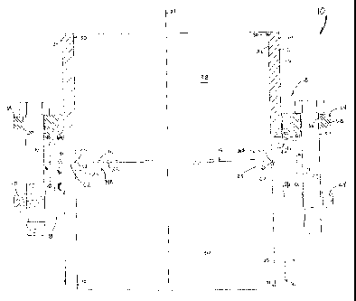
Figure 1 is a cross-sectional view of a conventional joint assembly employing
a
standard backing ring.
Figure 2 is a cross-sectional view of a preferred embodiment of a joint
assembly
employing a backing mechanism according to the present invention.
Figure 3 is a cross-sectional view of another preferred embodiment of a joint
assembly
employing a backing mechanism according to the present invention.
Figure 4 is a cross-sectional view of another preferred embodiment of a joint
assembly
employing a backing mechanism according to the present invention.
Figure 5 is a cross-sectional view of another preferred embodiment of a joint
assembly
employing a backing mechanism according to the present invention.
Figure 6 is a cross-sectional view of another preferred embodiment of a joint
assembly
employing a backing mechanism according to the present invention.
CA 02224986 1997-12-17
WO 96/17199 PCT/US95/15302
6
Refernng to Figures 2-6, various embodiments of a joint assembly 10 according
to the
present invention include a first pipe section 12, a second pipe section 14,
sealing material 16,
backing mechanisms 18 and fasteners 20. The joint assembly 10 also has a
central axis 21
Generally, the joint assembly 10 forms a joint 23 by connecting the first pipe
section 12 and
the second pipe section 14, with the sealing material 16 disposed
therebetween, and applying a
compressive load, designated by the legend LR in Figure 2, to the joint 23
using the backing
mechanisms 18 and the fasteners 20 so as to seat the sealing material 16 in
the joint 23.
The first and second pipe sections 12 and 14 have respective side surfaces 22
and 24
and outside surfaces 26 and 28. The inside and outside surfaces 22, 24, 26 and
28 typically
are annular, in which case they are characterized by respective inside
diameters 30 and 32 and
outside diameters 34 and 36. It is to be recognized, however, that the
surfaces of the pipe
sections 12 and 14 may be other than annular and, even if annular, may have
inside diameters
30 and 32 that are not equal and outside diameters 34 and 36 that are not
equal, all without
departing from the principles of the invention. In any case, the inside
surfaces 24 and 26 of
the pipe sections 12 and 14 define passageways 38 and 40 in those sections for
conveying fluid
and fluid-like mixtures therethrough.
The first and second pipe sections 12 and 14 have respective flanges 42 and 44
disposed at the adjacent ends thereof, the flanges 42 and 44 extending
radially from the central
axis 21 of the joint assembly 10. Each flange 42 and 44 preferably defines
respective outlets
39A and 39B of the respective pipe sections 12 and 14. Each flange 42 and 44
preferably is
integral with and extends continuously and fully around of the respective pipe
section 12 and
14. However, it is to be recognized that either flange 42 or 44, or both, may
be other than
integral and may not so extend, without departing from the principles of the
invention.
Each flange 42 and 44 has a joint surface 46 and a load surface 48. Each joint
surface
46 has an inner periphery 50 disposed laterally from the outside surface 26 or
28 of the
respective pipe section 12 or 14 toward the central axis 21 of the joint
assembly 10. Each load
surface 48 of the flanges 42 and 44 generally is substantially perpendicular
to the central axis
21 of the joint assembly 10. However, as described hereinafter, the load
surface 48 may be
canted at a selected angle relative to the central axis 21 of the joint
assembly 10. Moreover,
CA 02224986 1997-12-17
WO 96!r7199 PG"T/US95/15302
7
the load surface 48 may have selected curvature or curvatures, including being
convex or
concave.
In the joint assembly 10, the sealing material 16 is disposed adjacent the
joint surface
46 of the flanges 42 and 44. The sealing material 16, typically a gasket, may
be any of a
S variety of materials, and may take a variety of forms, without departing
from the principles of
the invention. Preferably, the sealing material 16 has an inner periphery 52
that is dimensioned
to coincide substantially with the inner periphery 50 of the joint surface 46
of the flanges 42
and 44. Where the pipe sections R2 and 14 and the flanges 42 and 44 are
annular, the sealing
material 52 preferably also is annular. It is to be recognized, however, that
the sealing
material may have other shapes and may have other dimensions, without
departing from the
principles of the invention, provided the shape of the sealing material 16 is
appropriate to
sealing the joint 23 of the joint assembly 10.
The fasteners 20 preferably comprise a plurality of bolts 54 spaced about the
joint
assembly 10 at substantially regular intervals. As shown in Figures 2-6, the
bolts 54 are
coupled to the backing mechanisms 18 by insertion in apertures 56 disposed in
the mechanisms
18. It is to be recognized, however, that the fasteners 20 may be other than
bolts 54 and may
be coupled to the backing mechanisms 18 other than through use of apertures 56
without
departing from the principles of the invention. The important point is that
the fasteners 20 are
associated with the backing mechanisms 18 so as to apply the compressive load
to such
mechanism 18.
l;ach backing mechanism 18 comprises a backing member 58 and directing
mechanism
60. The backing member 58 receives the compressive load from the fasteners 20.
The
directing mechanism 60 engages the backing member 58 so as to direct the
compressive load
to the joint 23 and, thereby, seat the sealing material 16 in the joint.
Preferably, the directing
mechanism 60 selectively directs the compressive load toward the inner
periphery 50 of the
joint surface 46 of a flange 42 or 4~4 so as to seat the sealing material 16
in the joint 23,
including adjacent the inside periphery 62 of the joint 23, the inside
periphery 62 being
disposed adjacent and along the inner periphery 50 of the joint surface 46 of
a flange 42 or 44.
Depending on the compressive load applied to the backing mechanisms 18, the
inside
periphery 62 may obtain various dispositions, for example, the variations may
range from
coincidence with the inner periphery 50 outwardly to coincidence with a line
formed parallel to
CA 02224986 1997-12-17
WO 96/17199 PGT/US95/15302
8
the central axis 21 and passing through a flange 42 or 44 at the point at
which the directing
mechanism 60 applies the compressive load. It is to be recognized, however,
that
notwithstanding the direction of the compressive load as selected by the
directing mechanism
60, the sealing material 16 preferably seals the joint 23 so that the fluids
or fluid-like mixtures
conveyed through the passageways 38 and 40 do not pass into the joint 23.
In operation, the fasteners 20 engage the backing member 58 so as to apply a
compressive load thereto and, thereby, draw the backing ring 58 against the
associated
directing mechanism 60 in a direction substantially parallel to the central
axis 21 of the joint
assembly 10. The directing mechanism 60 directs that compressive load to the
joint 23 so as
to compress the sealing material 16 against one or both flanges 42 or 44 and,
thereby, seats
the sealing material 16 in the joint 23. By selectively directing that
compressive load, the
directing mechanism 60 substantially precludes both the occurrence of load
losses in, and the
application of reactive loads adjacent and opposite to, the compressive
loading necessary to
properly seat the sealing material 16. In so operating, the backing member 58
and associated
directing mechanism 60 of one pipe section 12 or 14 preferably cooperate with
another
backing member 58 and directing mechanism 60 ofthe other pipe section 14 or
12, it being
recognized that such cooperation may be absent without departing from the
principles of the
invention.
Refernng to Figure 2, a preferred embodiment of the joint assembly 10
according to
the present invention includes a backing member 58 in the form of a backing
ring 64, and a
directing mechanism 60 in the form of a collar 66 having a rounded cross-
section, the collar 66
being disposed between the backing ring 64 and the load surface 48 of a
respective flange 42
or 44. Although the collar's cross-section, as shown, is substantially
circular, it is to be
recognized that other cross-sectional shapes may be used without departing
from the
principles of the invention, provided they operate to direct the compressive
load as described
herein. The backing ring 64 has a substantially planar surface 68, along which
it engages the
collar 66. Preferably the planar surface 68 at its extremities is rounded so
as to prolong the
useful life of the backing mechanism 18 and, thence, the joint assembly 10. It
is to be
recognized, however, that the backing ring 64 may have other than rounded
extremities
without departing from the principles of the invention. It is also to be
recognized that the
collar 66 may be integral with a flange 42 or 44, for instance being formed by
a convex load
CA 02224986 1997-12-17
WO 96/17199 PGT/US95115302
9
surface 48 of selected curvature or curvatures. Where the joint assembly's
flanges 42 and 44
and pipe sections 12 and 14 are annular, it is preferred that the backing ring
64 and collar 66
are annular; however, other forms may be used without departing from the
principles of the
invention.
In operation, when a compressive load is applied to the backing ring 64, the
load is
transmitted through the radius of the collar 66 from where the backing ring 64
makes contact
with the collar 66 to the load surface 48. With increasing compressive load,
the backing ring
64 tends to be drawn toward the joint 23 causing the backing ring 64 to move
on the collar
64, generally away from the central axis 21 of the joint assembly 10. That
movement causes
the collar 66 to direct the compressive load at an angle to the central axis
21 so that the load, a
vector LR, has a component Ll that is substantially perpendicular to the
central axis 21 and a
component L~ that is substantially parallel to the central axis 21.
Refernng to Figure 3, another preferred embodiment of the joint assembly 10
according to the present invention includes a backing member 58 in the form of
a backing ring
70, and a directing mechanism 60 in the form of a beveled washer 72, the
washer 72 being
disposed between the backing ring 70 and the load surface 48 of a flange 42 or
44. The
backing ring 70 is substantially similar to the backing ring 64 described
above, except ring 70
is absent an angled surface provided for ease of access to the joint 23. The
beveled washer 72
again operates by providing a resultant load LR having a component that is
substantially
perpendicular to the central axis 21 of the joint assembly 10. Preferably the
beveled washer is
a spring washer, such as a BELLEVILLE washer.
Refernng to Figures 4 and 5, additional preferred embodiments of the joint
assembly
10 according to the present invention include a directing mechanism 60 in the
form of a canted
surface 80, the canted surface being disposed at a selected angle relative to
the central axis 21
of the joint assembly 10. The canted surface 80 preferably is formed by the
load surface 48 of
a flange 42 or 44, or by a collar 82 having an appropriate cross-section, for
example, a
substantially triangular cross-section. If the collar 82 is employed, it is
preferably disposed
between the backing member 58 and the load surface 48 of a flange 42 or 44.
The backing
member 58 used in conjunction with a directing mechanism 60 formed by a canted
surface 80
preferably comprises either, as shown in Figure 4, a backing ring 84 having a
rounded bead 86
or, as shown in Figure 5, a backing ring 88 having a rounded surface 90.
Backing rings 84
CA 02224986 1997-12-17
WO 96/17199 PCT/US95/15302
and 88 engage the canted surface 80 along the bead 86 and the rounded surface
90,
respectively. As described with respect to Figure 2, rounded surfaces are
preferred in order to
prolong the useful life of the backing mechanism 18 and, thence, the joint
assembly 10.
In operation, the backing rings 84 and 88 engage the canted surface 80 so that
a
5 resultant load LR is applied to the backing rings 84 and 88, the load having
a component that is
substantially perpendicular to the central axis 21 of the joint assembly 10.
The resultant load
LR preferably is directed toward the joint 23 at an angle substantially
perpendicular to the
canted surface 80 where the load is applied.
Referring further to Figure 4, in another preferred embodiment of the joint
assembly
10 10, the canted surface 80 has a rounded bead 83 disposed thereon. In that
embodiment, the
backing member 58 preferably comprises a backing ring 85 having a
substantially planar
surface along which the ring 85 engages the surface 80. The engagement
preferably is
confined to the surface of the bead 85 when the load is applied to the ring
85.
Referring to Figure 6, another preferred embodiment of the joint assembly 10
according to the present invention includes a backing member 58 in the form of
a backing ring
92, the backing ring having a top face 94, a bottom face 96, an inside face 98
and an outside
face 100. The backing ring 92 receives a compressive load from the fasteners
20 along the top
face 94 and directs that load to the joint 23 from the bottom face 96. The
bottom and inside
faces 96 and 98 meet to form a radiused portion 102, the radiused portion 102
being disposed
adjacent both the load surface 48 of a flange 42 or 44 and the outside surface
26 or 28 of a
pipe section 12 or 14. The bottom face 96 has a beveled portion 104 extending
from the
radiused portion 102 toward the outside face 100 of the backing ring 92, the
beveled portion
104 having a predetermined beveled angle 106 relative to the central axis 21
of the joint
assembly. The beveled angle 106 generally varies from application to
application, the angle
106 used in any particular application being a function of various factors,
including the
materials used in constructing the joint assembly 10, particularly the
materials used for the
backing mechanism 18. The beveled angle 106 provides that, when a compressive
load of a
predetermined optimum value is applied to the backing mechanism 18, the
beveled portion 106
is drawn to within a predetermined clearance of the load surface 48 of a
flange 42 or 44.
Under such circumstances, the flange 42 or 44 is minimally deformed, if at
all, and reactive
CA 02224986 1997-12-17
WO 96/17199 PCT/US95/15302
11
loading adjacent the inside periphery 62 of the joint 23 is minimized or
eliminated, thereby
optimizing the application of the compressive load to the joint 23.
It is to be recognized that l:he principles set forth herein with respect to a
joint formed
by two pipe sections 10 and 12 apply equally to joints formed using a single
pipe section 12 or
14. In particular, the principles apply to connect a flanged pipe to a blind
flange, i.e., a flange
for closing offthe end of a pipe section, and to a nozzle, i.e., a flanged
outlet from a tank or
other container, the term "flange" used herein being intended to comprehend
blind flanges,
nozzle flanges, flanges disposed at the end of pipe sections, as well as other
applications.
'fhe terms and expressions which have been employed in the foregoing
specification
are used therein as terms of description and not of limitation, and there is
no intention in the
use of such terms and expressions of excluding equivalents of the features
shown and
described or portions thereof, it being recognized that the scope of the
invention is defined and
limited only by the claims which follow.