Note: Descriptions are shown in the official language in which they were submitted.
CA 02225007 1997-12-17
OUTBOARD ENGINE
BACKGROUND OF THE INVENTION
1. Field of the Invention:
The present invention relates generally to an outboard
engine and, more particularly, to an outboard engine having
an engine housing case construction which allows easy access
to an engine for maintenance and inspection operations
relative to the engine.
2. Description of the Related Art:
Conventionally, a technique is known from, for example,
Japanese Patent Laid-Open Publication No. HEI 8-99693 enti-
tled "HOUSING CASE FOR ENGINE OF OUTBOARD ENGINE ASSEMBLY",
which allows easy access to the engine for maintenance and
inspection operations of the engine.
The conventional outboard engine assembly comprises a
vertical multi-cylinder engine and a housing case for en-
closing the engine. The multi-cylinder engine includes a
cylinder block having a plurality of cylinders laid horizon-
tally in vertical juxtaposition, a crankshaft extending
vertically therethrough, and a camshaft located oppositely
from the crankshaft and extending vertically. The engine
also includes a cylinder head and a head cover faced
rearwardly of the outboard engine assembly. The housing
case includes an undercase for covering a lower part of the
engine and an engine cover for covering an upper part of the
engine. The undercase is provided with two work apertures
at portions thereof which are axially aligned with bolts for
-1-
CA 02225007 1997-12-17
securing the cylinder head to the cylinder block. These
apertures are normally closed by rubber closure members.
For performing maintenance and inspection works on the
engine, the engine cover and head cover are removed. Then,
the closure members are removed for allowing insertion of a
tool through the apertures so that the bolts can be
untightened to thereby allow removal of the cylinder head.
In certain instances, it is desired that the head cover
be attached to a top end of the cylinder head such that it
extends along an axis of the camshaft. To meet this desire,
it is necessary for the head cover to have a large depth
dimension, thereby making the head cover large in overall
size. When applied to the conventional engine, such a large
head cover cannot be detached easily, because the undercase
obstructs the detachment. To overcome this problem, one may
propose to size up the undercase but this requires up-sizing
of the outboard engine and hence is undesirable.
SUMMARY OF THE INVENTION
It is therefore an object of the present invention to
provide an outboard engine comprising a vertical multi-
cylinder engine enclosed by an undercase and an engine
cover, which further includes a head cover mounted to a top
end of a cylinder head in such a manner as to extend along
an axis of a camshaft but which does not require up-sizing
of the undercase and allows easy access to an engine thereof
for maintenance and inspection operations on the latter.
-2-
CA 02225007 1997-12-17
According to an aspect of the present invention, there
is provided an outboard engine comprising: an engine having
a cylinder block, a cylinder head connected to a back side
of the cylinder block, and a head cover connected to a back
side of the cylinder head, the cylinder block having formed
therein a vertically extending crankshaft and a plurality of
cylinders lying substantially horizontally; a mount case for
supporting the engine thereon; an undercase mounted to an
upper part of the mount case; an engine cover detachably
secured to an upper part of the undercase and enclosing the
engine jointly with the undercase; and the undercase having
a wall portion formed in opposed relation to the head cover,
the wall portion being provided with a cutout opening in an
upward direction in correspondence to the head cover and in
a front-and-rear direction, the cutout being covered with a
detachable lid.
In the outboard engine thus arranged, it is possible to
easily detach the large-sized head cover from the small-
sized undercase, thereby allowing easy access to the engine
for maintenance and inspection operations. In addition,
notwithstanding the provision of the large-sized head cover,
the undercase and hence the outboard engine can be kept to a
minimum size.
In a preferred form, the lid has an upper surface held
flush with an upper surface of a peripheral wall of the
undercase, and both upper surfaces are held tightly against
a lower surface of the engine cover via sealing packing
-3-
CA 02225007 1997-12-17
sandwiched therebetween. Since the upper surfaces do not
present any edged portions that may injure the sealing
packing, sufficient seal can be achieved between the upper
surfaces and the engine cover lower surface.
Preferably, the lid is bolt connected from upward to an
inside of the undercase. The bolt connected portions of the
undercase and the lid are invisible from outside and hence
are desirable from an aesthetic point of view.
BRIEF DESCRIPTION OF THE DRAWINGS
A preferred embodiment of the present invention will be
described in detail hereinbelow, by way of example only,
with reference to the accompanying drawings, in which:
Fig. 1 is a side elevational view illustrating an out-
board engine, as attached to a boat, embodying the present
invention;
Fig. 2 is an enlarged view illustrating, partially in
section, an engine body housed in the outboard engine;
Fig. 3 is an enlarged sectional view taken along line
III-III of Fig. 2;
Fig. 4 is an enlarged view as seen from the direction of
arrow IV of Fig. 2; and
Fig. 5 is a schematic illustration of the process for
removal of a lid according to the present invention.
DETAILED DESCRIPTION OF THE PREFERRED EMBODIMENT
The following description is merely exemplary in nature
-4-
CA 02225007 1997-12-17
and is in no way intended to limit the invention or its
application or uses.
Referring initially to Fig. 1, an outboard engine 1
according to the present invention comprises an engine body
la and an engine mounting mechanism 15 for mounting the
engine body la to a boat S.
Engine body la includes a vertical multi-cylinder engine
3 which is mounted to a mount (engine support) case 2.
Located below the mount case 2 is an extension case 4 defin-
ing an exhaust gas expansion chamber therein. A vertical
drive shaft 5 passes through the extension case 4 for trans-
mitting a motive power from the engine 3 to a propeller 8.
Gearcase 6 is disposed below the extension case 4.
Within the gearcase 6, there is housed a bevel gear set 7
for shifting the forward and backward movements of the boat
S. The propeller 8 is connected to an axle of the bevel
gear and rotates in response to a driving force transmitted
through the drive shaft 5. Within the extension case 4 and
gearcase 6, there are provided a cooling water screen 11, a
cooling water supply pipe 12, and a water pump 13.
Engine mounting mechanism 15 comprises metal fittings
for securing the engine body la to the boat S. The engine
mounting mechanism 15 supports the engine body la swingably
about a swivel axis 16 in a front-and-rear direction of the
figure. The engine body la is supported rotatably about a
tilt axle 17 in a clockwise direction in the figure.
Engine 3 is covered by an engine cover 22 and an
-5-
CA 02225007 1997-12-17
undercase 21. The undercase 21 and engine cover 22 are
releasably connected together via a lock 25. Located below
the undercase 21 is an undercover 23 for covering the mount
case 2. The undercover 23 performs an ornamental function.
An oil pan 24 is located below the mount case 2.
Turning now to Fig. 2, the vertical multi-cylinder 3 is
comprised of, for example, a water-cooled four-cylinder
(four-cycle) engine. A plurality of cylinders 31 are ar-
ranged in vertical juxtaposition and extend substantially
horizontally. A crankshaft 32 extends vertically. Thus,
both the joining plane at which a cylinder block 33 and a
cylinder head 34 meet and the joining plane at which the
cylinder head 34 and a head cover 35 meet stand substan-
tially vertical.
Engine 3 is positioned in lateral orientation so that
the cylinder head 34 and head cover 35 are located
rearwardly (left side in Fig. 1) of the outboard engine 1.
Reference numeral 36 designates a crankcase connected to
the cylinder block 33 via bolts. Reference numeral 37
denotes a piston in each cylinder 31.
A first pulley 32a and a second pulley 32b are connected
to an upper part of the crankshaft 32. A camshaft 38 is
driven by a first belt 39 extending around the first pulley
32a while an AC generator 41 is driven by a second belt 42
extending around the second pulley 32b. Reference numeral
44 designates a belt cover for covering the first belt 39
and second belt 42. The belt cover 44 has a vent hole for
-6-
CA 02225007 1997-12-17
expelling air inside the belt cover 44 out of the engine
cover 22. The engine cover 22 has an air intake port 22a
formed at an upper part thereof. A flywheel 43 with a ring
gear 43a is mounted to a lower part of the crankshaft.
An oil injection port 45 is provided on a front side of
the crankcase 36 in an inclined fashion. Reference numeral
46 designates an oil filter. An intake air silencer 47
defines therein a chamber for silencing an intake air.
Designated by reference numeral 48 is a throttle valve
device.
Undercase 21 is secured through an anti-vibration rubber
27 to the mount case 2 by a bolt 28.
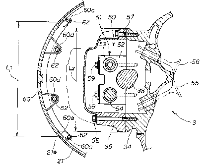
As shown in Fig. 3, the head cover 35 is mounted to a
top end of the cylinder head 34 such that it extends along
an axis of the camshaft 38. The head cover 35 has a large
depth and hence is relatively large in overall size.
Valve system chamber 50 is defined by the cylinder head
34 and head cover 35 and accommodates a valve system 51.
The valve system 51 comprises a camshaft holder 52 which,
jointly with the cylinder head 34, holds the camshaft 38.
The camshaft holder 52 also supports rocker shafts 53, 54.
Valves 55, 56 are driven by rocker arms not shown. Refer-
ence numerals 57, 58, 59, 59 designate bolts.
The bowl-shaped undercase 21 includes a wall portion 21'
(see Fig. 5) opposed to part of the head cover 35 extending
vertically (in the front-and-rear direction of the figure).
The wall portion 21' of the undercase 21 is provided with a
CA 02225007 1997-12-17
cutout 21a which corresponds in size to the head cover 35
and is opened in a front-and-rear direction. Stated other-
wise, the cutout 21a provided in the peripheral wall of the
undercase 21 opens in the direction of axes of the bolts 57,
58 which secure the head cover 35 to the cylinder head 34.
The cutout 21a is covered by a lid 60 which is releasably
secured thereto. The cutout 21a has a width L1 which is
larger than a width L2 of the head cover 35.
Lid 60 is constructed such that it can be fit into the
cutout 21a from inside the undercase 21, whereupon an exter-
nal surface of the lid 60 becomes flush with an external
surface of the peripheral wall of the undercase 21. In
other words, the lid 60 is held from inside against the
peripheral wall of the undercase 21 at an edge 60a thereof.
Referring now to Fig. 4, the cutout 21a is opened up-
wardly. An upper surface 60b of the lid 60 is flush with an
upper surface 21b of the peripheral wall of the undercase
21. The upper surfaces 60b, 21b are tightly joined with an
under surface 22b of the engine cover 22 via sealing packing
or seal 61 made of, for example, rubber.
Lid 60 is bolt fastened to the undercase 21. The lid 60
also includes a pair of upper brackets 60c, 60c provided at
an upper level on both sides thereof and a pair of lower
brackets 60d, 60d provided internally of the lid closely to
the center of the latter. The undercase 21 includes a pair
of upper supports or seats 21c, 21c and a pair of lower
supports or seats 21d, 21d, which are formed internally
_g_
CA 02225007 1997-12-17
thereof. The upper brackets 60c, 60c and lower brackets
60d, 60d are placed upon respective upper seats 21c, 21c and
lower seats 21d, 21d and fastened thereto by bolts 62.
The height of attachment of the lid 60 with respect to
the undercase 21 is determined by the height of the contact
surfaces between the upper seats 21c, 21c and upper brackets
60c, 60c. Thus, it becomes easy to place and keep upper
surfaces 60b, 21b of the lid 60 and undercase 21 flush with
each other. By virtue of the flush or linear packing sur-
face thus formed jointly by the upper surfaces 60b, 21b,
sufficient seal is achieved with respect to the engine cover
22. In other words, since the upper surfaces 60b, 21b do
not present any stepped or edged portions along the packing
surface, which may injure the seal 61, sufficient seal can
be established between the packing surface and the engine
cover 22.
After removal of the engine cover 22, the lid 60 can be
removed by simply untightening the bolts 62 within the
undercase 21 from above. The bolt fastened portions of the
undercase 21 and the lid 60 are invisible from outside and
hence are desirable from an aesthetic point of view.
Turning back to Fig. 2, mount level H2 of the bolts 57,
58 for mounting the head cover 35 falls within a range of
the cutout 21a of the undercase 21. More specifically, the
level of the upper surface 60b (Fig. 4) of the lid 60 is H1
while lower mount level of the bolts 57, 58 is H2. The
level H2 is positioned higher than the lower surface of the
_g_
CA 02225007 1997-12-17
cutout 21a of the undercase 21. A lower end of the cylinder
head 34 and a lower end of the head cover 35 are positioned
higher than the lower surface of the cutout 21a.
Referring to Fig. 5 in combination with Figs. 2 - 4,
discussion will be made next as to the manner for performing
maintenance and inspection operations on the engine 3 being
mounted to the engine body la.
As shown in Fig. 5, the engine cover 22 is first re-
moved. Then, the bolts 62 positioned internally of the
undercase 21 are removed from above, following which the lid
60 is removed by pulling it upwardly.
Thereafter, the bolts 57, 58 as shown in Fig. 3 are
removed so that the head cover 35 can be removed from the
cylinder head 34. The head cover 35 is mounted to the
cylinder head 34 to lie along the axis of the camshaft 38
and hence has a large depth dimension and is large in over-
all size. However, since the width L1 of the cutout 21a is
larger than the width L2 of the head cover 35, the head
cover 35 can be removed easily by first pulling it toward
the cutout 21a and then lifting it up. The same applies to
mounting the head cover.
Lastly, the cylinder head 34 is removed from the cylin-
der block 33, whereby maintenance and inspection operations
can be made on the engine 3 which remains mounted to the
engine body la.
Engine 3 can be assembled again by following the above-
described disassembling steps backwardly.
-10-
CA 02225007 1997-12-17
As can be appreciated from Fig. 2, with the engine 3
mounted to the engine body la, it is not possible to remove
the undercase 21 from other cases (such as the mount case
2). However, the lower ends of the cylinder head 34 and
head cover 35 are positioned higher than the lower end of
the cutout 21a. As a result, after removal of the lid 60,
the cylinder head 34 and head cover 35 can be removed
through the cutout 21a, thereby allowing access to the
inside of the engine 3 for maintenance and inspection opera-
dons on the latter, with the engine 3 and undercase 21
mounted to the engine body la.
In the above-described preferred embodiment of the
invention, any number of the bolts 62 may be used for fas-
tening the lid 60 to the undercase 21.
Obviously, various minor changes and modifications of
the present invention are possible in the light of the above
teaching. It is therefore to be understood that within the
scope of the appended claims, the present invention may be
practiced otherwise than as specifically described.
-11-