Note: Descriptions are shown in the official language in which they were submitted.
CA 02225472 2002-O1-21
(a) TITLE OF THE INVENTION
APPARATUS FOR PACKING CONNECTOR PLATES
(b) TECHNICAL FIELD TO WHICH THE INVENTION RELATES
The present invention relates to an apparatus for packing connector plates or
the like.
(c) BACKGROUND OF THE INVENTION
The connector plates are manufactured, for example, so that rectangular-shaped
plates
are separated from a metal blank, in which teeth are formed by stamping acute-
pointed
triangular parts to be bent to a substantially-perpendicular position with
respect to the
plates. The finished connector plates comprise several parallel rows of teeth.
The teeth can
also be formed in a continuous band-like metal blank. The individual plates
are separated
therefrom by cutting. Connector plates and manufacturing methods thereof are
shown, for
example, in U.S. Patents Nos. 4,527,933, issued July 9, 1985, to Karhumaki, et
al. and
3,479,919, issued Nov. 25, 1969 to J. Lidsky.
After the manufacturing method, the connector plates travel to a station where
the
plates are stacked in a uniform orientation, e.g., so that the teeth point
upwardly. The
finished connector plates are packed, depending on the manner they are finally
used, as a
stack either so that the teeth in the package extend in the same direction, or
most preferably
so that the connector plates are formed into nested pairs, where the teeth of
the connector
plates lie opposite to each other and the teeth of one plate are intermeshed
with those of
another plate. In the latter case, it is necessary, preferably, to turn every
other connector
plate upside down, i.e., so that the teeth project downwardly, before the
packing step to
form the above-mentioned pairs of connector plates. The turning can be
performed either
manually or in an automated manner, depending on the size, manufacturing speed
or
amount of the connector plates.
In known automatic solutions for turning the connector plates to form the
pairs, belt
conveyors or the like are usually used between the manufacturing step and
packing step. In
a known technical solution, the conveyors, which usually are two or more in
number, but
always an even number, lie in parallel. The connector plates are introduced
onto one of the
conveyors of a pair, for conveying them unturned to the stacking station which
is located
1
CA 02225472 2002-O1-21
before the packing step. The connector plates which are to be turned are
introduced on the
other one of the conveyors for conveying them to a location where they are
turned over.
More specifically, the latter of the conveyors conveys the connector plates to
the end,
where a swinging arm, which is pivotable in a plane which is perpendicular to
the transfer
direction of the conveyors, turns the connector plate along a semi-circular
path
downwardly on top of a connector plate that has entered the stacking station
through the
end of the first conveyor. The turned and unturned connector plates are
arranged to enter
the stacking station alternately, whereby they are automatically formed into
above-described nested pairs of connector plates.
Manual turning and stacking of connector plates is slow and increases the
production
costs of connector plates and is not therefore suitable for a manufacturing
method of large
capacity. Known automated solutions require considerable floor area both
longitudinally
and laterally because of parallel conveyors. The use of additional devices
and/or manual
operation further away from the conveyors is required. The swinging arm of a
known
apparatus for turning the connector plates requires a long path of movement
and return
movement, which decreases the handling capacity. A similar approach is
represented by
German Patent No. 32-37-255 showing an apparatus for stacking grid plates
coming along
two parallel lines.
(d) DESCRIPTION OF THE INVENTION
It is an object of one aspect of the present invention to provide an apparatus
for
packing connector plates which helps greatly to eliminate the above described
drawbacks
which are associated with known solutions and thus to improve the current
state of the art.
A first broad aspect of this invention provides an apparatus for stacking
generally
thin pieces at a stacking station, the pieces having projections extending
from a side of each
piece. The apparatus includes a first conveyor for conveying pieces along a
first path
toward the stacking station with the projections of the pieces extending
generally upwardly.
The apparatus further includes a second conveyor for conveying pieces along a
second path
to the stacking station. The second conveyor inverts the pieces before the
pieces reach the
stacking station so that the projections of the pieces extend downwardly in
the stacking
station and intermesh with the projections of the pieces which have already
been conveyed
2
CA 02225472 2002-O1-21
to the stacking station by the first conveyor. The first and second paths are
non-coincident.
The second conveyor is arranged with respect to the first conveyor so that
pieces on the
second conveyor, which are moving along the second path, move downwardly into
the
stacking station, while the pieces on the first conveyor, which are moving
along the first
path, enter the stacking station from one side of the stacking station.
By a first variant of this first broad aspect of this invention, the first and
second paths
are co-planar. By a first variation thereof, the second path is generally semi-
circular.
By a second variant of this first broad aspect of this invention, and/or the
above first
variant thereof, the second conveyor is positioned for capturing pieces from
the first
conveyor to move along the second path.
By a first variation thereof, the second conveyor comprises means for
supporting a
captured piece. By a second variation thereof, the support means comprises
resilient
members which are disposed for entraining pieces on the first conveyor,
thereby to capture
the pieces for movement on the second conveyor. By a third variation thereof,
the resilient
members each comprise flexible bristles. By a fourth variation thereof, the
second
conveyor comprises a pair of opposed discs which are mounted for rotation
about a
generally-horizontal axis, the discs being located on opposite sides of the
first conveyor,
and each disc having the support means thereon, the support means on each disc
cooperating to lift pieces off of the first conveyor one at a time and one
after another and to
move the pieces by rotation along the second path to the stacking station. By
a fifth
variation thereof, the second conveyor further comprises a slide barrier which
is
engageable by the pieces being moved along the second path for maintaining the
pieces at a
selected radial position relative on the discs.
By a third variant of this first broad aspect of this invention, and/or the
above
variants thereof, the apparatus further includes a distributor which is
disposed at an
intersection of the first and second conveyors, the distributor being
selectively movable
between a stopping position, in which the distributor stops a piece which is
moving with
the first conveyor to permit the second conveyor to capture the piece, and a
retracted
position, in which the distributor is out of the path of pieces which are on
the first
conveyor, thereby permitting the pieces to travel downstream of the
distributor on the first
conveyor to the stacking station.
CA 02225472 2002-O1-21
By a first variation thereof, the apparatus further includes a guide for
inhibiting
engagement of the support means of the second conveyor with the pieces on the
first
conveyor for preventing the support means from capturing pieces on the
conveyor when the
first distributor is in the retracted position. By a second variation thereof,
the guide is
movable between a first position, in which it inhibits engagement of the
support means
with the pieces which are on the first conveyor, and a second position in
which it permits
engagement of the support means with the pieces on the first conveyor.
By a fourth variant of this first broad aspect of this invention, and/or the
above
variants thereof, the apparatus further includes in combination with the
stacking station,
and the stacking station comprises a generally-vertically-extending shaft for
receiving a
stack of the pieces which are arranged in nested pairs.
A second broad aspect of this invention provides an apparatus for stacking
generally-
thin pieces at a stacking station, the pieces having projections extending
from a side of each
piece. The apparatus includes a first conveyor for conveying the pieces along
a first path
toward the stacking station with the projections of the pieces extending
generally-upwardly.
The apparatus further includes a second conveyor for conveying the pieces
along a second
path to the stacking station. The second conveyor inverts the pieces before
the pieces reach
the stacking station so that the projections of the pieces extend downwardly
in the stacking
station and intermesh with the projections of the pieces which have already
been conveyed
to the stacking station by the first conveyor. The second conveyor is
positioned for
capturing pieces from the first conveyor to move along the second path. The
second
conveyor comprises resilient members for supporting a captured piece, the
resilient
members being disposed for entraining pieces on the first conveyor, thereby to
capture
those pieces for movement on the second conveyor.
By a first variant of this second broad aspect of this invention, the
resilient members
each comprise flexible bristles.
By a second variant of this second broad aspect of this invention, and/or the
above
first variant thereof, the second conveyor comprises a pair of opposed discs
which are
mounted for rotation about a generally-horizontal axis, the discs being
located on opposite
sides of the first conveyor, and each disc has the support means thereon, the
support means
on each disc cooperating to lift pieces off of the first conveyor one at a
time and one after
4
CA 02225472 2002-O1-21
another, and to move those pieces by rotation along the second path to the
stacking station.
By a first variation thereof, the second conveyor further comprises a slide
barrier which is
engageable by the pieces which are being moved along the second path for
maintaining the
pieces at a selected radial position relative on the discs.
A third broad aspect of this invention provides apparatus for stacking
generally-thin
pieces at a stacking station, the pieces having projections extending from a
side of each
piece. The apparatus includes a first conveyor for conveying the pieces along
a first path
toward the stacking station with the projections of the pieces extending
generally-upwardly.
The apparatus further includes a second conveyor for conveying the pieces
along a second
path to the stacking station. The second conveyor inverts the pieces before
the pieces reach
the stacking station so that the projections of the pieces extend downwardly
in the stacking
station and intermesh with the projections of the pieces which have already
been conveyed
to the stacking station by the first conveyor. The second conveyor is
positioned for
capturing the pieces from the first conveyor to move them along the second
path. The
second conveyor comprises means for supporting a captured piece. The apparatus
further
includes a distributor which is disposed at an intersection of the first and
second conveyors.
The distributor is selectively movable between a stopping position, in which
the distributor
stops a piece which is moving with the first conveyor to permit the second
conveyor to
capture the piece, and a retracted position, in which the distributor is out
of the path of
pieces which are on the first conveyor, thereby permitting the pieces to
travel downstream
of the distributor on the first conveyor to the stacking station.
By a first variant of this third broad aspect of this invention, the apparatus
further
includes a guide for inhibiting engagement of the support means of the second
conveyor
with the pieces on the first conveyor for preventing the support means from
capturing
pieces on the first conveyor when the distributor is in the retracted
position. By a first
variation thereof, the guide is movable between a first position, in which it
inhibits
engagement of the support means with the pieces on the first conveyor, and a
second
position in which it permits engagement of the support means with the pieces
on the first
conveyor.
As specified above, in the apparatus according to an embodiment of an aspect
of the
invention, the transfer of the connector plates to the stacking station
without turning takes
' ' CA 02225472 2002-O1-21
place along a line which is parallel to the line of travel or "transfer path"
of the connector
plates which are to be turned. The turning of the connector plates is
performed gradually
along the transfer path which is parallel to the transfer path of the
connector plates left
unturned, and preferably which is disposed above the transfer path of the
unturned plates.
The apparatus does not require separate devices or manual work for separating
the
connector plates in the lateral direction into those which will be turned and
those which
will not be turned while they are being transferred from the manufacturing
method.
Moreover, the stacking of the connector plates in the end of the transfer
paths takes place
automatically. One important advantage of the apparatus according to an aspect
of this
invention is that the floor area required by it is considerably smaller, both
in the lateral and
longitudinal directions, compared with known solutions. An advantage also
resides in the
fact that the apparatus can be adjusted with small modifications and without
any accessory
devices to accommodate connector plates of different length, width or other
dimensions.
Several of the apparatus can be used together in association with a single
connector plate
manufacturing process.
(e) DESCRIPTION OF THE FIGURES
In the accompanying drawings,
FIG. 1 is a side view of the apparatus of an embodiment of an aspect of this
invention;
FIG. 2 is a top view of the apparatus of an embodiment of an aspect of this
invention;
FIG. 3 is a representation of section A-A of FIG. 1; and
FIG. 4 is a representation of section B-B of FIG. 1.
(fj AT LEAST ONE MODE FOR CARRYING OUT THE INVENTION
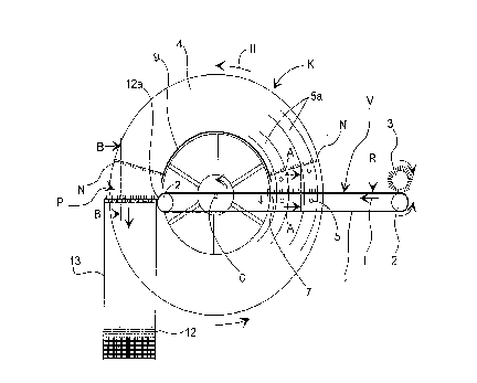
As shown in FIGS. 1 and 2, the apparatus according to one embodiment of an
aspect
of this invention comprises a horizontal conveyor V, which is preferably a
belt conveyor
comprising a conveyor belt 1 extending around at least two rolls 2. Connector
plates N are
fed to the horizontal conveyor V by a feed roll 3 or the like while the
conveyor belt 1
moves in direction I. The horizontal conveyor V is placed to form a direct
extension of the
manufacturing line of the connector plates. The connector plates N are fed in
a position
6
__
CA 02225472 2002-O1-21
where their teeth are pointing upwardly from the connector plate. The
horizontal conveyor
V transfers the connector plates N to a stacking station P which is situated
at the other end
of the horizontal conveyor V as an extension thereof. From this point, the
connector plates
N are further transferred in a stack to be packed into boxes, onto pallets or
the like.
The apparatus according to one embodiment of an aspect of this invention, also
a
turning conveyor K for conveying the connector plates N to the stacking
station P in a
position where they are turned upside down for the purpose of achieving a
stack of
connector plates together with the horizontal conveyor V . In the stack, the
connector plates
N are arranged in nested pairs such that the teeth in each pair of connector
plates are in an
intersticed relationship. The turning conveyor K includes two parallel,
vertical, disk-shaped
support walls 4, which are connected to a common horizontal axle 6 which is
provided for
rotation thereabout in the direction of arrow II. As is apparent from FIGS. 1
and 2, the
horizontal conveyor V lies partly between the support walls 4, and it is
further positioned
so that the upper section of the conveyor belt 1 preferably travels as close
to the centre of
the turning conveyor and to the axle 6 as possible, but slightly above it. In
accordance with
FIGS. 1 and 2, in the space between the support walls 4, an annular plate
housing 10 is
defined by the outermost portions 4a of the support walls 4 and by slide
barriers 9, which
prevent the connector plates N from sliding radially from the plate housing 10
towards the
centre of the turning conveyor K. The slide barrier 9 forms an abutment for
the end of a
connector plate N nearest the axle 6. The slide barrier 9 can be attached in a
fixed position
on the frame of the apparatus so that it extends above the horizontal conveyor
V .
As seen in FIGS. 1, 3 and 4, substantially-horizontal support means 5 are
placed on
the support walls 4 within the area of the portions 4a. On each support wall
4, two support
means 5 are disposed at spaced positions on a radial line extending from the
centre of the
support wall. Multiple, radially-aligned pairs of support means 5 are located
at angularly-
spaced positions around each support wall 4. Preferably, each pair of support
means 5 is
co-planar with a pair of support means 5 on the opposite support wall 4, and
each support
means 5 in the pair is in opposed relation with a corresponding support means
5 on the
other support wall 4. The support means 5 may be pivotable pins, shelves or
the like,
relatively short in construction, which are connected to the support walls 4
through hinges
or through an equivalent method. According to an advantageous solution shown
in FIG. 3,
7
CA 02225472 2002-O1-21
the support means may be by means consisting of flexible bristles. The purpose
of the
support means 5 is to receive a connector plate N from the conveyor belt 1 of
the
horizontal conveyor V to carry it while the turning conveyor K is rotating in
direction II,
so that the connector plate N will be transferred during the rotation movement
to the
stacking station P while being turned upside down. As shown in FIG. 1, support
strips Sa
having pre-assembled support means 5 at regular intervals thereon, can be
mounted on the
support walls 4. For assembling the support strips in the support walls 4, the
support walls
can be further provided with assembly grooves or the like, in which the
support strips can
be placed. The assembly grooves are not shown in the accompanying figures.
Hence, the turning conveyor K will gradually turn the connector plates N over
while
the connecting plates N are travelling along a transfer path which is parallel
to the transfer
path of the horizontal conveyor V. The turning conveyor K can hold several
plates N at
angularly spaced locations. Only a short rotary movement of the turning
conveyor K is
needed for stacking.
A distributor 7 is provided for separating the connector plates N to be turned
by the
turning conveyor K from those to be guided to the plate housing 10 by the
horizontal
conveyor V . The distributor 7 is disposed in the path of travel of the
connector plates N
advancing on the horizontal conveyor V to stop a connector plate N to be
separated.
According to an advantageous embodiment shown in FIGS. 2-4, the conveyor belt
1
consists of three separate parallel belts la or the like, and the distributor
7 is adapted
alternately to rise from gaps between the belts in front of a connector plate
N to be
separated to stop it, and to be lowered to allow a connector plate N to
continue its travel on
the conveyor belt 1 towards the stacking station P. In order that the
connector plate N to be
turned reaches the stacking station P at the proper time, the connection plate
N must be
immediately picked up by the support means 5 passing the conveyor belt 1. In
order to
carry out this function, the location at which connector plates N to be turned
over are
separated from the horizontal conveyor V is provided with a rising and falling
support
guide 8 having a raised position and a lowered position. Lateral edges of the
support guide
8 are adjacent respective support walls 4. In the raised position, the support
guide 8
prevents the support means 5 from entraining the connector plate located at
the support
guide by deflecting the support means 5 downwardly. The support guide 8 is so
situated in
CA 02225472 2002-O1-21
the raised position that it does not prevent , i.e., it permits, the travel of
the connector
plate N on the horizontal conveyor V. As the distributor 7 rises to stop the
connector plate
N to be turned over in the plate housing 10, the support guide 8 is lowered
down, so that
the connector plate N will be lifted on the support means 5 upwardly from the
horizontal
conveyor V . Thereafter, the distributor 7 and the support guide 8 are
returned to their
previous positions and the next connector plate will have a clear passage on
the horizontal
conveyor V to the stacking station P.
Another possibility for entraining a connector plate N on the support means 5
is to
position a lifting means (not shown) below the horizontal conveyor V at the
stop point of
the connector plate N. The lifting means rises from between the belts la and
lifts the
connector plate N from the horizontal conveyor in the direction of the
movement of the
turning conveyor K. If there is a risk that the densely-spaced support means 5
will come to
lie directly in the way of the conveyed connector plates, barriers (not shown)
can be
arranged on the level of the edges of the connector plate N for bending any
flexible support
means 5 lying on the same level with the conveyor K away from an obstructing
position.
After the connector plate N has passed its uppermost position during the
rotational
movement of the turning conveyor K, it will fall to the support of the support
means 5
travelling ahead while being lowered toward the stacking station P, where it
is laid on top
of a connector plate N that is in uppermost position in the stack of connector
plates and has
entered from the horizontal conveyor V . At this moment, the teeth of these
connector
plates will be nested between each other.
In order to release the connector plate N from the support means 5, the
stacking
station P is provided on both sides of the stack of connector plates N, with
releasers 11.
The releasers 11 turn the support means 5 contacting them away to lie parallel
with the
support walls 4, the connector plate N being thus allowed to fall freely on
top of the stack
of connector plates N. The releasers 11 can be plate-like pieces in accordance
with the
advantageous embodiment of FIG. 4, being arranged stationary at the plate
housing 10, or
to move back and forth in a substantially-horizontal direction into the plate
housing 10 and
away therefrom. The latter arrangement causes only the support means 5
supporting the
connector plate N to be in contact with the releasers 11. Such arrangement is
able to
decrease the wear of the support means and releasers.
9
CA 02225472 2002-O1-21
According to the advantageous embodiment of FIG. 1, the stacking station P is
provided with a substantially-vertical stacking shaft U, where the connector
plates N
coming from the turning conveyor K and horizontal conveyor V are gathered for
further
handling, e.g., for packing. The stacking shaft U preferably comprises at
least a front wall
12 and a back wall 13 as well as, if needed, also side walls (not shown in the
figures),
which can be partially defined by the support walls 4. At the upper end of the
front wall 12
there is a guide extension 12a which is arched toward the horizontal conveyor
V . The
purpose of the guide extension 12a is to guide a connector plate N coming from
the
horizontal conveyor V into the stacking shaft U. The downward adjustment of
the upper
surface of the stack of connecter plates N can be accomplished with spring
arrangements,
hydraulically or in some other suitable known manner required for further
handling of the
connector plates N after they are stacked. The connector plates N can travel
down in the
stacking shaft U as a continuous stack and be subjected to a packing operation
in the
terminal end of the stacking shaft U. The stacking shaft U can continue
straight down or be
curved following a radius of suitable length. The end of the stacking shaft U
can have a
pusher (not shown) which pushes part of the stack emerging from the stacking
shaft U in
the direction of the planes of the connector plates N toward the location
where packing of
the connector plates N takes place.
The movements of the horizontal conveyor V, the turning conveyor K, the feed
roll
3, the distributor 7 and the support guide 8 are accomplished by actuators,
e.g., by electric
motors and/or pneumatic actuators. Known control automation techniques can be
used in
the control of movements. It will be understood that depending upon the range
of
movements of the distributor 7 and the support guide 8, the conveyor belt of
the horizontal
conveyor V can be adapted to travel, for example, downwardly over a third roll
(not
shown) or the like which is disposed below the horizontal level of the
remainder of the
horizontal conveyor V .
The horizontal conveyor V is most preferably adapted to convey connector
plates N
while the conveyor belt 1 is operating continuously. Alternatively to the
continuous
movement, wherein the speeds of the horizontal conveyor V and turning conveyor
K are
coordinated to transfer the connector plates N in a synchronous manner to the
stacking
station P, the turning conveyor K can be adapted for indexed rotation at
predetermined
CA 02225472 2002-O1-21
intervals and for predetermined periods. The support means 5 captures one
connector plate
N during one period of rotation and, for example, during the same period or
rotation, a
connector plate N is released from the support means at the stacking station
P. The support
means 5 can also be positioned on the support wall 4 according to the movement
lengths so
that a connector plate N to be fed to the turning conveyor K will always be
received on
some support means during each movement period of the turning conveyor K, in
which
case the guide support 8 is unnecessary
Any desired modification of the apparatus and in particular the plate housing
10 to
comply with different sizes of connector plates N sizes can be accomplished in
several
ways. It is, for example, possible to use outermost portions 4a of the support
wall 4 having
different sizes or shapes to adjust the distance between the support walls 4
on the axle 6
and further to use each time a correspondingly sized support guide.
Further, before the turning conveyor K there can be a discharge device which
is
associated with the horizontal conveyor V. The purpose of this discharge
device is to
remove from the conveyor V samples or pieces containing a weld connection
between
successive blank bands from which the connector plates N are formed. The
discharge
device, whose possible location is designated by arrow R in FIG. 1, can, for
example, rise
from beneath the conveyor V and remove the connector plate N from the conveyor
V.
The construction of the apparatus is not restricted only to the solutions
shown in
FIGS. 1-4. The function of the turning conveyor K, which gradually turns the
connector
plates N over, can be accomplished by different mechanisms. It is essential
that the transfer
part of the turning conveyor hold the connector plates N at several
intermediate positions
before depositing the connector plates N turned over in a stack at the
stacking station. A
connector plate N is deposited in the stack at the stacking station P by a
short rotary
transfer movement of the turning conveyor K.
Finally, although the apparatus is especially well suited for handling
connector plates
N, it can be used to handle all plate-like pieces. Generally, the apparatus
will handle such
pieces which are asymmetrical about a plane which can be stacked so that the
structure
producing the asymmetry nests with the corresponding structure on another
identical piece
to reduce the height of a stack of pieces. Equivalent such pieces where one of
the flat sides
11
CA 02225472 2002-O1-21
has protrusions or projections (e.g., the teeth of a connector plate N) and
the other one is
devoid of such protrusions or projections are typical examples.
A turning conveyor disc with an outer diameter under one metre is sufficient
for
stacking normal-sized connector plates, which are used, e.g., in roof trusses,
resulting in
minimal space requirement both in horizontal and vertical direction. However,
the
apparatus can be dimensioned to comply with various sizes and types of pieces
to be
stacked.
12