Note: Descriptions are shown in the official language in which they were submitted.
, CA 0222~474 1997-12-22
Folding container for transporting objects
This invention relates to plastic folding containers for transporting objects
such as fruit and vegetables that has inward folding side walls so that the con-tainer can be converted from a receiving position, in which the side walls are
perpendicular to the bottom, to a folded position in which the container can be
stowed without requiring much space.
Such folding containers are known in various designs. The joints used are
mainly joint hinges, although they constitute the weak point of such a folding
container because they can be d~maged under load and with frequent use. Such
containers, which are mass-produced goods, are not treated carefully during use;they are mostly unfolded very quickly and with force, which can soon lead to
damage unless the joint hinges are of el~Llehlely robust combustion. HoweYer, ifthe joint hinges are of robust combustion they take up a lot of superfluous space
and furthermore increase the total weight of the folding container, which is in
turn disadvantageous for han-1ling.
The problem of the invention is to provide a folding container which can
be easily mounted and dismounted, is of extremely stable and robust construc-
tion, and whose joint hinges are no longer the weak point of the folding con-
tainer. Furthermore the container should be easy to handle.
This problem is solved according to the invention by the features con-
tained in the characterizing part of claim 1, expedient developments of the in-
vention being characterized by the features contained in the subcl~ims.
According to the invention, the joint hinges are formed as an eye and pin
integrally with parts of the container and each hinge has at least one joint pinand at least one joint eye, the joint eye being divided into two parts or two halves
one of which forms a fLxed hinge part and the other of which is adapted to be
folded onto the fixed hinge part and firmly locked therewith. The two-part divi-sion of the joint eye permits the container bottom to be formed integrally with
the hinge mer.h~ni.qm for example. In the injection molding position the fi2ced
hinge part and mounting hinge part lie unfolded side by side and are connected
via a filmlike joint. After being lifted out of the injection mold, the mounting
CA 0222~474 1997-12-22
hinge part can be folded via the film hinge onto the fixed hinge part and lockedtherewith, whereby the joint pin, which is preferably formed integrally on a
folding side wall part, is enclosed between the two halves of the hinge. The f~ed
hinge part is formed in a skirt profile of the bottom whereas the mounting hingepart is integrated into a profile strip to be folded onto said skirt profile, or vice
versa. In the folded-together position of the profile strip on the skirt profile, the
profile strip is supported on the skirt profile via contact surfaces, the load
transmission from the side walls being effected via these contact surfaces. Be-
cause of these contact surfaces the joint hinge mech~ni~m is essentially unin-
volved in the load transmission, so that the profile strip forms separate segments
for load tr~n.qmi~ion and for swivel motion. This considerably relieves the joint
hinges. A further advantage of the invention is that when the side walls are
pressed outward a bracing occurs via the contact surfaces and the outward mo-
tion of the side walls is blocked. Even in this case there is no load on the joint
hinges and the container has a stable unfolded position. One expediently uses a
multiplicity of closely spaced joint hinges in a row on each side wall so that the
joint hinges are disposed in the manner of a ring binder. If one joint hinge fails
due to breakage or other damage, its function is performed by the other joint
hinges.
In another embodiment of the invention, the side walls are locked to-
gether by snap-in mechanisms, the lock being effected by snap-in noses disposed
on the lateral edges of two opposite side walls. In the locked position, the noses
engage behind corl e~onding detent hooks in the diagonally adjacent side walls.
When one wants to convert the folding container from its erect position to the
folded position, one must merely compress the V- or U-shaped noses so that they
can be guided past the detent hooks and the side wall thereby folded inward. If
there is pressure on a side wall in the unfolded position, however, there is no
unintentional folding inward of the side wall in question since the V- or U-
shaped noses cause a mutual bracing of the unfolded side walls which prevents
the side walls from folding up.
In the following some preferred examples of the invention will be de-
scribed with reference to the drawings, in which:
CA 0222~474 1997-12-22
Fig. 1 shows a side view of the narrow side of a folding container from the
outside,
Fig. 2 shows a view of the long outer side of the folding container,
Fig. 3 shows a view analogous to Fig. 1 but in section on the left half,
Fig. 4 shows a view analogous to Fig. 2 but in section on the left half,
Fig. 5 shows a view of the folded-up container, the left half being again
shown in cross section,
Fig. 6 shows a sectional view through a container half with inward folded
side walls,
Fig. 7 shows a sectional view comparable to Fig. 6 with the mounting
hinge folded on,
Fig. 8 shows a sectional view analogous to Fig. 6 with various positional
views of the folding hinge part,
Fig. 9 shows a sectional view analogous to Fig. 7 with various positional
views of the folding hinge part,
Fig. 10 shows a sectional view analogous to Fig. 6 in the locked position of
the folding hinge part,
Fig. 11 shows a sectional view analogous to Fig. 7 of the folding hinge part
in the locked position,
Fig. 12 shows a view corresponding to Fig. 11 in an enlarged view with a
longitudinal section through a joint hinge,
Fig. 13 shows a sectional view comparable to Fig. 12 with a folded-upward
side wall,
Fig. 14 shows a sectional view with inward folded side walls,
Fig. 15 shows a sectional view corresponding to Fig. 14, the section being
shifted,
Fig. 16 shows two folded-up containers in the stacked position,
Fig. 17 shows partial section C of Fig. 3 to illustrate the side wall locking;
and
Fig. 18 shows sectional view D of Fig. 3 to illustrate the locking of both
side walls.
CA 0222~474 1997-12-22
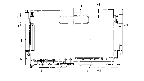
The folding container shown in Figs. 1 to 4 in an outside view and partly
in a sectional view is produced integrally and includes bottom 1 with a rectangu-
lar or square plan view and four side walls, namely two opposite narrow side
walls 2 and two opposite long side walls 3 on which handling openings formed by
recesses 4 are present. All four side walls 2, 3 can be folded inward, namely along
joint hinges 5 to be described more closely below. The folded-up position of thefour side walls can be seen in Fig. 5.
As indicated best by Figs. 1, 3 and 4, elevated skirts 6, 7 are molded on
bottom 1, having the side walls hinged thereto at 8. These elevated skirts are
coordinated in their height so as to permit the corresponding side wall hinged
thereto to be folded over another side wall of the container. For example skirt 6
according to Fig. 4, i.e. the skirt associated with long side wall 3, is formed
higher than skirt 7 located on the narrow side so that narrow side wall 2 is first
folded inward onto bottom 1, with reference to Fig. 4, and then higher hinged
long side wall 3 is folded over side wall 2 already folded. This also results quite
clearly from Fig. 5, where long side walls 3 are folded over narrow side walls 2already folded inward before. This is obtained by the different height of the skirt
in accordance with the particular folded positions.
The formation of joint hinges 5 is explained best with reference to Figs. 6
to 12. Fig. 12 shows that at the lower edge of the side walls, for example narrow
side wall 2 here, several hinge bolts 8 are disposed at regular intervals over the
length of the lower edge of side wall 2, that is, molded onto side wall 2. However,
on account of the sectional view in Fig. 12 one can only see in detail one of hinge
bolts 8, which is molded on side wall 2 via two flanges 9.
As indicated best by Fig. 12 top left, each hinge bolt 8 is received in joint
eye 10 embracing hinge bolt 8. Joint eye 10 is divided in two, the plane of divi-
sion being marked as 11. If hinge bolt 8 is completely encompassed by eye 10 in
the sectional view of Fig. 12 top left, this is only due to the course of the cutting
plane. One can see quite clearly from Figs. 4 and 14 for example that hinge bolt 8
is fully received in a circular recess of joint eye 10 so that a perfect position and
thus joint function is obtained.
CA 0222~474 1997-12-22
Figs. 6 and 7 show the folding container as it is taken out of the injection
mold, Fig. 6 being a section that shows snap-in mechanism 12 and Fig. 7 a sec-
tion that shows joint eye 10. Specif~lcally, profile strip 13 is hinged via thin film-
like connecting part 14 to skirt 6, which is formed here as a downwardly open
profile and designated a skirt profile in the following, whereby mounting hinge
part 10b of joint eye 10 and also the part of snap-in me-h~ni~m 11 are formed inprofile strip 13. To form the joint, profile strip 13 is merely folded about flexible
connecting part 14 onto skirt profile 6, as indicated by Figs. 8 and 9, so that de-
tent hook 12 snaps in behind snap-in nose 15 formed in skirt profile 6. Similarly,
mounting hinge part 10b passes onto the complementary half of the eye formed
in skirt profile 6, so that the eye formation in profile strip 13 and fixed hinge
part 10a in skirt profile 6 complement each other to form joint eye 10.
Plane of division 11 of bipartite eye 10 is shown again in Fig. 9. Figs. 10
and 11 show the functional position where the catch or catches engage behind
detent hook 15 and the two eye formations 10a, 10b complement each other to
form joint eye 10. Figs. 10, 11 and 12 indicate quite clearly that in the functional
position of the joint hinge, where profile strip 13 is folded onto skirt profile 6, the
two eye formations 10a, 10b mate with their surface on plane of division 11, i.e.
according to Fig. 7 for the entire contact surface marked as 16 to the left and
right of eye formation 10b including protruding leg 17 of profile strip 13, result-
ing according to Fig. 12 in a very good contact surface over the width of skirt
profile 6, namely along plane of division 11. If one presses long side wall 3 out-
ward about hinge bolt 8 counterclockwise according to Fig. 12, lower side wall
surface 18 will press on profile strip 13 so that the latter is braced against skirt
profile 6. The joint hinge is not loaded thereby. Because of m~ting contact sur-faces 16 on plane of division 11 a bracing occurs and thus an intensification ofthe joint hinge engagement, whereby in particular legs 17 of profile strip 13 and
skirt profile 6 press on each other, so that outward swiveling of side walls 2, 3 is
effectively blocked by the formation of skirt profile 6 and profile strip 13. That is,
the folding container is protected very effectively against side walls 2, 3 swinging
outward in the folded-upward position of the side walls, so that a very stable un-
folded position of the side walls is obtained. That is, profile strip 13 in snap-in
CA 0222~474 1997-12-22
engagement with skirt profile 6 forms a folding stop for unfolded side walls 2, 3
that prevents them from swinging further out of the upright position. In this
position, very good load removal in the stack is also possible, in such a way that
the hinge mechanism is largely relieved. The hinge mechanism is accordingly
spared. This formation ensures a division into components for load tr~n.qmi~ion
and for swivel motion, so that both the eyes and the hinge bolts are largely re-lieved and are used only for swivel motion. As indicated in particular by Figs. 3
and 13, a multiplicity of spaced hinges OEe provided on each side wall, resulting
in a ring binder-like hinge formation. This has the advantage that if one hinge
formation or hinge bolt breaks, the hinge function can be performed by the otherhinges. The hinge formations as described here are obviously only intended by
way of example, so that one can also use longer hinge bolts that span or reach
through several joint eyes. Hinge bolts or pins 8 can also have a cross section
different from the circular cross section shown, for example a triangular cross
section, which is advantageous in terms of production engineering. It is expedi-ent if the hinge bolts are connected at both ends to the side walls via flanges 9,
since this is of advantage for the stability of the hinge bolts.
Fig. 16 finally shows the stacking of folded-up containers, whereby foot
formations 19 on bottom 1 ensure a lateral stack engagement with lower edges
18 of the side walls, thereby obt~ining a certain fixation of the stacked, folded-up
folding containers.
Figs. 17 and 18 show the locking of unfolded side walls 2, 3, whereby V- or
U-shaped snap-in noses 19 are provided here for example on side wall 2 on the
left and right, i.e. in the area of side walls 3, for grasping behind corresponding
detent hooks 20 on side walls 3. If one wants to fold side wall 2 inward onto the
bottom one need merely compress the two noses 19 manually so that front por-
tion 21 of noses 19 gets past detent hook 20 and wall 2 can be folded inward. Onthe other hand, automatic blocking is effected via the snap-in mechanism when
wall 2 is inadvertently pressed inward for ex~mple, since noses 19 are then
braced before detent hook 20. This also ensures a stable unfolded position of the
container. The folding process, i.e. the folding in of the side walls, presupposes
that suitable pressure is exerted manually on noses 19 by compression of noses
CA 02225474 1997-12-22
19. Only then can the noses be guided inward past detent hooks 20. Uninten-
tional collapse of the side walls of the container is thus excluded. Pressing on the
side walls would instead only cause an obstruction of the walls via noses 19.