Note: Descriptions are shown in the official language in which they were submitted.
CA 02225767 1997-12-23
96-1-341 -1- PATENT APPLICATION
THEFT-RESISTANT ASSEI~LY FOR
E'LUORESCENT I~AI4pS
FIELD OF T8$ INVENTION
This invention relates to apparatus for deterring
theft of fluorescent light bulbs, and is directed more
particularly to an assembly for deterring theft of
screw base compact fluorescent light bulbs from lamps
in which the fluorescent bulbs are mounted in sockets
for conventional incandescent light bulbs.
BAC1C~3ROUND OF T88 INVENTION
The advantages of fluorescent bulbs over
incandescent bulbs of equivalent light intensity are
well known. Though initially more expensive, the
additional cost is more than offset by reduced energy
consumption and extended operating life.
.. CA 02225767 1997-12-23
96-1-341 -2- PATENT APPLICATION
To benefit from the advantages of fluorescent
lighting, adapters have been developed which
facilitate replacing conventional incandescent light
bulbs with compact U-shaped fluorescent bulbs.
Adapters typically include a starter circuit and
ballast transformer. The U-shaped bulb that is used
with the adapter usually includes, at a base portion
thereof, a pair of terminal pins that plug into
matching receptacles on the adapter to connect the
fluorescent bulb to the ballast transformer and
starter circuit. The adapter is threaded so that it
readily can be installed in a conventional
incandescent light socket, common in table lamps and
floor lamps.
It is known to provide interlocking means in
adapters for securing the U-tube in the adapter, for
preventing easy removal of the U-tube from the
adapter. Such means are shown and described in U.S.
Patent No. 4,637,671, issued January 20, 1989, to
George E. Johnson, et al; and U.S. Patent No.
CA 02225767 1997-12-23
96-1-341 -3- PATENT APPLICATION
4,811,183, issued March 7, 1989, to Kenneth E. Guritz,
et al. In typical incandescent lamps, it is easy to
remove the incandescent bulb from the socket, by
simply unscrewing the bulb from the socket.
Similarly, while the U-tube of a fluorescent bulb may
be locked into an adapter, the adapter itself can be
readily unscrewed from the socket and removed.
Attempts have been made to render such pilferage
useless, or physically difficult. In U.S. Patent No.
5,065,292, issued November 12, 1991, to Truman R.
Aubrey, there is disclosed an assembly for converting
an incandescent table lamp to a fluorescent table
lamp, which assembly includes a ballast remote from
the bulb and adapted for locking engagement with a
wall outlet receptacle. Aubrey further suggests
applying glue to the adapter screw threads prior to
screwing the adapter into the lamp socket.
Accordingly, removal of the adapter and bulb is
discouraged by the glue, but even if removed is
lacking the ballast necessary for operation.
_ CA 02225767 1997-12-23
96-1-341 -4- PATENT APPLICATION
In U.S. -Patent No. 4,936,789, issued June 26,
1990, to Joseph Ugalde, there is presented means for
preventing removal of an adapter from a socket. The
adapter threaded portion is provided with an inset
annular split ring which serves to lock the adapter
threaded portion into the lamp socket. After
installation, the adapter cannot be unscrewed from the
socket.
In U.S. Patent No. 5,424,610, issued June 13,
1995, to Bruce A. Pelton, et al, there is shown means
for locking a harp (lamp shade support) onto a fixture
to prevent removal of the harp, to render difficult
removal of the adapter and bulb.
The long-term benefits of fluorescent bulbs, as
opposed to incandescent bulbs, are attractive to hotel
and motel operators, but theft of the fluorescent
bulbs, of course, counteracts the otherwise expected
savings and discourages large-scale use of the
fluorescent bulbs.
CA 02225767 2005-04-22
-5-
Use of permanent bonds between adapters and
sc>ckets is not favored inasmuch as it is preferable to
simply unscrew and discard used-up bulbs and adapters
and replace them by screwing in new bulb and adapter
assemblies. In short, it is desired to make bulb
removal easy for hotel and motel maintenance people,
but difficult for pilferers. Further, it is desirable
to retain the ba_L7_ast in the adapter so that lamps may
be used interchangeably for incandescent or
fluorescent bulbs. Still further, in view of the high
initial costs of the fluorescent assemblies, it is
e,>sential that a:~y theft deterrent means added thereto
be of extremely .Low cost.
SUMMARY OF THE INVENTION
In view thereof, it is desirable to provide a
theft-resistant assembly for fluorescent bulb and
adapter combinations.
CA 02225767 2005-04-22
-6-
It is also desirable to provide such an assembly
which affords 'heft deterrence without requiring
placement of the ballast remote from the bulb and
adapter combination, such that the only steps required
to transform an incandescent lamp to a fluorescent
lamp are to (1) replace the incandescent bulb with a
fluorescent bulb,. and (2) attach the theft-resistant
assembly described herein to the bulb and adapter
combination and t.o the lamp socket.
It is further desirable to provide such an
assembly not re~xuiring permanent attachment of the
adapter to the pocket, thereby permitting release of
the bulb and adapter when a change of bulbs is in
order.
It is additionally desirable to provide such an
assembly which i.s of extremely low cost and can be
installed by maintenance people having little or no
knowledge of electricity, but which deters theft by
pilferers.
CA 02225767 2005-04-22
Accordingly, a feature of the present invention is the
provision of a theft-resistant assembly for fluorescent
lamps of the type having at least one U-tube integrated
with and extending from an adapter member, the adapter
member having a threaded portion for engagement with a lamp
socket, and the l,~mp socket having a protrusion by which
the lamp socket is secured to a lamp base. The assembly
comprises a ring for disposition around the socket
protrusion, arms u~~standing from the ring, each of the arms
having an arm connector thereon, a collar for disposition
around the U-tube and for engagement with a top surface of
the adapter member, and legs depending from the collar,
each. of the legs having a leg connector thereon. The leg
connectors are lockingly engageable with the arm
connectors, respectively, to lock the collar to the ring,
whereby to lock the adapter member to the socket.
According to another aspect of the present invention
there is provided a theft-resistant assembly for screw base
compact fluorescent lamps of the type having at least one
CA 02225767 2005-04-22
-7a-
U-tube integrated with and extending from an adapter
member, the adapter member having a threaded portion for
engagement with a lamp socket, the lamp socket having a
protrusion at least in part threaded for engagement with a
nut by which the lamp socket is secured to a lamp base, the
theft-resistant assembly comprising a first member
comprising a first. semi-annular ring portion and a first
arm portion upstanding from said first ring portion, said
first arm portion having a first arm connector thereon and
said first ring portion having a first ring connector
thereon; a second member comprising a second semi-annular
ring portion and a second arm portion upstanding from said
second ring portion, said second arm portion having a
seccnd arm connector thereon and said second ring portion
having a second ring connector thereon; and a third member
comprising a collar portion, a first leg portion depending
from said collar pc~rtion and having a first leg connector
hereon, and a second leg portion depending from said collar
portion and having a second leg connector thereon; said
CA 02225767 2005-04-22
-7b-
first and second =i.ng portions being connectable together
around the socket protrusion by engagement of said first
and second ring connectors, said collar portion being
disposable around the U-tube and engageable with a top
surface of the adapter member, said first leg connector
being lockingly er.gageable with said first arm connector,
and said second leg connector being lockingly engageable
with said second ~~rm connector, to lock said third member
to ~~aid interconne~~t:ed first and second members, whereby to
1 nrk t-hP a~lamtPr mF~mhPr t~ the Socket.
CA 02225767 1997-12-23
96-1-341 -8- PATENT APPLICATION
The above and other features of the invention,
including various novel details of construction and
combinations of parts, will now be more particularly
described with reference to the accompanying drawings
and pointed out in the claims. It will be understood
that the particular device embodying the invention is
shown by way of illustration only and not as a
limitation of the invention. The principles and
features of this invention may be employed in various
and numerous embodiments without departing from the
scope of the invention.
HRIEF DESCRIPTION OF TH8 DRApIINC~B
Reference is made to the accompanying drawings in
which is shown an illustrative embodiment of the
invention, from which its novel features and
advantages will be apparent.
In the drawings:
CA 02225767 1997-12-23
96-1-341 -9- PATENT APPLICATION
FIG. 1 is-a perspective exploded view of one form
of theft-resistant assembly illustrative of an
embodiment of the invention;
FIG. 2 is a side elevational view of the
components of FIG. 1 assembled together and in place
on a table lamp;
FIG. 3 is a sectional view taken along line III-
III of FIG. 2; and
FIG. 4 is an enlarged side elevation, partly
sectional, view of components of the assembly of FIG.
2.
H$ST MODE FOR CARRYING GOT THB INVENTION
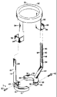
Referring to FIG. 1, it will be seen that a
preferred embodiment of theft-resistant assembly for
fluorescent lamps includes a first member 10, a second
member 30, and a third member 50.
The first member 10 is provided with a first
semi-annular ring portion 12 and a first arm portion
CA 02225767 1997-12-23
96-1-341 -10- PATENT APPLICATION
14. The ring~portion 12 is provided with first ring
connectors 15 thereon such as, for example, one or the
other, or both, of (1) a recess 16 and hole 18 in
communication therewith (FIG 3), and (2) a threaded
hole 20. The first ring connectors 15 further include
at least one screw 22 which is insertable through the
recess 16. The threaded hole 20 is adapted to receive
a screw similar to the screw 22. The first arm
portion 14 includes a first base portion 24 upstanding
from the first ring portion 12 and may be integral
with the ring portion 12, and a first locking arm
portion 26 which may be integral with the first base
portion 24. The first locking arm portion 26 is
provided with a first arm connector 28, to be
described hereinbelow.
Similarly, the second member 30 is provided with
a second semi-annular ring portion 32 and a second arm
portion 34. The ring portion 32 is provided with a
second ring connector 35 thereon such as one or the
other, or both, of (1) a recess 36 and hole 38 in
CA 02225767 1997-12-23
96-1-341 -11- PATENT APPLICATION
communication therewith, and (2) a threaded hole 40.
The second ring connector 35 further includes at least
one screw 42 which is insertable through the recess
36. The threaded hole 40 is adapted to receive the
screw 22 and the threaded hole 20 is adapted to
receive the screw 42. The second arm portion 34
includes a second base portion 44 upstanding from the
second ring portion 32 and may be integral with the
ring portion 32, and a second locking arm portion 46
which may be integral with the second base portion 44.
The second locking arm portion 46 is provided with a
second arm connector 48, to be described hereinbelow.
It will be apparent that the connectors 15, 35 on
the first and second ring portions 12, 32 may both be
threaded holes, as at 20, 40, or may both be recesses
and holes, as at 16, 18 and 36, 38. Thus, both screws
22, 42 may be introduced through one of the first and
second ring portions 12, 32 and received by the other,
to join the first and second members 10, 30 together.
CA 02225767 1997-12-23
96-1-341 -12- PATENT APPLICATION
The third -member 50 includes a collar portion 52,
a first leg portion 54 depending from the collar
portion 52, and a second leg portion 56 depending from
the collar portion 52. The first leg portion 54 is
provided with a first leg connector 58 and the second
leg portion 56 similarly is provided with a second leg
connector 60.
The above-described assembly is for use with a
screw base compact fluorescent lamp (shown in phantom
in FIG. 2) having one or more U-tubes 70 integrated
with and extending from an adapter member 72. The
adapter member is provided with a threaded portion 74
which engages with an internally threaded socket 76 of
the type generally found in incandescent lamps. The
lamp socket 76 is provided with a protrusion 75
including a tubular portion 77 which retains, as by a
set screw 79, a threaded portion 78 by which the
socket 76 is mounted on a lamp base 80, as by screwing
the protrusion portion 78 into a threaded hole in the
lamp base 80, or by extending the protrusion portion
CA 02225767 1997-12-23
96-1-341 -13- PATENT APPLICATION
78 through a hole in the lamp base 80 and locking the
protrusion portion 78 therein with a nut (not shown)
on the inside of the lamp base 80. The lamp described
immediately above is known in the art and is typical
of incandescent lamps and typical of lamps often
sought to be converted to fluorescent.
In using the theft resistant assembly herein, the
first and second ring portions 12, 32 are connected
together by the first and second ring connectors 15,
35, such as screws 22, 42 advanced through recesses
16, 36 and holes 18, 38 and into threaded holes 20, 40
respectively, to form a complete ring 82 (FIG. 3)
around the socket protrusion 75, thereby locking the
ring 82 between the socket 76 and the lamp base 80.
The collar portion 52 is then slipped over the one or
more U-tubes 70 and moved toward the lamp base 80.
Referring to FIG. 4, there is shown an enlarged
elevational, partly sectional view of the second arrn
connector 48 which comprises second arm tooth means 84
on a surface 86 of the second arm 34. The tooth means
CA 02225767 1997-12-23
96-1-341 -14- PATENT APPLICATION
84 comprises a series of teeth 88 disposed in a line
substantially axially of the socket 76, as shown in
FIG. 2. The second leg connector 60 comprises a tooth
90 (FIG. 4) movable along the line of teeth 88 in a
direction toward the lamp base 80, to move the collar
52 and ring 82 closer together. However, once the
collar 52 engages a top surface 92 of the adapter 72,
the tooth 90 cannot be moved in the opposite
direction. Thus, the second leg connector 60 and the
second arm connecter 48 are locked together.
Referring again to FIG. 4, it will be seen that
the second leg connector 60 comprises a four-sided
body 94 defining a passageway 96 therethrough. The
series of rachet-like teeth 88 is moveable through the
passageway 96 in one direction only.
The first leg connector 58 and first arm
connector 28 are substantially the same in
configuration and function as the second leg connector
60 and second arm connector 48. Thus, the locking arm
portions 26, 46, which are substantially parallel to
CA 02225767 1997-12-23
96-1-341 -15- PATENT APPLICATION
each other and- to the axis of the socket 76, lock to
the legs 54, 56 to lock the adapter member 72 and
socket 76 therebetween. The four-sided bodies 94
prevent easy separation of the tooth 90 and ratchet-
s like teeth 88. Upon completion of the locking
operation, the adapter member 72, having the U-tube 70
locked therein, is locked in place.
It will be appreciated that the teeth 88 could
just as well be placed on one or more of the arms 14,
34, and the tooth 90 on one or more of the legs 54,
56.
It is recognized that diligent work on the part
of a thief will, in due course, uncouple the first and
second locking arm portions 26, 46 from the third
member 50. It is further recognized that the legs 54,
56 or arms 14, 34 can be cut with heavy shears.
However, most light bulb pilferage occurs, in large
measure, because the removal of a light bulb is easy
and not time-consuming. By rendering the bulb removal
CA 02225767 1997-12-23
96-1-341 -16- PATENT APPLICATION
process more complicated and time-consuming, rampant
pilferage thereof is diminished substantially.
The application of the assembly herein is a
relatively simple mechanical operation and can be
performed by low-skill maintenance personnel. When
the time comes to remove and replace the bulb, an
operator unscrews the screws 22, 42 to separate the
ring portions 12, 32 from each other, to permit the
assembly to be lifted from the integrated bulb and
adapter combination, which may then be easily removed
and replaced. The assembly is then locked in place to
deter theft of the new bulb, all in a matter of
seconds.
The assembly preferably is of molded plastic and
molded in three parts, i.e., the first member 10,
second member 30, and third member 50. The first and
second members 10, 30 may be identical and therefore
produced in the same mold cavity. The cost for the
assembly is accordingly minimal.
CA 02225767 1997-12-23
96-1-341 -17- PATENT APPLICATION
There is thus provided a theft-resistant assembly
for the protection of fluorescent bulbs in
incandescent table lamps, and the like. The assembly
is inexpensive to manufacture and easily installed,
and does not require special provision for ballasts.
It is to be understood that the present invention
is by no means limited to the particular construction
herein disclosed and/or shown in the drawings, but
also comprises any modifications or equivalents within
the scope of the claims.