Language selection

Search

Patent 2226181 Summary

Third-party information liability

Some of the information on this Web page has been provided by external sources. The Government of Canada is not responsible for the accuracy, reliability or currency of the information supplied by external sources. Users wishing to rely upon this information should consult directly with the source of the information. Content provided by external sources is not subject to official languages, privacy and accessibility requirements.

Claims and Abstract availability

Any discrepancies in the text and image of the Claims and Abstract are due to differing posting times. Text of the Claims and Abstract are posted:

  • At the time the application is open to public inspection;
  • At the time of issue of the patent (grant).
(12) Patent Application: (11) CA 2226181
(54) English Title: ELECTRIC TOOTHBRUSH
(54) French Title: BROSSE A DENT ELECTRIQUE
Status: Deemed Abandoned and Beyond the Period of Reinstatement - Pending Response to Notice of Disregarded Communication
Bibliographic Data
(51) International Patent Classification (IPC):
  • A61C 17/34 (2006.01)
(72) Inventors :
  • HAHN, MATTHIAS (Germany)
  • HOFER, KLAUS (Germany)
  • RUHMKORFF, ANDREAS (Germany)
(73) Owners :
  • ROWENTA-WERKE GMBH
  • ROWENTA-WERKE GMBH
(71) Applicants :
  • ROWENTA-WERKE GMBH (Germany)
  • ROWENTA-WERKE GMBH (Germany)
(74) Agent: GOWLING WLG (CANADA) LLP
(74) Associate agent:
(45) Issued:
(22) Filed Date: 1998-01-05
(41) Open to Public Inspection: 1999-07-05
Examination requested: 2002-10-09
Availability of licence: N/A
Dedicated to the Public: N/A
(25) Language of filing: English

Patent Cooperation Treaty (PCT): No

(30) Application Priority Data: None

Abstracts

English Abstract


Electric toothbrush with a handle (1), a brush head (2) and
a shank (3) which connects the handle to the brush head,
and with a rotary motor (4) arranged in the handle which
drives an unbalanced mass (5). According to the invention
the unbalanced mass (5) driven by the motor (4) is
supported on one side or on both sides in the shank (3)
close to the brush head (2) and is driven via an extended
drive shaft, preferably an intermediate shaft (6), by the
motor (4).


Claims

Note: Claims are shown in the official language in which they were submitted.

6
Claims
1. Electric toothbrush with a handle (1), a brush head (2)
and a shank (3) which connects the handle to the brush
head, and with a rotary motor (4) arranged in the handle
which drives an unbalanced mass (5), characterised in that
the unbalanced mass (5) driven by the motor (4) is
supported on one side or on both sides in the shank (3)
and/or in the brush head (2) and is driven via an extended
drive shaft (6).
2. Electric toothbrush according to Claim 1, characterised
in that the unbalanced mass (5) supported in the shank (3)
is located as close as possible to the brush head (2).
3. Electric toothbrush according to Claim 1 or 2,
characterised in that the extended drive shaft consists of
an intermediate shaft (6) that is coupled on the motor side
to the shaft butt (41) of the motor (4) and is coupled on
the brush-head side to the shaft (51) of the unbalanced
mass (5).
4. Electric toothbrush according to Claim 1 or 2,
characterised in that the extended motor shaft consists of
an integral extension of the motor shaft that is coupled to
the shaft (51) of the unbalanced mass.
5. Electric toothbrush according to Claim 1 or 2,
characterised in that the extended drive shaft consists of
an integral extension of the shaft (51) of the unbalanced
mass that is coupled to the shaft butt (41) of the motor.
6. Electric toothbrush according to one of the preceding
claims, characterised in that the extended drive shaft
consists of flexible material.

7
7. Electric toothbrush according to one of the preceding
claims, characterised in that the couplings (7a, 7b) that
are present on the extended drive shaft are constructed
flexibly in such a way that the oscillations originating
from the unbalanced mass in the course of operation are
damped or decoupled in the direction towards the handle.
8. Electric toothbrush according to Claim 7, characterised
in that the couplings consist of short lengths (7a, 7b) of
tube or hose made of flexible material that adhere to the
ends of the shaft by friction.
9. Electric toothbrush according to one of the preceding
claims, characterised in that the shank (3) is constructed
on the handle side in such a way that it forms the foremost
part (1b) of the handle (1) and in that the motor (4) is
accommodated in this part (1b) of the handle (shank).
10. Electric toothbrush according to Claim 9,
characterised in that the connection between the handle
part (1b) that is formed by the shank (3) and the remaining
part of the handle is effected via damping connecting
elements, for example O-ring seals (8).
11. Electric toothbrush according to one of the preceding
claims, characterised in that the shank (3) is provided
with a point of separation near to the handle (1) but
still, viewed from the brush head, in front of the motor,
said point of separation permitting the brush head (2) to
be exchanged together with the greater part of the shank
(3), the extended drive shaft being partitioned at this
point of separation and provided with a coupling.

Description

Note: Descriptions are shown in the official language in which they were submitted.


CA 02226181 1998-07-08
Electric Toothbrush
The invention relates to an electric toothbrush according
to the preamble to Claim 1.
Electric toothbrushes consist of a handle, in which the
electric drive is accommodated, a brush head and a shank
connecting the brush head to the handle. Electric
toothbrushes are known in which the drive consists of a
rotary motor, on the shaft butt of which an unbalanced mass
is secured in self-supporting manner. This unbalanced mass
is located close to the motor in the handle. The
disadvantage of this design consists, on the one hand, in
that the handle is strongly influenced by the oscillations
(vibrations) generated by the unbalanced mass, which is
unpleasant for the user, and, on the other hand, in that
the influence of the unbalanced mass on the brush head is
relatively feeble. A further disadvantage consists in that
the motor is severely loaded by the unbalanced mass that is
arranged on its shaft in cantilevered manner, as a result
of which its lifespan is shortened.
The object underlying the invention is to develop an
electric toothbrush according to the preamble to Claim 1
that is largely freed from the aforementioned disadvantages
of an intense vibration of the handle, a poor transmission
of the vibrations to the brush head and a severe loading of
the motor.
With a view to achieving this object, an electric
toothbrush according to the preamble to Claim 1 is proposed
which, according to the invention, has the features
specified in the characterising portion of Claim 1.
Other configurations of the invention are specified in the
subclaims.

CA 02226181 1998-07-08
2
As a result of the displacement of the unbalanced mass to a
position near to or within the brush head, the vibrations
generated by the unbalanced mass are transmitted to the
brush head to a high degree, whereas they have little
effect on the handle.
The invention will be elucidated in more detail on the
basis of the embodiment example shown in the Figures.
Illustrated are:
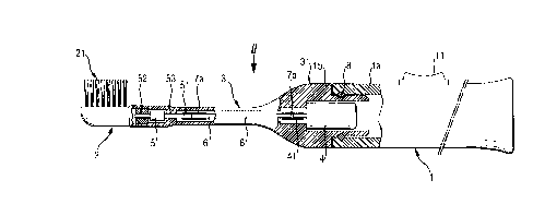
Figure 1 a side view of an example of an embodiment of an
electric toothbrush according to the invention,
partially in section,
Figure 2 a top view of the toothbrush acc. to arrow II in
Figure 1, partially in section.
In Figures 1 and 2 the handle that takes the form of a
casing is designated by 1, the brush head by 2 and the
shank connecting the brush head to the handle by 3. The
handle is formed substantially by the handle casing 1a. In
the embodiment example shown, the shank 3 is provided at
its end on the handle side with a section 31 that is
greatly enlarged in diameter (shank connecting piece) and
that forms the front part lb, located towards the brush
head, of the handle 1. The motor 4 is accommodated in this
enlarged shank connecting piece 31. The electrical lead,
which is not represented, to the motor is guided through
the handle 1 via the switch 11.
The unbalanced mass 5 is arranged at the end of the shank
on the brush-head side, close to the brush head 2. It is
provided with its own shaft 51 which is supported on both
sides in the bearings 52, 53. The drive shaft is extended
as far as the shaft 51 of the unbalanced mass, specifically
by means of an intermediate shaft 6 which connects the

CA 02226181 1998-07-08
3
motor-shaft butt 41 to the shaft 51 of the unbalanced mass.
The connections preferably consist of flexible couplings,
which in the embodiment example that is shown consist of
short lengths 7a, 7b of tube or hose that adhere to the
ends of the shaft by friction. The brush head 2 bearing
the array of bristles 21 is secured to the free end of the
shank in a known manner which is not represented, for
example by attachment by means of a clip fastener.
In the course of operation of the toothbrush the unbalanced
mass rotates, as a result of which the centrifugal force
arising leads to intense oscillations which have the
stronger effect at the brush head, the closer the
unbalanced mass is arranged to the brush head. Conversely,
these oscillations are largely damped or decoupled in the
direction towards the handle - to be specific, on the one
hand through the use of flexible couplings 7a, 7b and on
the other hand by virtue of the fact that the intermediate
shaft 6 is constructed from flexible material. A further
decoupling of the oscillations from the main part la of the
handle which is held by the hand of the user is obtained by
virtue of the arrangement of the motor in the enlarged
shank end 31 - to be specific, in particular by means of a
damping O-ring seal 8 arranged between the connecting
bearing surfaces pertaining to shank end 31 and main handle
part la.
In the embodiment example shown, the left-hand bearing of
the shaft 51 of the unbalanced mass is constituted by a
ring 52 that is inserted into the shank, whereas the
bearing 53 is constituted directly by parts of the inner
shank wall that are pulled forward in the direction towards
the centre line of the shank. Of course, the last-
mentioned bearing 53 may also consist of an inserted
bearing ring.

CA 02226181 1998-07-08
4
The embodiment example shown in the Figures may be varied
in many ways. The intermediate shaft 6 may be dispensed
with, either by the motor shaft being extended integrally
as far as the coupling 7a of the shaft of the unbalanced
mass or, conversely, by the shaft of the unbalanced mass
being extended integrally as far as the coupling 7b on the
shaft butt 41. In principle it is also possible for the
unbalanced mass 5 to be situated on a motor shaft that is
extended integrally as far as the brush head, said motor
shaft being additionally supported close to the brush head,
but this embodiment is not really suitable from the point
of view of manufacture.
Instead of being supported on two sides, as in the
embodiment example, the unbalanced mass may be supported on
one side only, on one side or the other.
With an appropriate design of the brush head the unbalanced
mass may be arranged in the brush head itself. It is also
possible for one of the bearings of the unbalanced mass to
be located in the brush head and for the other to be
located in the shank. In these cases, however, each of the
interchangeable brush heads has to be provided with an
unbalanced mass or a bearing pertaining to an unbalanced
mass. In these cases the shaft of the unbalanced mass is
moved out of one of the bearings when the brush head is
exchanged.
It is self-evident that the end of the shank on the handle
side may also be of different construction and may be
smaller in diameter, and that the motor may be arranged
further to the rear in the actual handle part la.
Finally it is also conceivable to provide the handle with a
point of separation near to the handle but to the left of
the motor in the sense of the drawing, said point of

CA 02226181 1998-07-08
separation permitting the brush head to be exchanged
together with the greater part of the shank. The extended
drive shaft is then partitioned at this point and provided
with a plug-in coupling similar to the coupling shown at 7a
5 in the Figures.

CA 02226181 1998-07-08
LIST OF REFERENCE SYMBOLS
1 handle
la handle casing
1b handle part
2 brush head
3 shank
4 motor
unbalanced mass
6 intermediate shaft
7a coupling
7b coupling
8 O-ring seal
11 switch
21 array of bristles
31 extended region
41 motor-shaft butt
51 shaft
52 bearing
53 bearing

Representative Drawing
A single figure which represents the drawing illustrating the invention.
Administrative Status

2024-08-01:As part of the Next Generation Patents (NGP) transition, the Canadian Patents Database (CPD) now contains a more detailed Event History, which replicates the Event Log of our new back-office solution.

Please note that "Inactive:" events refers to events no longer in use in our new back-office solution.

For a clearer understanding of the status of the application/patent presented on this page, the site Disclaimer , as well as the definitions for Patent , Event History , Maintenance Fee  and Payment History  should be consulted.

Event History

Description Date
Time Limit for Reversal Expired 2006-01-05
Application Not Reinstated by Deadline 2006-01-05
Deemed Abandoned - Failure to Respond to Maintenance Fee Notice 2005-01-05
Letter Sent 2002-11-07
Request for Examination Received 2002-10-09
Request for Examination Requirements Determined Compliant 2002-10-09
All Requirements for Examination Determined Compliant 2002-10-09
Inactive: Cover page published 1999-08-09
Application Published (Open to Public Inspection) 1999-07-05
Inactive: Single transfer 1998-07-08
Inactive: Correspondence - Formalities 1998-07-08
Inactive: IPC assigned 1998-04-29
Classification Modified 1998-04-29
Inactive: First IPC assigned 1998-04-29
Inactive: Filing certificate - No RFE (English) 1998-03-30
Application Received - Regular National 1998-03-28

Abandonment History

Abandonment Date Reason Reinstatement Date
2005-01-05

Maintenance Fee

The last payment was received on 2003-10-22

Note : If the full payment has not been received on or before the date indicated, a further fee may be required which may be one of the following

  • the reinstatement fee;
  • the late payment fee; or
  • additional fee to reverse deemed expiry.

Patent fees are adjusted on the 1st of January every year. The amounts above are the current amounts if received by December 31 of the current year.
Please refer to the CIPO Patent Fees web page to see all current fee amounts.

Fee History

Fee Type Anniversary Year Due Date Paid Date
Application fee - standard 1998-01-05
Registration of a document 1998-07-08
MF (application, 2nd anniv.) - standard 02 2000-01-05 1999-12-16
MF (application, 3rd anniv.) - standard 03 2001-01-05 2000-11-17
MF (application, 4th anniv.) - standard 04 2002-01-07 2001-09-05
Request for examination - standard 2002-10-09
MF (application, 5th anniv.) - standard 05 2003-01-06 2002-12-02
MF (application, 6th anniv.) - standard 06 2004-01-05 2003-10-22
Owners on Record

Note: Records showing the ownership history in alphabetical order.

Current Owners on Record
ROWENTA-WERKE GMBH
ROWENTA-WERKE GMBH
Past Owners on Record
ANDREAS RUHMKORFF
KLAUS HOFER
MATTHIAS HAHN
Past Owners that do not appear in the "Owners on Record" listing will appear in other documentation within the application.
Documents

To view selected files, please enter reCAPTCHA code :


To view images, click a link in the Document Description column. To download the documents, select one or more checkboxes in the first column and then click the "Download Selected in PDF format (Zip Archive)" or the "Download Selected as Single PDF" button.

List of published and non-published patent-specific documents on the CPD .

If you have any difficulty accessing content, you can call the Client Service Centre at 1-866-997-1936 or send them an e-mail at CIPO Client Service Centre.


Document
Description 
Date
(yyyy-mm-dd) 
Number of pages   Size of Image (KB) 
Representative drawing 1999-08-03 1 9
Abstract 1998-01-04 1 14
Description 1998-01-04 6 174
Claims 1998-01-04 2 70
Drawings 1998-01-04 1 24
Abstract 1998-07-07 1 13
Description 1998-07-07 6 188
Claims 1998-07-07 2 76
Drawings 1998-07-07 1 38
Filing Certificate (English) 1998-03-29 1 165
Courtesy - Certificate of registration (related document(s)) 1998-09-23 1 114
Reminder of maintenance fee due 1999-09-07 1 114
Reminder - Request for Examination 2002-09-08 1 116
Acknowledgement of Request for Examination 2002-11-06 1 176
Courtesy - Abandonment Letter (Maintenance Fee) 2005-03-01 1 174
Correspondence 1998-04-02 1 33
Correspondence 1998-07-07 11 357