Note: Descriptions are shown in the official language in which they were submitted.
CA 02226497 1998-O1-07
WO 97/43496 PCT/CA97/00305
Title of the invention
MODULAR FORMWORK FOR CONCRETE
s
Technical Field of the Invention
This invention relates to formwork for casting vertical concrete structures
such as
walls.
The forms of the invention are elongated modular elements which are adapted to
interconnect to one another along their longitudinal sides to create overall
formwork for
casting concrete to form a wall or other vertical structure.
Background Art
It is known in the prior art to provide modular farm elements which may be
zo stacked end to end and wherein a plurality of horizontal courses are
superposed one upon
the other to create a wall of formwork. Examples of such elements are
disclosed in
United States Patent 2,172,052 to Robbins and U.S. Patent 3,788,020 to
Gregori.
It is also known to provide modular form elements consisting of a plurality of
zs vertical and essentially closed forms which can be nested alongside one
another to create
a series of adjacent concrete columns. U.S. Patent 5,216,863 to Nessa et al.
discloses
. such elements having generally circular or octagonal cross sections. In
Nessa's
octagonal cross section embodiment, the cross section of the foam element
comprises the
general shape of an octagon with one side missing so as to create an open
side. The free
3o edges adjacent the open side are provided with retaining means which are
designed to
cooperate with complementary retaining means mounted on the back of an
adjacent
SUBSTITUTE SHEET (RULE 26)
CA 02226497 1998-O1-07
WO 97/43496 PCT/CA97/00305
2
element. A plurality of elements can thereby be secured to one another,
"piggyback"
style, to create a formwork of columns into which concrete can be poured.
s There are a number of desirable objectives in relation to modular form
elements.
Where it is intended to leave the form in place after casting the concrete, it
is desirable to
provide a form element which enables the easy application of wall finishes or
coverings
to the surface thereof. Other desirable features are the ability to allow the
concrete to
flow between interconnected form elements so as to provide strength and
rigidity to the
to concrete structure, the ability to insert reinforcing rods in the formwork
and the ability of
the formwork to be waterproof so as to prevent corrosion of reinforcing
elements
embedded in the concrete. It is also desirable in some cases for finished
formwork to
offer insulation properties.
~s Various prior art approaches achieve some of these objectives, but with
varying
success. For example, in the case of U.S. Patent 5,216,863 it is difficult to
provide
insulation or Iiner within the form, mainly because of the essentially closed
nature of the
octagonal or circular form, and the structure of the form tends to impede the
flow of
concrete between adjacent forms. Moreover, the resulting formwork lacks
structural
2o rigidity and when the formwork is filled with concrete, it suffers from a
'banana effect'
which causes the walls of the form elemenfs to bulge out. This lack of
rigidity in the
formwork makes it difficult to secure wall finishes and coverings.
- It is an object of this invention to provide a modular formwork assembly
which
2s overcomes the deficiencies of the prior art and which has improved
structural rigidity
when assembled so as to minimize bulging or a "banana effect" in the
structure.
SUBSTITUTE SHEET' (RULE 26)
CA 02226497 1999-07-07
3
Summar~r of the Invention
According to one of its aspects, the invention comprises a modular formwork
s assembly for casting concrete to form vertical structures, and a kit of its
component parts.
The assembly comprises a plurality of elongated elements, each having an
inside surface
extending from one longitudinal edge of the element to the opposite
longitudinal edge of
the element so as to define a generally concave cross section. The surface has
a generally
planar middle portion. 7,he element also comprises two extensions which extend
laterally
io outward from the middle portion and which are co-planar with the middle
portion. The
longitudinal edges and the edges of the extensions are provided with engaging
means
extending substantially Gong the length of the element for releasably
interconnecting the
element with a connecting member. Each of a plurality of elongated connecting
members
comprises an elongated wall defined between a first and an opposite
longitudinal edges
1 s of the member, a central portion defined between a first and an opposite
inner
longitudinal section lines of the member and having at least one opening
therein, two
outer portions each of which is defined between a longitudinal edge and an
inner
longitudinal section line of the member. Each of the longitudinal edges and
inner
longitudinal section linf;s of the member is provided with engaging means
adapted to
2o cooperate in longitudinal sliding engagement with the engaging means of
each of a pair
of said elements when the elements are presented in edge to edge relationship
for
connection about opposing sides of the engaging means of the member. The
connecting
member is adapted to engage simultaneously each of a first pair of elements
presented in
edge to edge relationship about one outer portion of the member and each of a
second
2s pair of elements presented in edge to edge relationship about the opposite
outer portion
of the member.
In another aspect of the invention, each elongated element has inward
projections
projecting inwardly from its inside surface whereby to anchor the element to
concrete
3o poured into the formwork created by interconnecting a plurality of
elongated elements.
CA 02226497 1999-07-07
3A
In another of its aspects, the elongated element has insulating material on
its inside
surface.
s In yet another of its aspects, the connecting member has a plurality of ribs
extending between its inner longitudinal section lines along the length of the
member and
being spaced a distance from one another su~cient to enable the flow of
concrete
through the openings between the ribs.
~o The resulting assembly provides a formwork which substantially maintains
its
shape when filled with concrete and which does not suffer from "banana
effect". The
spacing of ribs along the central portion of the connecting member provides
pathways for
the insertion into the formwork of reinforcing rods, and also allows the
integral formation
CA 02226497 1998-O1-07
WO 97/43496 PCT/CA97/00305
4
of horizontal lengths of concrete along the pathways formed by aligned spaces
between
the ribs of adjacent elements.
s By engaging a connecting member to an element, a triangular space is formed
Y
between the outer side of the element, the extension of the element and the
outer portion
of the connecting member. The triangular space provides increased rigidity to
the
formwork and serves as an insulator for the formwork wall.
1o Brief Description of the Drawings Embodiment
Other aspects of the invention will be evident from the following disclosure
and
description of the preferred embodiment and from the drawings in which:
~s Figure 1 is a schematic plan view of an assembly of formwork illustrating
connecting members and elements according to the invention;
Figure 2 is an end view of an element according to the preferred embodiment of
the invention;
Figure 3 is an end view of one embodiment of a connecting member according to
the invention;
Figure 4 is a front view of a length of the connecting member shown in Figure
3;
Figure 5 is an end view of another embodiment of a connecting member
according to the invention;
Figure 6 is a front view of a length of the connecting member of Figure 5;
Figure 7 is an end view of a cornering piece according to the invention;
SUBSTITUTE SHEET (RULE 26~
CA 02226497 1998-O1-07
WO 97/43496 PCT/CA97/00305
Figure 8 is a front view of a length of the cornering piece of Figure 7;
Figure 9 is an end view of an inside corner finishing piece according to the
5 invention;
Figure 10 is an end view of an angle piece according to one embodiment of the
invention; and
to Figure 11 is an end view of an element with anchors according to one
embodiment of the invention.
Detailed Description of the Best Mode and Preferred
is Embodiment of the Invention
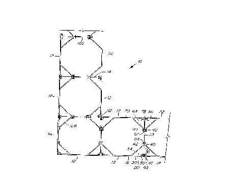
Figure 1 is a schematic plan view of an assembly IO of formwork illustrating a
plurality of elements 12 joined together by connecting members 14. A formwork
wall is
created by placing a course of elements adjacent one another in edge to edge
relationship,
2o as between elements 16 and 18, placing a second course of elements adjacent
one another
in edge to edge relationship, as between elements 20 and 22, and inter-
connecting the
elements by means of a connecting member, as in member 23.
Figure 2 is an end view of an element 12 according to the preferred embodiment
2s of the invention. The element 12 is preferably made of a material such as
polyvinylchloride as are the other components descl-ibed herein. The element
12 is
comprised of a generally concave elongated form and has a surface 24 which is
three
sided. The middle side or portion 26 of the element 12 is provided with two
extensions
28 and 30 which extend laterally along the plane of the middle side 26. The
longitudinal
3o edges 36 and 38 of the outer sides 32 and 34 are provided with engaging
means 40 and
42. The engaging means 40 and 42 of the outer sides 32 and 34 are in the shape
of the
SUBSTITUTE SHEET (RULE 26)
CA 02226497 1998-O1-07
WO 97/43496 PCT/CA97/00305
6
female portion of a T connector. The longitudinal edges 44 and 46 of the
extensions 28
and 30 are also provided with engaging means 48 and 50. The engaging means 48
and 50
of the extensions 28 and 3 0 are in the shape of the male portion of a T
connector.
The concavity of the element 12 allows easy access to the inside face 52 of
the
element for the placing or bonding of various types of insulation or Iiner
within the inside
face of the element prior to erection of the formwork or at the time of
manufacture of the
element 12. Foam type insulation may be used or a composite insulation or a
thinner
to liner may be bonded to the inner surface of the element I2. Alternatively,
the element 12
can be used without any insulation or liner.
One embodiment of a connecting member 14 according to the invention is
illustrated in Figures 3 and 4. The connecting member 14 comprises an
elongated wall
~s 53 with a central portion 56 between two outer portions 57 and 59. A series
of ribs 54
extend in the central portion S6 along the length of the connecting member
between the
inner longitudinal section Iines S 8 and 60. A series of spaces 55 is formed
between the
nibs 54 of the central portion 56. Engaging means 62 and 64 are provided along
each
inner Iine 58 and 60 of the connecting member 14. Engaging means 62 in turn
consists
20 of two male portions 66 and 68 of a T connector disposed opposite one
another in
relation to the central portion 56. Engaging means 64 in turn consists of two
male
portions 70 and 72 of a T connector disposed opposite one another in relation
to the
central portion 56. The outer longitudinal edges 74 and 76 of the connecting
member 14
- are also provided with engaging means 78 and 80. Engaging means 78 in turn
consists of
25 two female portions 82 and 84 of a T connector disposed opposite one
another in relation
to the central portion 56. Engaging means 80 in turn consists of two female
portions 86
and 88 of a T connector disposed opposite one another in relation to the
central portion
56.
so Each of the male portions of the T connector that form the inner Iine
engaging
means 62 and 64 of the connecting member 14 are sized to cooperate with the
female
suBSrrru~ sHEET (RUSE 26)
CA 02226497 1998-O1-07
WO 97/43496 PCT/CA97/00305
7
portions of the T connector which form the outer side engaging means 40 and 42
of the
element 12. Each of the female portions of the T connector that form the outer
edge
s engaging means 78 and 80 of the connecting member 14 are sized to cooperate
with the
male portions of the T connector which form the extension engaging means 48
and 50 of
the element 12.
Referring again to Figure 1, the engaging means 62, 64, 78 and 80 of
connecting
member 23 can be positioned in relation to engaging means 40, 42, 48~ and 50
of four
elements 16, 18, 20 and 22, then slid into engagement with them along the
length of the
connecting member 23 and of the elements 16, 18, 20, 22 (i.e. into the plane
of Figure i).
Connecting member 23 thereby acts as a spacer to hold elements 16 and 20 and
elements
18 and 22 a contr oiled distance apart from one another . This, as well as the
fact that the
is concrete can flow laterally through the spaces 55 of the connecting
members, prevents
the bulging outwar d of the interconnected elements once the concrete is
poured into the
formwork.
It will be appreciated that the connecting member 23 acts not only to hold the
2o facing elements 16 and 20 and elements 18 and 22 a certain distance from
one another,
but also to secure laterally adjacent elements 16 and 18 and elements 20 and
22 in edge
to edge relationship to one another.
By engaging connecting member 23 to element I6, a triangular space 90 is
formed
2s between the outer side 34 of element 16, the extension 30 of element 16 and
the outer
portion 59 of connecting member 23. Similar triangular spaces will be formed
each time
an element 12 is engaged to a connecting member 14. The triangular space 90
provides
r igidity to the formwork when the structure is filled with concrete and
prevents the
deformation at the lower parts of the formwork under the effect of the weight
of the
3o concrete. The triangular space 90 may also serve as an insulating space for
the formwork
wall. It is also contemplated by this invention that holes may be added to the
outer side
SUBSTITUTE SHEET (RULE 26)
CA 02226497 1998-O1-07
WO 97/43496 PCT/CA97/00305
8
34 of element 1 G thereby allowing concrete poured into the formwork to flow
into the
triangular space 90.
s Once one connecting member is slidingly engaged with a first set of four
elements,
another connecting member can be slid into engagement with the engaging means
on the
end of the elements opposite the connecting member which is already installed.
Thus a
wall of formwork is gradually erected. Since the engagement between the
connecting
members and the elements is a sliding one, the formwork or any given
connecting
to member can be disassembled easily, provided the concrete has not been
poured.
As noted above, connecting members 14 are provided with ribs S4. The spaces 55
between the ribs 54 are large enough to ensure a minimum of impedance to the
flow of
concrete through of the centr al portion 56. Reinforcing rods can be extended
along the
is lateral length of the wall through the spaces 55 of the central portion 56.
The reinforcing
rods may in fact be disposed in any orientation within the plane of the
concrete wall, with
the only limitation being the existence of a linear arrangement of spaces S5
in adjacent
members along the pathway to be followed by the reinforcing rod. Thus the rods
may be
asxanged either horizontally or diagonally according to the regularity and
spacing of the
2o ribs 54 in adjacent connecting members 14.
It is possible according to the invention to erect only one side or face of
the
formwork by connecting the connecting members 14 to a plurality of elements 12
but
leaving the opposite edge of the connecting members free. With appropriate
bracing of
2s the resulting structure it is then possible to install reinforcing rods in
the pathways
defined by the spaces 55 of successive connecting members. As only one side of
the
formwork will have been erected, the overall pattern of reinforcing rods is
visible from
the open side of the formwork allowing an evaluation of the suitability of the
reinforcing ,
scheme. Once the reinforcing rods are satisfactorily installed, the
complementary side of
3o the formwork may be erected by sliding a plurality of elements 12 into the
engaging
means on the free edges of the connecting members 14.
SUBSTITUTE SHEET (RULE 26~
CA 02226497 1998-O1-07
WO 97/43496 PCT/CA97/00305
9
Anchors 92 may also be provided which project inwardly of the surface 24 of
the
element I2 as shown in Figure 11 so as to engage the concrete after it is
poured and in
' order to provide additional rigidity to the structure.
s
Figures 7 and 8 illustrate a cornering piece 94 according to the invention.
The
cornering piece 94 comprises a substantially planar elongated wall 96. The
cornering
piece 94 is provided with two central engaging means 98 and 100 and engaging
means
102 and 104 at each Iongifudinal end. The central engaging means 98 and 100
are on one
o side of the wall 96 and consist of the male portions of a T connector. One
of the
longitudinal engaging means 102 is on the same side of the wall 96 as the
central
engaging means 98 and 100 and consists of the female portion of a T connector.
The
other longitudinal engaging means 104 consists of the male portion of a T
connector and
faces away from the plane of the cornering piece. Referring to Figure 1, the
corning
Is piece 94 is used negotiate the outer comer of a turn in the formwork wall.
A flat angle piece 106 having angled engaging means 108 and 110 as illustrated
in
Figure 10 may be used to negotiate corners and other changes in direction in
the wall
structure. The engaging means 108 and 1 i0 consists of the female portions of
a T
2o connector. Referring to Figure 1, the angle piece 106 is not only used to
negotiate the
corner, but also forms a triangular space similar to the one described herein.
Figure 9 is an end view of an inner corner finishing piece 112 according to
the
invention. The inner corner finishing piece 1 Z2 comprises two engaging means
114 and
2s I16 jointed together at a 90° angle. The engaging means 114 and l I6
consists of two
female portions of a T connector. Referring to Figure I, the inner corner f
nishing piece
112 is used negotiate the inner corner of a turn in the formwork wall.
r
It will be appreciated that var ious complementary components may also be used
in
3o association with the components described above but which have not been
described in
detail. Another embodiment of the element I18 may be created without the
extensions
SUBSTITUTE SHEET (RULE 26)
CA 02226497 1998-O1-07
WO 97/43496 PCT/CA97/00305
and is illustrated in Figure 1. Another embodiment of the connecting member
I20 is
illustrated by Figures 5 and G. Referring to Figure 1, by using the
alternative
embodiments of the elements 118 and connecting members 120, the formwork has
an '
s external appearance of a row of abutting columns.
While the engaging means of the preferred embodiment have been described in
some detail, variations on the specific structure of the engaging means may be
practised
within the scope of the invention, provided there is a sliding engagement
between the
to cooperating engaging means of the elements and the connecting members to
enable the
easy erection of the formwork.
It will be appreciated by those skilled in the art that other variations of
the
preferred embodiment may also be practised without departing from the scope of
the
is invention.
SUBSTITUTE SHEET (RULE 26~