Language selection

Search

Patent 2226697 Summary

Third-party information liability

Some of the information on this Web page has been provided by external sources. The Government of Canada is not responsible for the accuracy, reliability or currency of the information supplied by external sources. Users wishing to rely upon this information should consult directly with the source of the information. Content provided by external sources is not subject to official languages, privacy and accessibility requirements.

Claims and Abstract availability

Any discrepancies in the text and image of the Claims and Abstract are due to differing posting times. Text of the Claims and Abstract are posted:

  • At the time the application is open to public inspection;
  • At the time of issue of the patent (grant).
(12) Patent Application: (11) CA 2226697
(54) English Title: ROOFING KETTLE CONTROL APPARATUS
(54) French Title: DISPOSITIF DE COMMANDE DE CHAUDIERE EN TOITURE
Status: Deemed Abandoned and Beyond the Period of Reinstatement - Pending Response to Notice of Disregarded Communication
Bibliographic Data
(51) International Patent Classification (IPC):
  • E1C 19/02 (2006.01)
  • F23D 14/72 (2006.01)
  • F23N 5/02 (2006.01)
  • F23N 5/12 (2006.01)
  • F23N 5/20 (2006.01)
(72) Inventors :
  • BYRNE, BRIAN T. (United States of America)
(73) Owners :
  • GARLOCK EQUIPMENT COMPANY
(71) Applicants :
  • GARLOCK EQUIPMENT COMPANY (United States of America)
(74) Agent: SMART & BIGGAR LP
(74) Associate agent:
(45) Issued:
(22) Filed Date: 1998-01-12
(41) Open to Public Inspection: 1998-07-13
Availability of licence: N/A
Dedicated to the Public: N/A
(25) Language of filing: English

Patent Cooperation Treaty (PCT): No

(30) Application Priority Data:
Application No. Country/Territory Date
08/782,327 (United States of America) 1997-01-13

Abstracts

English Abstract


Roofing kettle apparatus for heating asphalt
includes a wheeled chassis mounting a vat and a
heating system for heating the vat. The heating
system includes a solenoid operated valve for
controlling the flow of fuel gas from a fuel gas
source to each of a pair of burner nozzles and a
igniter light assembly having an outlet adjacent the
outlet of a first combustion chamber. An igniter
generates a spark to ignite gas discharging from the
igniter assembly outlet. A flame sensor adjacent to
the first combustion chamber outlet end senses the
burning of fuel gas. The igniter light assembly has
a second outlet adjacent the second combustion
chamber outlet end. The ignition of fuel gas
discharging from the igniter assembly ignites the gas
discharging through the combustion chamber outlets.
The burners extend into the combustion chambers.
Electric controls include circuitry in the igniter
and a temperature controller to energize and
deenergize the valve and generate a spark a number of
times with a time delay between each energization and
deenergization to purge gas in the combustion
chambers in the event the flame sensor does not sense
a flame after the respective energization and to
control the range of temperatures to which the
material in the vat is heated.


French Abstract

Installation d'une chaudière en toiture pour chauffer de l'asphalte et comprenant un support de cuve monté sur roues ainsi qu'un système de chauffage de la cuve. Le système de chauffage comprend un robinet à solénoïde pour commander le débit de gaz de combustion provenant d'une source de combustible alimentant deux paires de brûleurs et un ensemble d'amorçage dont la sortie se trouve à proximité de la sortie de la première chambre de combustion. Un allumeur produit une étincelle pour enflammer les gaz qui s'échappent de l'ensemble d'amorçage. Un détecteur de flammes se trouvant à l'extrémité de la première chambre de combustion détecte la combustion du gaz. L'allumeur possède une seconde sortie située à proximité de la sortie de la seconde chambre de combustion. L'inflammation du gaz provenant de l'allumeur enflamme le gaz qui s'échappe des buses dans les chambres de combustion. Les brûleurs se prolongent dans les chambres de combustion. Les commandes électriques comprennent un circuit d'allumeur et un régulateur de température pour ouvrir et fermer le robinet, et pour produire un certain nombre d'étincelles au cas ou le détecteur de flammes ne détecterait pas la présence d'une flamme après une excitation respective, et pour contrôler la plage de température de chauffage du matériau dans la cuve.

Claims

Note: Claims are shown in the official language in which they were submitted.


12
WHAT IS CLAIMED IS:
1. Roofing kettle apparatus, comprising a
chassis, a vat mounted on the chassis for heating
asphalt and heating means mounted to the chassis to
heat asphalt in the vat, said heating means including
a combustion chamber means for having fuel gas burnt
therein to provide a hot gas mixture, said combustion
chamber means having an outlet end and an inlet end,
burner means adjacent to the combustion chamber inlet
end to discharge fuel gas into the combustion chamber
means for being combusted, igniter means for
generating a spark to ignite fuel gas in the
combustion chamber means, gas circulation means for
conveying the hot gas mixture from the combustion
chamber means to adjacent the vat for heating the
vat, a pressurizing source of fuel gas, solenoid
operated valve means operative between an energized
open condition to permit gas flow from the source to
the burner means and a deenergized closed condition
for blocking the flow of fuel gas from the fuel gas
source to the burner means, said valve means fluidly
connecting the fuel gas source to the burner means, a
flame sensor means mounted adjacent to the combustion
means outlet end for sensing the ions generated by
the burning of fuel gas and thereupon generating a
signal, an electric power source, and electric
control means interconnected between the igniter
means, the flame sensor and the solenoid operated
valve means for selectively operating the solenoid
valve means to its open position and within a
predetermined time delay, apply a current to the
igniter means to generate a spark and maintain the
valve means in its open position beyond a
predetermined time delay subsequent to the valve

13
means being operated to its open position only in the
event a flame is sensed by the flame sensor means and
deenergize the solenoid operated valve means in the
event no flame is sensed.
2. The kettle apparatus of claim 1 wherein the
chassis is mounted on wheels for movement from one
location to another.
3. The kettle apparatus of claim 1 wherein the
heating means includes an igniter light assembly
having an outlet adjacent to the igniter means to
have fuel gas discharging through the igniter light
assembly outlet ignited by the spark generated by the
igniter means and thereby ignite fuel gas discharging
through the combustion chamber means outlet and an
inlet fluidly connected to the solenoid valve means
to have fuel gas flowing thereinto only when the
solenoid valve means is energized.
4. The kettle apparatus of claim 1 wherein the
heating means includes second combustion chamber
means having an inlet end and an outlet end, second
burner means mounted adjacent to the second
combustion chamber means inlet end to discharge fuel
gas under high pressure into the second combustion
chamber means for being combusted to produce a hot
gas mixture, second gas circulation means for
conveying the hot gas mixture from the combustion
chamber means to adjacent to the vat for heating the
vat, a light assembly means fluidly connected to the
solenoid operated valve means for having fuel gas
flow therethrough from the valve means in its open
position to adjacent to the igniter means for being
ignited by the spark and thereby ignite the fuel gas
being discharged from the second combustion chamber
means outlet end.
5. The kettle apparatus of claim 4 wherein the
light assembly means has an inlet fluidly connected

14
to the solenoid operated valve means for having fuel
gas flow thereinto when the valve means is in its
open position, a first outlet adjacent to the first
combustion chamber means outlet end and a second
outlet adjacent to the second combustion chamber
means outlet end in a remotely spaced relationship to
the light assembly means first outlet, the light
assembly means outlets discharging fuel gas toward
the adjacent combustion chamber means outlet end when
fuel gas flows into the light assembly means inlet,
the igniter means includes an igniter having a spark
gap adjacent to the light assembly means first outlet
and the first combustion chamber means to provide a
spark to ignite fuel gas flowing through the light
assembly means first outlet and the flame sensor
being mounted adjacent to the first combustion
chamber means and in a remotely spaced relationship
to the second combustion chamber means outlet end.
6. The kettle apparatus of claim 5 wherein the
light assembly means comprises a T-shaped fitting
that has a cross tube having the light assembly means
outlets and a temperature sensor is mounted adjacent
to the vat for sensing the temperature of the asphalt
therein and the control means includes a temperature
controller electrically interconnected between the
power source, the temperature sensor and the igniter
means for acting in cooperation with the igniter
means to permit the igniter means energizing the
solenoid valve means when the temperature at the vat
means is below a preselected range and to deenergize
the solenoid valve means when the temperature is
within the preselected range.
7. The kettle apparatus of claim 1 wherein the
igniter means includes a spark igniter defining a
spark gap and a spark box having circuitry for
controlling the energization and deenergization of

15
the solenoid valve means and the generation of a
spark across the spark gap, the control means
includes a temperature sensor adjacent the vat to
sense the temperature in the vat, a temperature
controller having the temperature sensor operatively
connected thereto and being electrically connected
between the power source and the spark box to signal
the spark box to deenergize the solenoid operated
valve means when the vat is heated to a preselected
temperature and to energize the solenoid operated
valve means when the temperature in the vat falls
below a preselected temperature.
8. The kettle apparatus of claim 7 wherein the
spark box includes circuitry means for energizing the
solenoid operated valve means a second time after a
time delay to purge fuel gas from the combustion
chamber means and for activating the spark igniter to
generate a spark a second time in the event the
solenoid valve means had been deenergized as the
result of no flame being sensed by the flame sensor
means after the first energization of the solenoid
valve means.
9. The kettle apparatus of claim 8 wherein the
control means includes an on-off switch connected in
series between the power source and the temperature
controller that is movable between an "on" position
to energize the igniter means and the temperature
controller and an "off" position to deenergize the
igniter means and the temperature controller, and the
circuitry means and the flame sensor means coact to
deenergize the solenoid operated valve means the
second time in the event no flame is sensed by the
flame sensor means within a predetermined time delay
after the solenoid operated valve means is energized
the second time, and in the event the solenoid
operated valve means is deenergized the second time,

16
after another time delay for purging of fuel gas from
the combustion chamber, energizes the solenoid valve
means and activates a igniter means a third time, and
in the event no flame is sensed by the flame sensor
the third time, blocks further energization of the
solenoid operated valve means until the on-off switch
is manually moved to its "off" position and then to
its "on" position.
10. Roofing kettle apparatus, comprising a
chassis, a vat mounted on the chassis for heating
asphalt and heating means mounted to the chassis to
heat the asphalt in the chassis, said heating means
including a combustion chamber means for having fuel
gas burnt therein to provide a hot gas mixture, said
combustion chambers having an outlet end and an inlet
end, burner means adjacent to the combustion chamber
means inlet end to discharge fuel gas into the
combustion chamber means for being burnt, igniter
means for generating a spark, gas circulation means
for conveying the hot gas mixture from the combustion
chamber means to adjacent the vat for heating the
vat, a pressurized source of fuel, solenoid operated
valve means operative between an energized open
condition to permit gas flow from the source to the
burner means and a deenergized closed condition for
blocking the flow of fuel gas from the fuel gas
source to the burner means, a flame sensor mounted
adjacent to the combustion chamber means for sensing
the burning of fuel gas, a igniter assembly having an
outlet adjacent to the igniter means for having gas
discharging therethrough ignited by a spark and an
inlet fluidly connected to the solenoid valve means
for conducting fuel gas to the igniter light assembly
outlet when the solenoid valve means is energized, an
on-off switch manually movable between an "on"
position and an "off" position, and electric control

17
means interconnected between the on-off switch, the
igniter means, the solenoid valve means and the flame
sensor to, upon the on-off switch being moved to its
"on" position, energize the igniter means and
therethrough energize the solenoid valve means and
generate the spark to ignite the fuel gas at the
igniter assembly outlet and thereby ignite the fuel
gas at the combustion chamber means and, in the event
there is no sensing by the flame sensor of the fuel
gas being ignited within a predetermined time delay
after the valve means is first energized, deenergize
the solenoid valve means and, after a time delay from
the deenergizing of the solenoid valve means for
purging of fuel gas from the combustion chamber
means, repeat energizing the solenoid valve means and
generating the spark and deenergizing the solenoid
valve means a preselected number of times to ignite
the fuel gas, and if the fuel gas is not ignited
after each of said number of times with time delays
after each time the solenoid valve means is
deenergized and before the solenoid valve means is
again energized, retaining the solenoid valve means
in a deenergized condition until the on-off switch is
turned "off" and then moved to its "on" position.
11. The kettle apparatus of claim 10 wherein
the control means includes a temperature sensor
mounted adjacent to the vat for sensing the
temperature of the asphalt in the vat and a
temperature controller electrically connected between
the on-off switch and the igniter means for, when the
on-off switch is in its "on" position, signaling the
igniter means to energize the solenoid valve means
when the temperature sensor senses the vat
temperature has fallen from a temperature within a
preselected temperature range to a temperature being
below said temperature range.

18
12. The kettle apparatus of claim 11 wherein
the electric control means includes an electric power
source and the on-off switch is connected in series
between the temperature controller and the electric
power source and the heating means includes a second
combustion chamber means having an inlet end and an
outlet end, second burner means mounted adjacent to
the second combustion chamber means inlet end to
discharge fuel gas under high pressure into the
second combustion chamber means for being burnt to
produce a hot gas mixture, second gas circulation
means for conveying the hot gas mixture from the
second combustion chamber means to adjacent to the
vat for heating the vat, the igniter light assembly
including a second outlet adjacent to the second
combustion chamber means outlet end for igniting fuel
gas being discharged therethrough and the spark
generated adjacent to the igniter light assembly
first outlet and the flame sensor located adjacent to
the first combustion chamber means outlet end and
remote from the second igniter light assembly outlet
and the second combustion chamber means outlet end.
13. The kettle apparatus of claim 11 wherein
the heating means includes a source of fuel gas under
high pressure, a first pressure regulator is fluidly
connected between the solenoid valve means and the
burner means and a second pressure regulator is
fluidly connected between the solenoid valve means
and the igniter light assembly inlet to apply fuel
gas to the igniter light assembly at a much lower
pressure than is applied to the burner means.
14. Roofing kettle apparatus, comprising a
chassis, a vat mounted on the chassis for heating
asphalt and heating means mounted to the chassis to
heat material in the vat, said heating means
including a combustion chamber means for having fuel

19
gas burnt therein to provide a hot gas mixture, said
combustion chamber means having an outlet end and an
inlet end, burner means adjacent to the combustion
chamber means inlet end to discharge fuel gas into
the combustion chamber means for being combusted, an
igniter light assembly having an inlet and a first
outlet to discharge fuel gas adjacent to the
combustion chamber outlet end for, when ignited,
igniting the fuel gas discharging from the combustion
chamber means outlet end, igniter means for
generating a spark to ignite fuel gas discharging
from the igniter light assembly outlet, gas
circulation means for conducting the hot gas mixture
from the combustion chamber means to adjacent the vat
for heating the vat, a high pressure source of fuel
gas, a high pressure regulator having an inlet and an
outlet for discharging fuel gas under high pressure,
conduit means for fluidly connecting the high
pressure regulator outlet to the burner means, a low
pressure regulator having an inlet and an outlet
fluidly connected to the igniter light assembly inlet
for conducting fuel gas thereto at a much lower
pressure than the pressure of the fuel gas conducted
to the burner means, solenoid operated valve means
operative between an energized open condition to
permit flow of fuel gas from the high pressure source
to the conduit means and the low pressure regulator
inlet and a deenergized closed condition for blocking
the flow of fuel gas from the high pressure fuel gas
source to the high and low pressure regulators,
sensor means mounted adjacent to the combustion
chamber means outlet end for sensing gases being
burnt at the combustion chamber means outlet end and
thereupon generating a signal, an electric power
source, and electric control means interconnected
between the igniter means, sensor means and the

solenoid operated valve means for operating the
solenoid operated valve means to its open condition
and within a predetermined delay, apply a current to
the igniter means to generate the spark to ignite the
fuel gas discharging from the igniter light assembly
outlet and maintaining the solenoid operated valve
means in its open condition for a sufficient period
of time for the ignited fuel gas at the igniter light
assembly outlet to ignite the fuel gas discharging
from the combustion chamber means outlet end.
15. The kettle apparatus of claim 14 wherein
the heating means includes a second combustion
chamber means having an inlet end and an outlet end,
second burner means mounted adjacent to the second
combustion chamber means inlet end to discharge fuel
gas under high pressure into the second combustion
chamber means for being burnt to produce a hot gas
mixture, the second burner means being fluidly
connected to one of the high pressure regulator and
the conduit means, second gas circulation means for
conducting the hot gas mixture from the second
combustion chamber means to adjacent the vat for
heating the vat, the igniter light assembly having a
second outlet remote from the igniter light assembly
first outlet and adjacent to the second combustion
chamber outlet end to ignite the fuel gas discharging
from the second combustion chamber means outlet end
when the fuel gas discharging from the igniter light
assembly first outlet is ignited.

Description

Note: Descriptions are shown in the official language in which they were submitted.


CA 02226697 1998-01-12
ROOFING KETTLE CONTROL APPARATUS
(1) Field of the invention
This invention relates to roofing kettles, and
S particularly to a control system for controlling the
heating of roofing material such as asphalt in
roofing kettles.
~2) Description of the prior art
In U.S. Patent No . 5,575,272 to Byrne, there is
discloced a kettle housing mounted on a wheeled
chassis together with a control system for
controlling the temperature in the asphalt vat. The
control system includes a spark igniter and a
thermocouple that emits an activation signal when
fuel gas has been ignited and significant heat is
being produced. Further, the control system includes
controls for starting and stopping the flow of gas
for maintaining the temperature of asphalt within a
desired temperature range.
U.S. Patent No. 4,416,614 to Moody discloses an
asphalt heating kettle wherein an electric igniter is
disposed in front of a pilot burner with the pilot
burner being opposite the main burner from the burner
flue. A thermocouple is provided to sense the
presence of a pilot flame and in the absence of a
flame, gas flow to the pilot burner and main burner
is turned off.
In roofing kettles using thermocouples of the
type that sense heat and that directly or indirectly
control the flow of fuel gas to the combustion
chambers, in the event the flame in the combustion
chamber should go out and the temperature in the vat
is below the range of the desired operating range of
temperatures that the material in the vat is to be
kept, the loss of heat adjacent to the combustion
chambers may not be sufficiently fast to stop the

CA 02226697 1998-01-12
flow oE fuel gas to the burner nozzles before a
considerable amount of unburnt fuel gas is discharged
into the kettle housing. This is undesirable.
In order to provide an improved control system
for roofing kettles, for example, ones such as
disclosed in the above patents, this invention has
been made.
SUMMARY OF T~IE INVENTION
The present ir-vention relates to a control
system for controlliny the flow of fuel gas frorn a
solenoid operated control valve that is operable
between an "on" position to start the flow of fuel
gas to a pair of burners and an igniter light
assembly at the same time and an "off" position to
stop such flow. The igniter light assembly includes
a T-shaped fitting having an inlet and outlets
adjacent to the respective one of the pair of
combustion chamber outlet ends. A spark igniter is
mounted adjacent to one of the combustion chambers
and one of the igniter light assembly fitting outlets
to ignite gas that is being discharged from the
igniter light assembly cross tube which in turn
ignites the fuel gas being discharged into the
adjacent combustion chamber from a fuel nozzle. A
flame sensor is mounted adjacent the outlet of a
combustion chamber to sense the ions generated by the
burnin~ gas. Upon the control system being actuated,
the control system automatically operates the igniter
and the fuel gas control valve to supply gas to the
igniter light assembly and to make up to three
attempts to ignite the gas flowing into the
combustion chamber with appropriate delays between
each attempt be~ore requiring the operator to restart
the process for starting the heating operation.

CA 02226697 1998-01-12
One of the objects of this invention is to
provide new and novel control means for sensing the
presence of a fLame at the outlet of a roofing kettle
combustion chamber and in the event such a flame is
not sensed within a preset time delay, discontinue
the supply of fuel gas to the combustion chamber and
igniter light assembly. Another object of this
invention is to provide in control means for a
roofing kettle, new and novel means, that upon
initially operating the controls to start heating the
kettle, will provide an ignition spark and fuel gas
at the kettle combustion chamber for up to a
preselected number of times, with a time delay
between each attempt for purging of fuel gas in the
chamber between each attempt in the event the fuel
gas is not ignited, before the operator has to
restart the ignition procedure.
BRIEF DESCRIPTION OF THE DRAWINGS
Figure 1 is a somewhat diagrammatic side view of
a portable roofing kettle apparatus;
Figures 2A and 2B are a somewhat diagrammatic
showing of the heating system for the roofing kettle
apparatus of Figure 1 with various parts being broken
awayi and
Figure 3 is a schematic showing of the control
system for regulating the flow of fuel gas to the
heating system and igniting the flue gas.
DETAILED DESCRIPTION
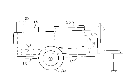
The roofing kettle apparatus of Figure 1,
generally designated 10, may be of the general type
disclosed in U.S. Patent No. 5,575,272 other than for
the modification of controls, including the location
and type of the igniter 11 and the flame sensor 12.

CA 02226697 l998-0l-l2
The kettle apparatus 10 includes a wheeled chassis 13
with wheels 13A mounting a kettle housing 14 and with
a hitch 15 for being attached to the chassis to
facilitate towing the kettle apparatus from place to
place.
Within the kettle housing, there is provided a
vat 17 for containing asphalt that is to be heated,
an open top well 18 in which the two main burner
nozzles 19 and combustion chambers 20 and 29 are
located and fuel arrays 21 through which the hot
combustion gases from the combustion chambers are
circulated to heat the material in the vat prior to
the combustion gases being discharged to the ambient
atmosphere through the flues 22. The inlet ends of
lS the futl arrays are adjacent to the outlet ends 20A
and 24E~ respectively of the combustion chambers. A
cover 23 is provided for selectively closing the open
top vat:.
The fuel array includes a series of pipes, only
partially shown, that extend in relationship to the
vat for heating the material therein. To provide
heated gases, a source of pressurized fuel gas 27,
for example LP gas in cylinders, is fluidly
connect;ed through a shutoff cock 28 and thence
through a filter 31 to a solent~id operated control
valve :30 that, when its solenoid coil 71 is
energized, is operated to an "open" position to
permit the fuel gas to flow therethrough, and when
deenergized, returns to its normally closed position
to block the flow of fuel gas therethrough. The
solenoid valve in turn is fluidly connected by a line
32 to the inlet end of the T-joint while one outlet
end of the joint is connected through fittings 37 to
a high pressure regulator 29. The outlet of
regulator 29 is fluidly connected to the inlet end of
the T-joint 41. The outlet ends of joint 41 are

CA 02226697 1998-01-12
fluidl~ connected by lines 77 and 78 to burner
nozzles 19. A shutoff valve 79 is provided in each
of the lines 77 and 78.
The burner nozzles extend adjacent to the
inlet ends of the combustion chambers or into the
combust:ion chambers 20 and 24 whereby, as fuel gas is
discharged under high pressure from the nozzles, the
fuel gas is mixed with air. The bracket 35, which
mounts the combustion chambers, is mounted to and
within the kettle housing.
When the fuel gas air mixture in the combustion
chambers is ignited, the hot gases are discharged
into the inlet ends of the adjacent fuel arrays 21.
The hot. gases in the fuel arrays circulate through
and/or adjacent to the vat to heat and/or maintain
the asphalt in a heated condition within a desired
temperature range. To ignite the fuel gas in the
combust:ion chambers, an igniter light assembly P has
opposit:e outlet ends 40A and 40B of the cross bar 40
of the T-fitting T opening adjacent to the discharge
ends 29A and 20A respectively of the combustion
chambers while the spark igniter 11 is mounted to
bracket. 35 to ignite the fuel gas discharging from
the out.let end 4OA. The spark igniter has two
opposed electric leads which are spaced apart to form
a spark gap llA to produce a spark when an electric
current. is applied to the spark igniter from the
spark box 43. When fuel gas is discharging from the
cross bar adjacent to combustion chamber 29 and is
ignitecl, a flame flashes through the cross tube to
ignite the fuel gas mixture discharging from outlet
40B to ignite the gas discharging from combustion
chamber 20.
To provide fuel gas to the cross tube 40, a
second outlet of the T-joint 33 is fluidly connected
to the inlet of a low pressure regulator 80 while

CA 02226697 1998-01-12
the regular outlet is fluidly connected by a conduit
81 to the inlet end 34 of the T-shaped fitting T.
Usually the pressure regulators are adjusted to apply
fuel gas at the nozzle burners under a much higher
pressure than the pressure of the gas applied to the
igniter light assembly, for example about 24-35 psi
to the burners and up to about 10 psi at the igniter
light assembly. To sense when the fuel gas air
mixture in combustion chamber 24 has been ignited,
the flame sensor 12 is mounted by a bracket 38 to
bracket 35 to be adjacent to the discharge end of
combustion chamber 24. The flame sensor, in
conjunction with a circuit (not shown) in the
temperature controller 47, is of a conventional type
that senses the presence of the light of a flame
through a process known as flame rectification as
contrasted to sensing heat. The flame sensor and
temperature controller are of conventional designs,
for example ones manufactured by Kidde-Fenwal, Inc.
and Robertshaw, Inc. respectively.
Eor conducting current to produce a spark at
the igniter spark gap llA, a lead 42 electrically
connects the spark igniter to a spark box 43 in the
igniter box B. The spark igniter may be of a
conventional type, for example one manufactured by
Kidde-Fenwal, Inc.. The igniter box B and the
controller box C are mounted to the exterior of the
kettle housing in a convenient location such as shown
in Figure 1.
The circuitry (not shown) in the spark box is
connected by a lead 44 to a terminal 45 of an
adjustable temperature controller 47 in the
controller box C while a manually operated on-off
switch 48 and a fuse 49 are connected in series
across a second terminal 51 of the temperature

CA 02226697 l998-0l-l2
controller and a terminal 53 of the battery 52. The
second battery terminal is connected to ground. At
least one thermocouple 54, which is connected to the
controller, is positioned in, or adjacent to, the vat
to sense the temperature of the asphalt in the vat.
The temperature controller 47 includes a control knob
50 that is rotatable for selectively varying the
desired temperature to which the vat material is to
be heated. Suitable indicia 57 iS provided adjacent
to knob 50 to indicate the selected operating
temperature of the vat.
- A blue "ready" light 55 iS connected to terminal
45 to be illuminated for indicating fuel gas is
burning or should be burning at the burners while a
green power light 58 iS connected to switch 48 for
being illuminated when the power switch 50 is in its
"on" position.
A lead 59 electrically connects the flame sensor
12 to t:he spark box 43 while a lead 70 iS connected
across the solenoid coil 71 of the solenoid valve 30
and the spark box to control the energization of the
solenoid coil 71 which in turn controls the flow of
fuel gas between the source 27 and the burner nozzles
and the igniter light assembly, provided the stop
cock and the shutoff valves 79 are open.
With cold asphalt in the vat and the stop cock
28 and shutoff valves 79 in an open condition, the
switch 48 is turned to its "on" position to apply
power t:o the spark box 43 and the temperature
contro]ler. The spark box contains internal
circuit:ry (not shown) for energizing the solenoid
coil 7] to operate the solenoid valve 30 to its open
condition and, with a time delay of a few seconds,
for example about four seconds, for fuel gas to flow
to the igniter light assembly and the outlet ends of
the cornbustion chamber, apply a current to the spark

igniter 11 to produce a spark at a spark gap 11~.
This ignites the fuel gas mixture at the outlet ends
of the cross tube 90 and the flame at the outlet ends
in turn ignite the fuel gas being discharged at the
outlet ends of the combustion chambers. Upon the
flame sensor 12 being activated by sensing the ions
generated by the burr-ing of fuel gas in combustion
charnber 24, a signal is sent to the temperature
controller and the spark box to indicate the fuel gas
mixture is ignited. The ignition of fuel gas
discharging from the igniter light assembly does not
activate the flame sensor and the generation of a
spark by the spark igniter does not ignite the fuel
gas being discharged from combustion chamber 24.
Thus, outlet 40A is sufficiently spaced from the
outlet of the combustion chamber 24 so that fuel gas
discharging from the combustion chamber does not blow
out the flame at the outlet 40A, but the flame at
outlet 40A will igrlite the fuel gas discharging from
the combustion chamber 24.
The spark box circuitry then retains the
solenoid valve 30 in its energized condition until
the thermocouple 54 acting through the temperature
controller sends a signal to the spark box for
deenergizing the solenoid coil 71, or the flame
sensor, no longer sensing a flame at the combustion
chamber 24, acts through the spark box circuitry to
deenergize the solenoid coil. This results in the
discon~inuance of fuel gas flow to t}le igniter light
assembly and the b~rner nozzles.
Upon the thermocouple sensing that the
temperature of the asphalt has fallen below the

CA 02226697 1998-01-12
preselected temperature range, a circuit (not shown)
in the ~emperature controller sends a signal to the
spark box to energize the solenoid coil again and
provide spark at the spark gap in the manner
'j described with reference to the initial ignition of
the fue.L gas mixture that is then exiting from the
combust.ion chambers.
In the event that a spark is provided at the
spark gap llA and the flame sensor does not sense the
1() existence of a flame at combustion chamber 24 upon
the end of a preset time delay in the spark box
circuit, the spark box opens a circuit to deenergize
the solenoid valve and thereby discontinue the supply
of fuel gas to the igniter light assembly and the
burner nozzles. Then, the spark box circuitry
provides a sufficient time delay for the fuel gases
in the ,~ombustion chambers to self purge and thence
automatically reenergizes the solenoid valve whereby
fuel ga.s is again supplied to the combustion chambers
2() and the inlet of the igniter light assembly. When
fuel gas is again being supplied, the spark box
completes a circuit to generate a spark at the spark
gap llA. If the gas mixture in the combustion
chamber.s is ignited such as sensed by the flame
sensor, the solenoid valve remains in its open
conditivn until the temperature sensor senses the
temperature in the vat is at the top end of or within
the des.ired temperature range.
In the event the flame sensor does not sense a
3() flame w.ithin a predetermined time, for example about
10 seconds, after the on-off switch is manually moved
to its '''on" position, the solenoid valve has been
energized (operated to its open position) and a spark
has been generated at the spark gap llA, the spark
box circuitry deenergizes the solenoid valve for a

CA 02226697 1998-01-12
predetermined time which is sufficient for fuel gas
to self purge from the combustion chambers.
Then the spark box circuitry automatically
energizes the solenoid valve a second time and
5 generates a spark such as above set forth.
If -the fuel gas air mixture in combustion chamber
24 is not ignited after the second attempt, the
series of occurrences referred to in the preceding
paragraph are automatically repeated. However, if
1() ignition of fuel gas does not take place ~not sensed
by the flame sensor) after the third attempt, the
spark box circuitry will not initiate a further
attempt to cause ignition until the on-off switch is
turned to its "off" position and again turned to its
"on" position. This provides a safety feature.
By using a flame sensor 12, in the event the
flame at combustion chamber 24 should go out, the
supply of fuel gas to the combustion chambers would
be discontinued in that the solenoid valve is
deenergized. When the temperature is sensed by a
temperature sensor, there may be a considerable time
delay before the solenoid valve is deenergized as
there may be a delay in the temperature adjacent the
temperature sensor dropping sufficiently that the
circuitry reacts to discontinue the supply of fuel
gas to the combustion chambers.
In the event it is desired to have combustion
take place in only one combustion chamber, only the
shutoff valve 79 in line 77 is opened prior to moving
the on-off switch to its "on" position.
It is to be understood that the control means may
include additional thermocouples and circuitry (not
shown), for example to sense the temperature in the
vat rising close to or beyond a safe level and act
through circuitry in the temperature controller and
the spark box to stop the flow of flue gas to the

CA 02226697 1998-01-12
11
fuel nozzles such as disclosed in U.S. Patent
5,575,272.

Representative Drawing
A single figure which represents the drawing illustrating the invention.
Administrative Status

2024-08-01:As part of the Next Generation Patents (NGP) transition, the Canadian Patents Database (CPD) now contains a more detailed Event History, which replicates the Event Log of our new back-office solution.

Please note that "Inactive:" events refers to events no longer in use in our new back-office solution.

For a clearer understanding of the status of the application/patent presented on this page, the site Disclaimer , as well as the definitions for Patent , Event History , Maintenance Fee  and Payment History  should be consulted.

Event History

Description Date
Inactive: Agents merged 2013-08-13
Inactive: IPC from MCD 2006-03-12
Time Limit for Reversal Expired 2004-01-12
Application Not Reinstated by Deadline 2004-01-12
Deemed Abandoned - Failure to Respond to Maintenance Fee Notice 2003-01-13
Inactive: Abandon-RFE+Late fee unpaid-Correspondence sent 2003-01-13
Letter Sent 2002-01-28
Reinstatement Requirements Deemed Compliant for All Abandonment Reasons 2002-01-14
Deemed Abandoned - Failure to Respond to Maintenance Fee Notice 2001-01-12
Application Published (Open to Public Inspection) 1998-07-13
Classification Modified 1998-05-14
Inactive: First IPC assigned 1998-05-14
Inactive: IPC assigned 1998-05-14
Inactive: Filing certificate - No RFE (English) 1998-04-06
Application Received - Regular National 1998-04-03

Abandonment History

Abandonment Date Reason Reinstatement Date
2003-01-13
2001-01-12

Maintenance Fee

The last payment was received on 2002-01-14

Note : If the full payment has not been received on or before the date indicated, a further fee may be required which may be one of the following

  • the reinstatement fee;
  • the late payment fee; or
  • additional fee to reverse deemed expiry.

Patent fees are adjusted on the 1st of January every year. The amounts above are the current amounts if received by December 31 of the current year.
Please refer to the CIPO Patent Fees web page to see all current fee amounts.

Fee History

Fee Type Anniversary Year Due Date Paid Date
Application fee - standard 1998-01-12
Registration of a document 1998-01-12
MF (application, 2nd anniv.) - standard 02 2000-01-12 1999-12-07
MF (application, 3rd anniv.) - standard 03 2001-01-12 2002-01-14
MF (application, 4th anniv.) - standard 04 2002-01-14 2002-01-14
Reinstatement 2002-01-14
Owners on Record

Note: Records showing the ownership history in alphabetical order.

Current Owners on Record
GARLOCK EQUIPMENT COMPANY
Past Owners on Record
BRIAN T. BYRNE
Past Owners that do not appear in the "Owners on Record" listing will appear in other documentation within the application.
Documents

To view selected files, please enter reCAPTCHA code :


To view images, click a link in the Document Description column (Temporarily unavailable). To download the documents, select one or more checkboxes in the first column and then click the "Download Selected in PDF format (Zip Archive)" or the "Download Selected as Single PDF" button.

List of published and non-published patent-specific documents on the CPD .

If you have any difficulty accessing content, you can call the Client Service Centre at 1-866-997-1936 or send them an e-mail at CIPO Client Service Centre.


Document
Description 
Date
(yyyy-mm-dd) 
Number of pages   Size of Image (KB) 
Representative drawing 1998-07-16 1 5
Description 1998-01-11 11 420
Abstract 1998-01-11 1 35
Claims 1998-01-11 9 400
Drawings 1998-01-11 4 60
Cover Page 1998-07-16 2 72
Courtesy - Certificate of registration (related document(s)) 1998-04-05 1 118
Filing Certificate (English) 1998-04-05 1 165
Reminder of maintenance fee due 1999-09-13 1 114
Courtesy - Abandonment Letter (Maintenance Fee) 2001-02-11 1 182
Notice of Reinstatement 2002-01-27 1 172
Reminder - Request for Examination 2002-09-15 1 116
Courtesy - Abandonment Letter (Maintenance Fee) 2003-02-09 1 176
Courtesy - Abandonment Letter (Request for Examination) 2003-03-23 1 167
Fees 2002-01-13 1 57
Fees 2002-01-13 1 37
Fees 1999-12-06 1 33