Language selection

Search

Patent 2226875 Summary

Third-party information liability

Some of the information on this Web page has been provided by external sources. The Government of Canada is not responsible for the accuracy, reliability or currency of the information supplied by external sources. Users wishing to rely upon this information should consult directly with the source of the information. Content provided by external sources is not subject to official languages, privacy and accessibility requirements.

Claims and Abstract availability

Any discrepancies in the text and image of the Claims and Abstract are due to differing posting times. Text of the Claims and Abstract are posted:

  • At the time the application is open to public inspection;
  • At the time of issue of the patent (grant).
(12) Patent: (11) CA 2226875
(54) English Title: HEATING ARRANGEMENT
(54) French Title: DISPOSITIF DE CHAUFFAGE
Status: Term Expired - Post Grant Beyond Limit
Bibliographic Data
(51) International Patent Classification (IPC):
  • F02M 25/06 (2016.01)
  • F01M 13/02 (2006.01)
  • F16K 49/00 (2006.01)
(72) Inventors :
  • BUTZ, THOMAS (Germany)
  • HOLCH, HANS-WERNER (Germany)
  • MUELLER, HEINZ (Germany)
(73) Owners :
  • FILTERWERK MANN & HUMMEL GMBH
(71) Applicants :
  • FILTERWERK MANN & HUMMEL GMBH (Germany)
(74) Agent: NORTON ROSE FULBRIGHT CANADA LLP/S.E.N.C.R.L., S.R.L.
(74) Associate agent:
(45) Issued: 2007-01-09
(86) PCT Filing Date: 1996-05-11
(87) Open to Public Inspection: 1997-01-30
Examination requested: 2003-05-09
Availability of licence: N/A
Dedicated to the Public: N/A
(25) Language of filing: English

Patent Cooperation Treaty (PCT): Yes
(86) PCT Filing Number: PCT/EP1996/002033
(87) International Publication Number: EP1996002033
(85) National Entry: 1998-01-14

(30) Application Priority Data:
Application No. Country/Territory Date
195 25 542.9 (Germany) 1995-07-13

Abstracts

English Abstract


A heating arrangement, particularly for preventing freezing of pipes for
delivering crankcase gas from the crankcase of an internal combustion engine
to the
air intake, in which a valve (12, 18) is provided which includes at least one
metal
plate, and a PTC thermistor (20) or a resistance heater is disposed on the
metal
plate.


French Abstract

L'invention concerne un dispositif de chauffage, servant notamment à éviter le gel de conduites servant à acheminer des gaz du carter-moteur depuis le carter d'un moteur à combustion interne jusqu'à la zone d'admission. Une soupape (12,18) présente au moins une plaque métallique sur laquelle est disposée une résistance à coefficient de température positif (20) ou un élément de chauffage par effet Joule.

Claims

Note: Claims are shown in the official language in which they were submitted.

Claims:
1. A heating arrangement for preventing freezing or icing of a duct for
carrying
crankcase gases from the crankcase of an internal combustion engine to the air
intake,
wherein an element is provided for warming the crankcase gases, said element
comprising a valve which comprises at least one metal plate and a cold
conductor on
said plate, said cold conductor being provided with a plug contact for feeding
a
voltage and the valve is a pressure regulating valve.
2. A heating arrangement according to claim 1, wherein said valve is a flow
limiting valve.
3. A heating arrangement according to claim 1, wherein said valve comprises
valve parts injection molded within a synthetic resin body.
4. A heating arrangement according to claim 3, wherein the valve parts are
snapped or locked together and have cavities which permit teeth to be formed
on the
synthetic resin body.
2

Description

Note: Descriptions are shown in the official language in which they were submitted.


CA 02226875 1998-O1-14
Heating Arrangement
The invention relates to a heating arrangement for warming gases.
A device its disclosed in DE-AS 23 43 185 in which fuel is vaporized in the
air
intake system of an internal combustion engine by means of hot exhaust gases.
For
this purpose, a heat exchanger is disposed in the intake tube, which is
equipped with
porous elements through which a fuel-air mixture flows. A portion of the
exhaust
gases is passed through this heat exchanger. A disadvantage of such systems is
that
an additional element, namely the heat exchanger element, is necessary, with
the
result that the cross section of the passage is very greatly reduced. This
necessarily
increases nhe resistance to flow. Also, other elements for varying the
temperature of
gases are known. For example, DE 20 42 907 shows a tube which has a tubular
coil within the wall, in which a temperature varying means is introduced. This
construction, however, is very complicated and only in the area of the wall
does it
produce a variation in the temperature of the medium flowing through it.
It is the object of the invention to avoid the aforementioned disadvantages
and to
provide a heating arrangement for warming gases which will not decrease the
flow
resistance and which can be produced by simple means.
This object is achieved by the characterizing part of the main claim.
The present invention provides a heating arrangement for preventing freezing
or
icing of a duct for carrying crankcase gases from a crankcase of an internal
combustion engine to an air intake, wherein an element is provided for warming
the
crankcase gases, said element comprising a valve which comprises at least one
metal
plate and a cold conductor and a resistance heating element provided on said
plate.
1

CA 02226875 1998-O1-14
The impo~.-tant advantage of the invention is that it does not require an
additional
heating element, such as a heating grid for example; instead an element which
is
disposed in the passage is used for transferring the thermal energy. This
element, in
an advantiigeous embodiment of the invention, is a valve which has at least
one
metal valve plate. On this metal plate, a cold conductor or a resistance
heating
element is disposed. The transmission of heat to the metal plate provides for
a
uniform heating of the surroundings, i.e. of the gases flowing through the
passage.
la

CA 02226875 2006-07-10
-2-
The heating arrangement serves to prevent the freezing of ducts through which
the
crankcase gases of an engine are passed. Especially after a cold start of the
engine, and in
the case of cold, moist ambient air, the line through which the crankcase
gases are
conveyed to the clean air area of an air filter can ice up. This icing is
effectively
prevented by means of the cold conductor or by means of the resistance heating
element.
According to one embodiment of the invention, the valve which is provided for
vacuum
regulation is utilized. Such a valve is arranged at the entrance of the duct
carrying the
crankcase gases to the clean air part of the air filter, and under operating
conditions in
which only a very low vacuum prevails in the clean air part of the air filter,
it serves to
assure a sufficiently great vacuum in the crankcase. Of course, it is also
possible to equip
a pressure limiting valve which limits any very high suction pressure in the
clean air part
of the air filter to a maximum level, with a metal valve plate and to provide
this metal
valve plate with the heating element.
A further embodiment of the invention envisons enclosing the valve parts in an
injection
molded synthetic resin body. This has the advantage that the valve parts are
merely
snapped or locked together and the plastic part gives the valve its final
form. This reduces
the difficulty of assembly, and also a reliable seal is assured.
An alternative embodiment of the invention consists in providing the duct for
conveying
the crankcase gases with a tube carrying cooling water. This tube extends
substantially in
the core of the duct and thus likewise provides for a uniform warming of the
gases
surrounding the tube. Such a combination is especially simple to produce, and
has the
advantage that no electrical energy is required.
A final aspect of the invention provides a heating arrangement for preventing
freezing or
icing of a duct for carrying crankcase gases from the crankcase of an internal
combustion
engine to the air intake, wherein an element is provided for warming the
crankcase gases,
said element comprising a valve which comprises at least one metal plate and a
cold
conductor on said plate, said cold conductor being provided with a plug
contact for
feeding a voltage and the valve is a pressure regulating valve.

CA 02226875 2006-07-10
-2a-
These and other features of preferred embodiments of the invention will be
found not
only in the claims but also in the description and the drawings.
Exemplary embodiments of the invention are illustrated in the drawings and are
described
in further detail below. In the drawings,

- CA 02226875 1998-O1-14
WO 97/03285 PCT/EP96/02033
3
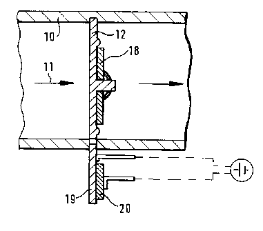
Figure 1 shows a valve with a heating arrangement,
Figure 2 shows a valve in a top plan view,
Figure 3 shows a duct for crankcase gases with integrated heating tube,
Figure 4 chows a valve embedded in a synthetic resin body,
Figure 5 chows a first variant of a heating tube,
Figure 6 .shows a second variant of a heating tube.
The sectional view presented in Figure 1 shows a simple plate valve which is
disposed in a
duct 10. The crankcase gases flow through this duct in the direction of the
arrow 11 into
the clean air section of an air filter. The valve is comprised of a copper
plate 12 which,
as shown in Figure 2, is provided with openings 13, 14, 1 S, 16 and 17. On the
copper
plate is a resilient valve plate 18. This plate is omitted in Figure 2 for a
clearer
illustration of t:he openings. The copper plate 12 is provided with a
projection 19. On this
projection 19 there is a cold conductor element 20. Receptacles 21 and 22 are
arranged on
the cold conductor element 20 and on the copper plate 12, respectively. A
voltage is
delivered through these receptacles. As soon as the temperature of the copper
plate, and
hence also the temperature of the cold conductor connected to the copper plate
falls below
a certain reference point, a heating current flows which heats the plate. This
has the
advantage that no additional regulating means are necessary.
Figure 3 shows an alternative embodiment. Here the crankcase gases pass
through a hose
23. The crankcase gases flow into the upper opening 24 and leave this hose
through the
bottom opening 25. In the center of the hose is a tube carrying cooling water.
This
cooling water tube 26 is connected to the cooling circuit of a vehicle or
motor and thus
warms this hose up to the temperature range of the cooling water. In this way
the freezing
or icing up of this line and of the following lines is reliably prevented. The
hose itself is
provided with two cylindrical connectors through which the tube can easily be
installed
and made sufficiently leakproof by appropriate compression.
SUBSTITUTE SHEET (RULE 26)

w CA 02226875 1998-O1-14
WO 97/03285 PCT/EP96/02033
4
In Figure 4 a valve is shown which is composed of a valve or copper plate 12
with a
resilient valve plate 18. The valve is disposed on a tube 10. The cold
conductor element
20, which is provided with prongs 21 and 22, is situated on the valve. The
prong contacts
are contained in a connector housing 27. The connector housing, the valve and
the tube
are enclosed together by a synthetic resin body in the joint area. In the area
29 the
synthetic resin body 28 surrounds the seam between tube 10 and the valve.
Furthermore,
the plastic body 28 forms a connector stub which can be connected to the
intake manifold
of an internal combustion engine. The connection is made, for example, through
a mirror
weld. For the optimum joining together of the parts, bores 30 can be provided
circumferentially on tube 10, the connector part 27 or the valve, through
which the
synthetic resin material flows during the injection molding and thus creates a
form-locking
connection.
Figure 5 shows the variant of a hose 23 through which the crankcase gases are
conveyed.
The crankcase gases flow in at the opening 24 and leave this hose through the
opening 25.
In the hose there is a tube 31 carrying cooling water, which has a fluid inlet
32 and a fluid
return 33. The tube is divided into two parts. The division can be produced by
a
separating wall 34 located in the tube. It is also possibile to make this tube
up of two
tubes, one inside the other coaxially. In the forward portion of the tube the
fluid is
returned. This forward portion is provided with a supporting body 35. The loss
of cross
section around the coolant tube can be offset by giving the hose 23 a larger
diameter.
Figure 6 shows an additional variant in which a tube carrying cooling water is
disposed in
a hose 23, and is comprised simply of a tube bent around 180°. The bend
is disposed in a
pocket 37 in hose 23, so that it does not diminish the cross section.
SUBSTITUTE SHEET (RULE 26)

Representative Drawing
A single figure which represents the drawing illustrating the invention.
Administrative Status

2024-08-01:As part of the Next Generation Patents (NGP) transition, the Canadian Patents Database (CPD) now contains a more detailed Event History, which replicates the Event Log of our new back-office solution.

Please note that "Inactive:" events refers to events no longer in use in our new back-office solution.

For a clearer understanding of the status of the application/patent presented on this page, the site Disclaimer , as well as the definitions for Patent , Event History , Maintenance Fee  and Payment History  should be consulted.

Event History

Description Date
Inactive: IPC deactivated 2019-01-19
Inactive: First IPC assigned 2018-03-05
Inactive: IPC removed 2018-03-05
Inactive: IPC assigned 2018-03-05
Inactive: Expired (new Act pat) 2016-05-11
Inactive: IPC expired 2016-01-01
Grant by Issuance 2007-01-09
Inactive: Cover page published 2007-01-08
Pre-grant 2006-10-26
Inactive: Final fee received 2006-10-26
Amendment After Allowance Requirements Determined Compliant 2006-08-07
Letter Sent 2006-08-07
Amendment After Allowance (AAA) Received 2006-07-10
Notice of Allowance is Issued 2006-05-18
Letter Sent 2006-05-18
Notice of Allowance is Issued 2006-05-18
Inactive: Approved for allowance (AFA) 2006-05-08
Amendment Received - Voluntary Amendment 2006-04-11
Inactive: IPC from MCD 2006-03-12
Inactive: S.30(2) Rules - Examiner requisition 2005-10-11
Letter Sent 2003-06-09
Request for Examination Received 2003-05-09
Request for Examination Requirements Determined Compliant 2003-05-09
All Requirements for Examination Determined Compliant 2003-05-09
Amendment Received - Voluntary Amendment 2003-05-09
Inactive: Single transfer 1998-05-08
Inactive: First IPC assigned 1998-04-24
Classification Modified 1998-04-24
Inactive: IPC assigned 1998-04-24
Inactive: IPC assigned 1998-04-21
Inactive: Courtesy letter - Evidence 1998-04-14
Inactive: Notice - National entry - No RFE 1998-04-07
Application Received - PCT 1998-04-06
Amendment Received - Voluntary Amendment 1998-01-14
Application Published (Open to Public Inspection) 1997-01-30

Abandonment History

There is no abandonment history.

Maintenance Fee

The last payment was received on 2006-05-01

Note : If the full payment has not been received on or before the date indicated, a further fee may be required which may be one of the following

  • the reinstatement fee;
  • the late payment fee; or
  • additional fee to reverse deemed expiry.

Patent fees are adjusted on the 1st of January every year. The amounts above are the current amounts if received by December 31 of the current year.
Please refer to the CIPO Patent Fees web page to see all current fee amounts.

Owners on Record

Note: Records showing the ownership history in alphabetical order.

Current Owners on Record
FILTERWERK MANN & HUMMEL GMBH
Past Owners on Record
HANS-WERNER HOLCH
HEINZ MUELLER
THOMAS BUTZ
Past Owners that do not appear in the "Owners on Record" listing will appear in other documentation within the application.
Documents

To view selected files, please enter reCAPTCHA code :


To view images, click a link in the Document Description column. To download the documents, select one or more checkboxes in the first column and then click the "Download Selected in PDF format (Zip Archive)" or the "Download Selected as Single PDF" button.

List of published and non-published patent-specific documents on the CPD .

If you have any difficulty accessing content, you can call the Client Service Centre at 1-866-997-1936 or send them an e-mail at CIPO Client Service Centre.


Document
Description 
Date
(yyyy-mm-dd) 
Number of pages   Size of Image (KB) 
Representative drawing 1998-04-28 1 5
Abstract 1998-01-13 1 50
Description 1998-01-13 4 164
Claims 1998-01-13 2 44
Drawings 1998-01-13 5 78
Abstract 1998-01-14 1 9
Description 1998-01-14 5 194
Claims 1998-01-14 2 49
Claims 2006-04-10 1 23
Description 2006-07-09 6 206
Abstract 2006-11-05 1 9
Representative drawing 2006-12-04 1 7
Reminder of maintenance fee due 1998-04-06 1 111
Notice of National Entry 1998-04-06 1 193
Courtesy - Certificate of registration (related document(s)) 1998-07-30 1 140
Reminder - Request for Examination 2003-01-13 1 112
Acknowledgement of Request for Examination 2003-06-08 1 173
Commissioner's Notice - Application Found Allowable 2006-05-17 1 161
International preliminary examination report 1998-01-13 17 640
Correspondence 1998-04-13 1 28
PCT 1998-03-11 7 210
Correspondence 2006-10-25 1 38