Note: Descriptions are shown in the official language in which they were submitted.
CA 02227167 1998-01-16
Internal Combustion Rotary Engine
Technical Field
The invention relates generally to internal combustion engines, and has
particular reference to a rotary engine, especially a rotary engine of the type set
forth in the preamble of the attached claim 1.
Back~round Art
One of the tendencies of improving the overall efficiency of traditional
volumetric displacement internal combustion engines has been the replacement of
the reciprocating pistons of such engines by rotary pistons capable of converting
the energy content of the expanding high pressure combustion gases into a directrotary movement of a driving shaft. The rotary piston engine known as the Wankelengine has been developed furthest in this field, but has not managed to supplant
the reciprocating engine due to problems with e.g., sealing materials. Other
attempts have been aiming at the development of rotary engines in which a rotor
is driven by at least one jet stream of expanding gases which exert a tangentialpressure on the circumference of the rotor whereby a part of the energy content of
the expanding gas is converted into a driving torque acting on said rotor.
Examples of engines of the kind concerned are turbines, especially gas turbines
that have found wide-spread application in certain well defined areas. Mainly from
literature, designs of internal combustion rotary engines have become known in
which a rotor is driven by a continuous series of impulses of expanding
combustion gases.
A known prior art device disclosed in US Patent 4,590,761 granted to
Zettner, comprises spaced combustion chambers with recesses therebetween
that are arranged around the outer circumference of a rotor. Each recess serves
as an expansion chamber for a jet of gas produced by combustion in an
associated combustion chamber. A stator has at its inner circumference,
retractable reaction members which are movable into the recesses to be acted on
by the gas jet so as to create forces acting in opposite sense on the rotor and
stator and thus cause the rotor to rotate. This known device seems to be too
elaborate since it comprises a large number of cam-controlled movable
component parts, and since fuel combustion is performed in open chambers of
throttled discharge openings only, the thermal efficiency may also be not
sufficiently high for the engine to be viable of practical application.
CA 02227167 1998-01-16
Another device of the type concerned is disclosed in the published German
patent specification DE 1 601 577 A2. The device disclosed herein comprises two
equidistantly spaced combustion chambers arranged in a stator along its
circumference. Combustion gases generated in these combustion chambers are
discharged, at pre-determined intervals into a generally snake-shaped expansion
duct which is confined by curved wall partitions of chambers certain parts of which
being arranged in both, a rotor of the engine and in said stator. When the engine
is supposed to be in operation, said chambers become connected with each other
in sequence so that multiple and subsequent expansions of the combustion
gaseswould exert alternating active and reactive tangential driving impulses onto
the rotor. The expanded combustion gases are finally vented via a duct through
the stator in the ambient atmosphere. Considerations given to the disclosed
device allow for the conclusion that the device would hardly be capable of
practical operation at ieast in the sense of supplying a driving torque that could be
utilised at viable efficiency. The generally snake-shaped expansion duct seems to
be too long and too voluminous. In such an expansion duct a permanent counter
pressure of substantially constant level may be generated. During the relativelylong periods between the successive combustion impulses in the chambers the
combustion gases present in said duct may come to a quasi-stagnation. The rate
of flow of the gas through said expansion duct is expected to be substantially low
because said too long intervals and the relatively large volume of the expansionduct allow for a low velocity, slow release of the expanded combustion gases in
the ambient atmosphere. Between the actively and/or reactively driven wall
partitions of the rotor chambers long wall sections are present that are, in view of
torque generation, at least entirely inactive if not of retroactive effect.
Another example for such an engine is disclosed in the German patent
publication DE 1 476 913 A1. The device disclosed herein is, in principle, a multi-
stage turbine comprising a rotor provided, in spaced arrangement, with spaced
chambers having tangential openings along the circumference of the rotor. When
in operation, impulses of a high pressure gas jet are introduced tangentially into
said chambers. The impulses exert active and reactive driving forces onto the
rotor both upon their entry and also later, during their multi-stage expansion from
the chambers. The rotor of the known device is designed and shaped as a hollow
cylindrical body having radially directed spokes, and the chambers are arranged in
an outer circumferential ring part of the cylindrical body. As an alternative, the
same publication discloses the possibility of generating the high pressure gas
impulses, at least within the first expansion stage of the turbine, by arranging and
operating internal combustion chambers in the rotor. Following the first stage of
~ c~
CA 02227167 1998-01-16
their expansion, the combustion gases are introduced, via suitable but reiatively
long conduits, into subsequent stages of the turbine for repeated expansions.
Combustion of fuel introduced in the combustion chambers would be performed at
constant volume, and the expanding gases would exert, at least during their first
stage of expansion, impulses of reactive driving torque on the circumference of
the rotor. Due to the relatively long paths of flow for the expanding gases between
the subsequent expansion stages and to multiple bends arranged therein, this
hybrid solution seems to be hardly efficient enough and thus, capable of replacing
the well known reciprocating engines.
The published German patent application DE 3826533 A1 discloses an
internal combustion rotary engine having a rotor provided with a plurality of
recesses adapted to receive a gas jet of expanding high pressure combustion
gases discharged ftom a combustion chamber arranged stationary and in sealed
relationship to a pheripheral section of the rotor. When in operation, i.e. the rotor
of the engine rotating relative to the combustion chamber, the recesses of the
rotor are facing, temporarily and in sequence, the discharge outlet of the
combustion chamber. The rotor is kept in continuous rotational motion by the
kinetic energy of the jets of the expanding high pressure combustion gases beingtransferred to the rotor by and during their passage through, and further
expansion in the recesses of the rotor. The rotor of the internal combustion rotary
engine disclosed in DE 3826533 A1 is designed and shaped as a substantially
solid body of rotation, and apart from a brief indication of the heat content of the
expanded combustion gases being further utilised by a heat exchanger, no
information is disclosed on how the spent combustion gases are released after
their expansion.
It is accordingly one object of the present invention to provide an internal
combustion rotary engine, especially an engine operating on the principle of a
rotary engine driven by a continuous series of tangential impulses exerted onto a
rotor by expanding combustion gases of high energy content, the basic design of
which would allow for the provision of engines different in size and thus, in
performance by using and aligning by simple assembling, different numbers of
pre-manufactured, identical component parts. More particularly, the present
invention seeks to provide an internal combustion rotary engine that operates with
a minimum of losses of energy at high thermal and mechanical efficiency. A
further and related object of the present invention is to provide an engine of
hitherto not experienced low fuel consumption, the engine being capable of
operating with different types of fuel, particularly of liquefied or gaseous hydrogen,
in a problem-free manner. Still another object of the invention is to provide a
~ S,~.
CA 02227167 1998-01-16
- 4 -
rotary engine that could replace with considerable advantages, the traditional
reciprocating internal combustion engines in every field of application. Yet another
object of the invention is to provide a method for operating the engine according
to the invention in a manner friendly to environment, by producing, if at all, a very
low proportion of noxious constituents in its exhaust gases.
It has been recognised that the above and complex objectives can only be
realised by providing an engine of the rotary type in which principles and physical
effects known, at least in part, such as avoiding reciprocating component parts;using and utilising a rotor of high product of inertia for storing, at least for certain
periods of operation, kinetic energy; burning a completely combustible fuel mixture
in heat insulated spaces so that adiabatic combustion is performed, allowing andutilising fuel combustion by detonation whereby higher combustion rates and
pressures can be achieved, are asserted simultaneously.
Disclosure of the Invention
According to the present invention there is provided an internal combustion
rotary engine comprising a circular inner element mounted to be rotatable thereby
to function as a rotor of the engine and a concentric, substantially annular outer
element mounted to be stationary thereby to function as a stator of the engine.
The rotor and the stator are disposed so that the inner circumference of the stator,
at least in certain pre-determined circumferential sectors thereof, sealingly
surrounds the rotor. The rotor and l:he stator are mounted for relative rotationabout the axis of concentricity thereof. The stator is provided with at least two
combustion chambers equidistantly spaced around said circumference, each of
the combustion chambers have a discharge outlet opening tangentially into said
circumference towards the rotor. Each of the combustion chambers further has at
least one fuel inlet through which oxygen or air and fuel, in pre-determined
amounts such as to form a combustible mixture, can be injected into the
combustion chamber at pre-determined intervals. The combustion chamber
further comprises means for initiating or enhancing the ignition of the combustible
mixture injected into said combustion chamber. The rotor is designed so as to
form a generally ring-shaped body of rotation having an outer ring body connected
to a central shaft by a plurality of spokes in a rigid, torque transmitting manner.
Said central shaft protrudes, at least at one of its end portions, from the ring body,
and is mounted to serve as the main shaft of the engine. The ring body is
provided with a plurality of recesses adapted to receive a gas jet of expanding
high pressure combustion gases discharged from the combustion chambers
CA 02227167 1998-01-16
through their discharge outlets when the recesses are, temporally and
sequentially facing said discharge outlets during the relative rotational movement
of the rotor in relation to the stator. According to one of the novel characteristic
features of the invention the rotor consists of at least two rotor segments thatcomprise a ring segment having a thoroughfare inside through which a continuous
stream of gas such as ambient air passes through the rotor in one axial direction
during operation. The recesses in the rotor segments are designed and shaped so
as to form at least one group of thoroughfare expansion channels capable of
continuously rotating the rotor by converting the energy content of the combustion
gases into driving torque exerted in form of impulses acting tangentially on thering segments of the rotor. Another novel feature of the invention lies in that each
of the expansion channels provide a direct connection for the combustion gases
from said discharge outlets of the combustion chambers towards the inside of therotor segments at intervals when inlets of the expansion channels along the outer
circumferences of the rotor segments are facing said discharge outlets along theinner circumference of the stator.
Brief Description of Drawin~s
Other features and advantages of the invention will be apparent from the following
description of preferred embodiments, by way of example only, with reference to
the accompanying drawings, in which:
Fig. 1 is a perspective view of a rotary engine embodying the
invention and consisting of four identical segments in which
each stator segment comprises two combustion chambers,
Fig. 2. is a perspective view of one of the segments of the rotary engine
shown in Fig. 1,
Fig. 3 is a partial top view of the segment shown in Fig. 2 wherein
a segment lid of the stator segment and a cover disk of
the rotor segment are removed to expose one of the combustion
chambers and one group of the expansion channels of the engine
segment,
Fig. 4 shows a perspective view of the segment body of the stator
segment of the engine revealing also arcuate seal members
together with their locations and seatings,
Fig. ~ depicts a partial elevation of one of the rotor segments of
,~ S~
CA 02227167 1998-01-16
W O 97/04226 PCTAHU~6~ 3
-- 6--
the engine,
Fig. 6 is an elevated perspective view of a ring segment of the
rotor segment shown in Fig. 5,
Fig. 7 is an elevated parlial per;,pecli~/e view of a portion of one
segment of the rotary engine with the segment lid and the
cover disk removed again to reveal details of the construction
of the combustion chamber and the arcuate seal member
~ssoci led therewith,
Fig. 8 is a view similar to Fig. 6 but showing the ring segment of
a modified embodiment of the rotor segment of the rotary
engine; and
Fig. 9 the perspective elevation of an altemative embodiment
of the rotor of a four-segment rotary engine emboJ~ing the
invention.
Best Mode for Carrvinq Out the Invention
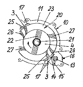
In the preferred embodiments shown, by way of example only, in Figs. 1 to
9 of the accompanying drawing, the internal combustion rotary engine embodying
the invention has a stator 1 and a rotor 2 co"si~ ,y respectively, of four identically
shaped stator segments 10 and four identically shaped rotor segments 20. The
segments are aligned co-axially along a main shaff 21. Each of the stator
segments 1 comprises a segment body 11 a side face of which is sealingly
covered by a segment lid 12. Each rotor segment 20 consists of a ring segment
23 and a cover disk 24. The cover dislc 24 is in diameter equal with and sealingly
mounted onto one side face of the ring segment 23. The rotor 2 is designed so
that it forms a generally ring-shaped body of rotaliGi, having a relatively highproduct of inertia. To ensure this, the ring body consisti,ly of four ring segments
23 and four cover discs 24 is connected to the main shaft 21 by a plurality of
spokes 22 in a rigid, torque Ir~nslnitting manner. The main shaff protrudes at both
of its end portions from the rotor 2 and serves as the main shaft 21 of the engine.
In accordance with one of the important novel characteristic features of the
invention the rotor 2 has a thoroughfare inside 4 through which a continuous
stream of ambient air can pass through the rotor 2 in axial direction during
CA 02227167 1998-01-16
W O 97/04226 PCTAHU96/00039
--7 --
operation. Fig. 2 shows the perspec~ive view of one engine segment that would
be in itself alone, c~p~hle of working in certain low power ranges. Since
throughout the dra~lv;..gs idetllical cc"."~ol.ent parts of the engine have beenassiy. .ed the same ~e:f~re:"ce numerals, there seems to be no need for a repeated
detailed ~lesc,i~.lion of the engine segment .~ t-- in Fig. 2. As shown in Figs. 3
and 4 each segment body 11 is provided with two combustion chambers 13
sp~Gerl e~ stantly around and radially from the inner circumference of the
stator 1. Each combustion chamber 13 has a discharge outlet 14 and a fuel inlet
15. .esides fuel such as e.g. Iiquid hydrogen also compressed air or oxygen and
if desired water can be injected through the fuel inlet 15 in controlled amountsand at pre-determined intervals into the combustion chamber 13. As further
shown in Figs. 3 4 and 7 each segment body 1 1 of the stator further col I ".rises
se~li..ys 17 for housing an arcuate seal member 3 and a bore for a spark plug 16for each combustion chamber 13 while the ring seylllellls 23 of each rotor
segment 20 comprises for each combustion chamber 13 a group of three
successive expansion channels 25 26 and 27 as it is apparent from the drawing
Figs. 3 and 5 to 7. In ordler to ensure adequate provisions for adiabatic
combustion the engine has heat insulated preferably heat resistant ceramic-linedcombustion chambers 13 discharge outlets 14 and expansion channels 25 26
27 and the rotor segments 20 of the rotor 2 are along their outer circumference
similarly heat insulated preferably heat resistant ceramic-lined component partsof the engine. The inner circumference of the stator segments 10 is in
circumferential sectors where the discharge outlets 14 of the combustion
chambers 13 open tangentially into said circumference towards the rotor 2
provided with sealing means for a sealed but still rotatable engagement between
the stator segment 10 and the rotor 2 in said circumferential sectors thereof. As
sealing means arcuate seal members 3 are provided for that are inserted against
the action of pre-stressed spring means (not shown in the drawing figures) in
suitable seatings 17 recessed into the inner circu.."t:r~"ce of the stator segments
10. Each arcuate seal member 3 has a thoroughfare opening 30 whereby a free
flow of the high pressure combustion gases from the discharge outlets 14 of the
combustion chambers 13 towards the rotor 2 and into the expansion channels 25
26 and 27 is "~wod for at intervals when the inlets of said expansion channels
25 26 and 27 along the outer circ~.",fert:nce of the corresponding rotor segment
CA 02227167 1998-01-16
W O 97/04Z26 PCTnHU96,'~C~3
-- 8--
20 are facing said discharge outlets 14 along the inner circumference of the stator
1. The arcuate seal mel"ber~i 3 are interchangeable wear parts made of a suitable
coal Illdtelial. Each arcuate seal member 3 is provided with two seal ribs 31, 32 of
circular segment-shaped cross section. The seal ribs 31, 32 protrude along
parallel lines both sides of the opening 30 from the arcuate inner circumference of
the seal member 3, and they are in matching engagement with and thus, form
gas-proof seals against annular sliding and sealing surfaces 28, 29 of the rotor 2
along the ,~ fer;ably cerc.l),ic-lined outer circumr~re,.ce of the col,esponding rotor
segment 20. Such a design of the peripheral sealing means allows for the engine
to be lubricated simply by water. Each combustion chamber 13 of the engine
shown in the drawing has a volume of around 8 cm3 at a depth of 1 cm. The
discharge outlets have a nominal cross section of 0.5 x 1 cm, and they are shaped
as Laval no~71es known per se. The fuel inlets are a,lanyad at a loc~tion so that
they provide for a rapid mixing and a complete combustion of the fuel after
injection. The timed feeding of high pressure air or oxygen, of fuel (preferablyhydrogen) and optionally of water into the combustion chambers 13 through the
fuel inlets 15 is performed and controlled preferably by means of plain slide valves
known again, per se. The nominal radius of the common circumference of rotation
between the stator 1 and the rotor 2 is 12 cm. The stator segments 10 and the
rotor segments 20 are of 4 cm thickness, each. The segment body 11 has a
thickness of 2.5 cm, and the thickness of the segment lid 12 amounts to 1.5 cm.
Similarly, the ring segment 23 has a thickness of 2.5 cm and the cover disk 24 is
1.5 cm in thickness. The radius of the inside 4 in the rotor 2 is 8 cm. As it isapparent from the drawing, the stator segments 10 of the stator 1 can be very
easily aligned and they are held together by threaded rods (not shown) arranged
around the outer periphery of the stator 1 in axial direction. With the dimensions
indicated further above, the largest 4diameter" of the rotor segments (measured
along a line through the central points of the two opposite combustion chambers
13) amounts to 43.2 cm while the outer "diameter" of the preferably light metal
segment body 11 and segment lid 12 is 32 cm. Each engine segment weighs
(without the main shaft 21) around 8.7 to 8.8 kgs so that the total weight of a four
segment engine comprising sixteen combustion chambers 13 in total, amounts
(without a main shaft 21 of the lengths of 30 cm again) to app. 35 kgs.
.
CA 02227167 1998-01-16
W O 97/04226 PCTnHU96/00039
_ 9 _
Figs. 3 and 5 to 7 of the ~rawing show clearly that the rotor segments 20 of
the rotor 2 comprise two groups of expansion channels 25, 26 and 27. The inlets
of the ex~c~al)sioll channels 25, 26 and 27 of each group are a"dllyed in pre-
dete, l l ,il led sp~ce~ l eldliGl ls to each other along the outer circul l ,r~ e nce of the
rotor segment 20. The ex~,ausioll Challllel~S 25, 26, 27 are channels of narrowing
cross-section towards the inside 4 of the rotor 2 and they are recesserl into one
side face of the ring segment 23. The ex~dllsioll channels 25, 26, 27 have, whenviewed in the direction of rutal,~l), forward and rearward confining wall sections,
and both their forward and rearward wall sections are shaped, starting from their
inlets along the outer circulllrerellce of the rotor 2, as turbine blade-like arcuate
wall sections. In other preferred embodiments of the rotary engine en,bodying the
invention the expansion channels may be .lirrerenl. In one alternative design
shown (without main shaft 21 ~nd sp~kes 22) in Fig. 8 of the attached drawing, aring segment 23' has a side face provided with an axially protruding annular rim at
its outer circumference, and a cover disk 24 that is again, in diameter equal with
and mounted onto said rimmed side face of the ring segment 23'. In this
alternative embodiment, each group of channels consists of two expansion
channels 25', 26' that are designed and shaped as thoroughfare channels
arranged in the ring segment 23' in a manner that they start, when viewed in thedirection of rotation, in tangentially forward direction from their inlets along the
outer circumference of the ring segment 23', curve rearwardly and in sideward
dileclioll, and open into said rimmed side face of the ring segment 23'. From here,
the expansion channels 25' and 26' are in direct connection with the inside 4 ofthe rotor 2 since the rimmed side face of the ring segment 23' provides for an
annular hollow space between the rimless inner circular portion of said side face
and the cover disk 24 that is open, in radial directions, towards the inside 4 of the
rotor 2.
Figs. 4 and 5 of the drawing show the preferred design and construction of
the arcuate seal members 3. It is apparent from the drawing figures that their
seatings 17 are recessecl in the inner circumferences of both the segment body
11 and the segment lid 12 of the stator segment 10. The seatings 17 are of a
radial depth so that the arcuate seal members 3 can be withdrawn radially against
the action of the pre-stressed spring means (not shown but already mentioned
further above) when and during the roltor 2 is inserted into the stator 1, or removed
CA 02227l67 l998-0l-l6
W O 97/04226 PCTnHU9C~ D3
-10 -
thelerlulll in axial direction. The drawing figures show further that one of the two
seal ribs 31,32 of circular segment-shaped cross section protruding both sides of
the opening 30 along par "el lines from the arcuate inner circu",rerence of the
arcuate seal member 3, namely the seal rib 32 is enyayes with and thus, providesfor a gas-tight seal against an annular sliding and sealing surface 29 along the,~referably ceramic-lined outer circumference of the ring segment 23 of the rotor
segment 20. In the same manner, the seal rib 31 corresponds and provides for a
gas-tight seal with the annular sealing surface 28 of the preferal)ly cerdmi~-lined
cover disc 24 of the rotor segment 20. The openings 30 of the arcuate seal
members 3 are shaped wide enough so that the expanding combustion gases of
the temperature between 1500 and 1600 ~K (even if addilional water is injected
into the combustion cl,~l"bers 13 after each complete combustion but before
expansion) will not CGI ,tact the arcuate seal members 3 directly upon their
expansions through the discharge outlets 14. On the other hand, the peripheral
lengths of the arcuate seal mernbers 3 ensures that each seal member 3 is
capable of simultaneously and sealingly closing the inlets of both expansion
channels 25 and 26 of the same group of channels when they are just in facing
relation to said seal member 3 during operation.
From the point of view of operation that will be described in detail further
below, an important characteristic feature of the invention lies in that the rotor 2 of
the engine is open at its both end portions and thus, has a thoroughfare inside 4
through which a continuous stream of ambient air can pass through the rotor 2 inaxial direction, during operation. This is well enhanced by the provision of thetorque transmitting connection between the annular ring segments 23 or 23' and
the main shaft 21 of the rotor 2 via spokes 22. AccGrdi. ,9 to a further feature of the
invention at least some spokes 22 of the rotor 2 are designed and shaped so as to
serve, in operation, as axial fan blades for generating and maintaining a space of
somewhat (preferably by 5 to 20 kPa) lower pressure in, and an axial flow of
ambient air for scavenging the rests of expanded combustion gases from the
expansion channels 25,26,27; 25',26' and cooling the rotor 2, through the inside4. Said inside 4 can also be equipped, at one of its end portions, with an inletchamber (not shown) having a suction filter, and with another chamber at its other
end portion for temporary collecting the expanded combustion gases prior their
release in the ambient atmosphere.
CA 02227167 1998-01-16
W O 97/04226 PCT~HU96/00039
- 11 -
For its effective, normal operation, the rotary engine accGrdi"y to the
present invention as shown in the attached drawings and desc,iL,ed above, will
have to be Associ~te~ with well known auxiliary devices such as a starter whereby
the main shaft 21 is brought in .otaliu,- b~fore and through initial iylliliOIl; a break
which can pref6rdbly be a disc break working also in ~soci~tioil with the main
shaft 21; a ~r~rt:rdbly ele.;tru~,ic injecting device capable of co,.ll~ injecting
oxygen (or high pressure air), ~uel, preferably hydrogen and as a prt:fer,ed option,
also pre-determined amounts of water, in a controlled manner into the engine's
combustion chambers 13; yet another, preferably electronic device for effecting
the conlrùllEI ignition of the injected fuel mixture in the combustion chambers 13
by spark plugs 16; and a suitable gear box, preferably of the electronically
COnll~.J113d automatic kind known, in various embodiments thereof in the field of
aulu,,,c,li~/e vehicles. Parameters and fu"ctiol,s of the engine, together with those
of its auxiliary devices mentioned above, are in most ,~re:fer, t:~l, up to dateembodiments of the invention, integrally controlled by an electronic board
computer.
In the following, best and alternative modes of operating the preferred
embodiment of the rotary engine, together with certain characteristic data thereof
will be described in a more detailed manner.
In accordance with the general characteristic features of one best mode
method accordi"g to the invention, the engine is operated by injecting
intermittently, in amounts depending on the prevailing actual engine performancerequirements and at pre-dele""i"ed sequential intervals controlled in accordancewith the number of groups of ex~a~siGn channels 25, 26, 27 or 25', 26' in, theirsp~ced relationship along the circumference, and the actual speed of revolution of
the rotor 2, oxygen or air and fuel that would form a fuel mixture c~p~ of
complete combustion in the combustion chambers 13; causing the fuel mixture, by
controlled ignition or spontaneously to burning, preferably by detonation, at
constant volume by keeping said combustion chambers 13 gas-tightly sealed until
the peak combustion pressure therein is reached; expanding the high pressure
combustion gases, preferably in three or at least two expansion steps in
sequence, in the form of impulses of gas jets directed tangentially, via the
discharge outlets 14 of the combustion chambers 13 into the expansion channels
25, 26, 27 or 25', 26' by bringing, through the rotation of the rotor 2 relative to the
CA 02227167 1998-01-16
W O 97/04226 PCTnHU9~/~G~ - 12-
stator 1, the circumferential inlet openings of the expansion channels 25, 26, 27 or
25', 26' in t~lllpGIary facing relaliGI~ship with the discharge outlets 14 of the
combustion chambers 13; and by removing the expanded combustion gases from
the ex~ ,.sio" channels 25, 26, 27 or 25', 26' through the hollow inside 4 of lower
pressure of the rotor 2. During operation, after the combustion preferdbly by
detc,l)~licJi- has been concl~ded in a combustion cl,ar,lber 13, and an (in the
direction of l otaliG") first ex~c,al ~SiGU channel 25 arrives at its circu"~fel enlial
position facing the discharge outlet 14 of the combustion chamber 13 concerlled,the combustion gases of still maximum pressure and temperature are discharged,
in the form of a tangential hot gas jet in the first expansion channel 25, and they
exert, while expanding, a considerable impulse of pressure and thus a pushing
impulse agail,~l the arcuate, forward wall portion of said channel. The arcuate
forward wall pGI Lion of the ex~usioil channel 25 (similarly to those of the
succee~ g ex,~.al,siol, channels 26 and 27) is shaped such that the pallicle., of
gas that have been trying to maintain their direction of motion are forced to
continuously alter their path of movement, nearly until an angle of turn of slightly
less than 180~ is performed while they move towards the inside 4 of the rotor 2.During their travel, the gas particles continuously transfer and thus, gradually loos
their energy content while they slow down, simultaneously. Since, however, the
gas particles are acting against wall portions rotati"g at constant angular velocity
but of gradually smaller radius and thus, of diminishing velocity of advance, a long
lasting, continuous energy l,an~;rer is performed along their entire path of travel
because the wall pollions transforming pressure into force and thus, into driving
torque would not "escape" from the impacts of particles of the expanding gas. The
peripheral length of the arcuate seal members 3 and the peripheral distance
between the inlets of the successive expansion channels 25 and 26 have been
selected so that the arcuate seal member 3 will simultaneously cover the
peripheral inlets of both expansion channels 25 and 26 whereby the (remaining)
pressure in the combustion chamber 13 is maintained until the inlet of the
expansion channel 26 arrives in its position facing the discharge outlet 14. In this
position, a second gas jet impulse generated by and carrying a "second stage"
energy content of the remaining combustion gases is discharged into the
expansion channel 26, and it will be utilised therein, for driving torque generation
in the same manner as described further above. In rotor segments 20 having a
CA 02227l67 l998-0l-l6
W O 97/04226 PCTnnU96/00039
-13-
ring segment 23 with three successive expansion channels 25, 26 and 27, energy
lldll~rt:r is performed even in the last expansion channel 27 the main task of which
is to ensure that even low pressure rests of the cornh~stion gases are removed
from the combustion chamber 13. This is further ~nl)anced by the lower pressure
and the axial flow of am'iel~l air maintained, for scavenging the rests of expanded
combustion gases from the exl a"siorl channels 25, 26, 27 or 25', 26', and cooling
the rotor 2, in and through the inside 4 of the latter.
In order to achieve its rr~ain goals and best performance, the rotary engine
embodying the invention is operatecl by using liquefied hydrogen with oxygen
added thereto in amounts capable of fully oxidising the hydrogen injected into the
combustion chambers 13. For starting, hrst the rotor 2 is set in rol~lio"al motion
by using any known starter device as r~f6~r.ed to further above. The minimum
speed of revolution required for starting does not need to be higher than 60 to 80
r.p.m. which is in range of that of lhe l-ddilic".al re~ ,r,c~li"y engines. Since
however, the rotor 2 of the rotary engine according to the invention is freely
rotatable (with no resistance that would result from compression), starting speeds
in the order of 600 r.p.m. can be easily realised by using a starter of conventional
performance. Having reached the desired speed of revolution, the engine is
started by injecting oxygen, followed by hydrogen through the fuel inlets 15 in the
combustion chambers 13 and by initiating combustion of the fuel mixture by
means of the spark plugs 1 G. All these phases of operation are controlled
electronically by a suitable board computer. In this starting phase of operationcombustion will not be performed under adiabatic CGI .dilions as long as the engine
is heated up to working temperature. Having arrived at this temperature, it is no
longer necessary for the spark plugs 16 to be kept in operation since the high
temperature of the insulated, ceramic-lined combustion chamber walls 13 alone
c~uses the fuel mixture to spontaneous combustion by detonation. The optimum
speed of revolution of the main shaft 21 may be in the order of 4000 r.p.m. In
certain helds of application however, higher values reaching even 6000 r.p.m.,
and also much slower speed values are possible. The speed of revolution of the
main shaft 21 is maintained at its optimum value by the board computer. Both,
overspeed and much to low speed values of rotation caused by varying load
cGn.lilions and other factors are corrected automatically. For cutting off the
engine's operation, i.e. for stopping the rotating motion of the main shaft 21 and
CA 02227l67 l998-0l-l6
W O 97/04226 PCTnHU96~'~C-39
-14 -
for adding cGnllullcd braking effect to the engine brake function in non-load and
among others, in possi~l~ emergency modes of operation if required, the use of at
least one disc brake device, acting on the main shaft 21, is recommended. An
ultimate requirement of ~perdlion is that combustion of the fuel mixture is
performed at const~ilt volume with the combustion chamber:, being gas-tightly
sealed throughout the entire, complete comh~ ~stion. To meet with this
requirement, hesides providing a suitable shape and maintaining the gas-tight
sealing effect of the arcuate seal members 3, the fuel i,.,e tion (and ignition) have
to be controlled in a manner that the combustion by detol~liGn in a closed spacewhich, in contrast to traditional reciprocating engines, is highly desirable with the
rotary engine according to the present invention, is completely concluded in thecombustion chambers 13 by the time the inlet of the first expansion channel 25
reaches its phase of ~otdlion facing the discharge outlet 14 of the respective
combustion chamber 13. Fulfilling the above requirement results in that the
expansion of the combustion gases and thus, the transfer of energy will start
always at times and intervals where maximum pressure prevails. With one of the
preferred embodiments of the engine as shown and described above, the
combustion gases are allowed to expand from each combustion charnber 13 in
three successive steps (or pressure stages). The first step of their expansion
starts with the inlets of the first expansion channels 25 reaching at and facing the
discharge outlet 14 of a combustion chamber 13 in which combustion gas, in fact
pure vapour of water, has been generated by completely burning a suitable dose
of a mixture of hydrogen and oxygen by reaching peak temperatures in the range
of 2500 to 2600 ~K, and a peak pressure of between 8 and 16 MPa. This first stepof expansion is followed by a second one through the expansion channel(s) 26,
and a third one through channels 27 (if any), resulting in full conversion of the
energy content into driving torque, and in the entire amount of expanded
combustion gas being removed from the respective combustion chambers 13 that
are ready now to receive a successive fuel charge by controlled injection. Each of
the expansion channels 25, 26, 27 has an effective wall portion of about 5 cm2 on
which pressure impulses are exerted upon each expansion. The average value of
the radii of pressure impacts amounts to 10 cm which is equivalent to an averagediameter and thus, to a torque generating arm of couple of 20 cm. Average
pressure values of the successive expansion stages are estimated to be in ranges
=
CA 02227167 1998-01-16
W O 97/04226 PCTAHU96~ 9
of 11 to 9 MPa, 8 to 5 MPa and 4 to 0.1 MPa, respectively. Practical realisation of
the higher values is highly probable since the initial high pressure of the gas
e,nely;~ly from the combustion chamber always acts at wall the portions of
"~xi",um radius. The main shaft 21 rotates at 4000 r.p.m. at maximum
l~e,Ft,l,l~a,lce of the engine. Since peak temperatures Iying between 2500 and
2600 ~K when the engine is operated by hydrogen would result in an extraordinaryhigh Ih~rl "al load even for heat insulating linings known from up-to-date
techniques, according to one of the provisions of the present invention, pure water
is injected in the combustion chambers 13 soon after combustion is concluded butbefore expansion. By doing so, the c0mbustion gases cool down to a temperature
between 1500 and 1600 ~K, while their pressure will also decrease accordingly.
Since however, by the a~l~lilio"al injection of water the amount of gas, i.e. vapour
contained in the cl,amLer is increased s~hst~ntially, the energy co"tel,l of thecl ,c-, "ber seems to rt:" ,ai, l practic~lly unchanged. Injecting water into the
combustion chamber can be applied, with good results, even if the engine is
operated by using fuel other than hydrogen. e.g. petrol, diesel, LP gas etc. Thecontrolled injection of water can be performed either by using the fuel inlets 15 of
the combustion chambers for this purpose, or through separate, additional inletsserving to water injection only.
In the preferred e~"bo.li")ent of the invention where each engine segment
comprises two combustion chambers 13 and two groups of expansion channels
having three expansion channels 25,26 and 27 each, four combustions per
segment, and in accordance herewith, four times three i.e. twelve expansion
stages per segment are performed during each full revolution of the main shaft 21.
When in full operation, in the four segment engine shown in Fig 1. of the drawings
the rotor 2 is driven by forty-eight expansion impulses per revolution. By using the
above mentioned, partly esti",~led data, the product of inertia of the rotor, the
driving torque and the estimated output of the main shaft 21 can be calculated
with substantial ease. Estimations in this direction have shown that the fuel
consumption of the engine accordi.,y to the present invention would be around
one sixth to one eighth of that of an average traditional reciprocating engine of the
same power output. Thank to this and other features such as burning fuel by
detonation being not only allowed but desirable, the use of so called hydrid fuel
tanks, or the safe storage of hydrogen in steel flasks both, in liquid form at
CA 02227l67 l998-0l-l6
W O 97/04226 PCTAHU96/00039
-16 -
al-l-ospheric pressure, or in its cor.pr~ssed gaseous state under a pressure of 25
bar would become entirely safe and appli~ even for and in ordinary motor
cars.
For ensuring a s~ t~.lially uniform, even distribution of the driving torques
exerted by the expansion imp~lces on the rotor 2, embodiments of the latter as
shown in Fig. 9 of the attached drawing seem to be especially advant~geolls. In
the e~.bo.li..,ent of Fig. 9 the idenlically shaped rotor segments 20 are aligned co-
axially along the main shaff 21 in a manner so that the groups of expansion
channels 25, 26 and 27 of each rotor segment 20 are arranged in equidistantly
phase-shifted relation to those of the jukla,l osed rotor segments 20 around themain shaft 21.
Full operdlio n of the engine means that the entire output power capacity of
the engine is needed and thus, all con-h!~stion cl,amber~ 13 are working at full~e, ~u" "ance. Such a full load mode of operation is rarely needed. More
charact~ristic modes are partial load and no-load modes of operation. There are a
number of possihi~ities for varying the output power of the engine. Some of these
possibilities can also be applied in combination. The simplest way of power control
would be the altering of the amounts of fuel injected in the combustion chambers.
The engine according to the present invention however, offers a more
advantageous, hitherto not exercised possibility for output power control by
suspending, especially in partial load and no-load run modes of operation, the
injecting of fuel and optionally, of air or oxygen into at least some of the
combustion chambers 13. Cutting off the chamber's work may be performed
individually, in certain groups, segment-wise, or even in more segments of the
engine. The rotor 2 having a relatively high product of inertia, is capable of storing
a considerable amount of kinetic energy. As a result of this, in certain, especially
no-load modes of operation where only frictional and possibly other losses need to
be covered, in a four segment engine as shown in the drawing and described
above, operating only one single segment may be sufficient. In order to maintain a
substantially equal distribution of thermal load and wear over the combustion
chambers 13 of the engine, sequentially conlr~llcd switch-overs between the
working and temporary suspended combustion chambers 13, preferably by
segments, can be performed with substantial advantage. As another provision
aiming at savings in energy consu"~lion, the speed of rotation of the rotor 2 is
CA 02227l67 l998-0l-l6
W O 97/04ZZ6 PCT~HU96/00039
-17 -
maintained between values of e.g. 3000 and 4000 r.p.m. even in no-load modes
of operation. When said speed reaches or approaches the lower limit value, the
board computer puts at least individual combustion chambers into operation. In
engine break modes of operation again, the brakil-y energy is used for speeding
up the rotor, and for avoiding an overspeed, either the disc brake mentioned
already further above is activated, or an ~d~ litiG,.al, fifth engine segment mounted
for and operated in o~posile sense of r~talicln may be applied.
Reference has already been made to the possi~ ;ly of operating the engine
according to the present invention by using fuel other than hydrogen. In fact, all
known kinds of fuel sllitAl-le for combustion are ~rFlic~hle for effective operation.
Through the inlet openings 15 e.g. complessed air and ordinary petrol can be
i..jected in a conl.-~ll d manner, in the combustion chambers 13. For pe,ru....i..y
the i,-jection, devices should be used that would be suitable for temporary
suspending the i--je~ n of at least the fuel co,.1pol-ent of the fuel mixture inindividual combustion chambers 13 or in certain groups thereof. As a further
auxiliary device, the engine needs an air compressor car~hl- of compressing 5 to6 of all,-ospheric air to a pressure between 2 to 6 MPa in continuous mode of
operation. The compressor has to be associated with a pressure vessel of
sufficient volume capable of storing an amount of high pressure air that would bneeded for re-starting the engine. The air consumption of the engine in full load
operation at 4000 r.p.m. is estimated to 3.2 to 3.8 m3 of all.lospheric air with an air
ratio amounting to values between 0.9 and 1.1. This is much less than the air
consumption of a 2000 to 2500 cm3 lr~Jiliollal engine of app. the same output
power. For the controlled air and fuel injection also here, the use of solenoid
controlled plain slide valves is recommended. The air ratio may p r~ft:rably be
co,-l,olled by altering the amount of the air charge injected, and before concluding
the expansion in its preferably third stage, the respective expansion channels
should be flushed by small amounts of fresh air injected therell ,rough.
Certain losses are inevitably associated even with the rotary engine
according to the invention. Friction losses occur in the preferably slide bearings of
the main shaft 21. Further friction losses arise between the arcuate seal members
3 and the circumference of the rotor 2. A possibility of reducing the latter lies in the
provision of retracting arcuate seal members 3 ~ssoc~ated with temporary non-
working i.e. suspended combustion chambers, against the action of their pre-
CA 02227l67 l998-0l-l6
W O 97/04226 PCTnHU96/00039
-18-
stressed spring means in their respective seali, .gs 17. In no-load mode of
operation of the engine all arcuate seal rnembers 3 could be retracted. Ventilation
losses are cAuse~l by the spokes 22. These can be recluGed by using spokes in
rerll ~ce~l number and of s" l~ " 9 r surface areas. In more SGp hi ,licAle d
embodiments even spokes 22 of cc."l~ 'le blade angle could be foreseen.
Industrial APplicabilitv
Among the numerous advantages provided by the present invention seems
to be worth emphasisiny that thank to combustion performed under adiabatic
cGn.lilions in the engine, a thermal efficiency that would come very close to that of
the ideal Camot ,~r~,cess is realised. A further adva"taye is prod!~ced by the
possibility of not only allowing but of positively performing combustion by
detonation. The possibility of operating the combustion chambers individually or in
certain groups thereof provides further advantages especially with respect of
output power control. By storing kinetic energy in the rotor temporarily, these
advantages are further enhanced. Resides the possibility of operating the engineby using any known combustible fuel, the preferred use of hydrogen for engine
operation results in outstanding values of thermal efficiency and in the fact the
engine being totally friendly to environment.
The rotary engine ernl)~.lying the invention consists of a su",risi"yly few
number of component parts. Most of them are standard parts, easy to
manufacture, and they are used in multiple applications. Space requirement of the
engine is very low, the engine is of relatively low rnass when compared with
conventional engines of equal performance. The engine can be operated under
every possible colldiliGn, i.e. in motor vel,ivles, motor boats, ai,.;rdrl~ etc. It can
even be built in into wheels of automotive vehiclEs if Ade~ate l,~nsr"ission gears
are used thereto. Since bec~se of other advantages associated therewith and
referred to further above, the rotor has a relatively high product of inertia,
especially in vehicles, the use of friction clutches having a higher than usual
number of friction discs, together with the use of transmission gears of the
multiplicator kind is highly recommended.
CA 02227l67 l998-0l-l6
W O 97/04226 PCTnHU96/00039
-19-
List of Reference Siqns Used in the Drawinqs
stator
stator segment10
segment body 11
segment lid 12
combustion chamber 13
discharge outlet 14
fuel inlet 15
spark plug 16
seating 17
rotor 2
rotor segment 20
main shaft 21
spoke 22
ring segment23, 23'
cover disc 24
expansion channel 25, 26, 27
expansion channel 25', 26'
sealing surface28, 29
arcuate seal member 3
opening 30
seal rib 31, 32
inside 4