Note: Descriptions are shown in the official language in which they were submitted.
CA 0222727~ 1998-02-17
W O 97/06744 . PCTrUS96/13956
VERSATILE STEREOTACTIC DEVICE AND .Ih ~vS OF USE
Cross Reference to Related APplication
This application claims the priority date of Provisional
U.S. Application Serial No. 60/002,497, filed August 18, 1995,
the disclosure of which is incorporated in its entirety by
reference herein.
1. Field of the Invention
The invention pertains to a versatile stereotactic device
useful in a number of methods, including numerous modes of
medical imaging. More particularly, the device and methods of
the present invention relate to a non-invasive stereotactic
method of reproducibly imaging portions of a patient's body,
such as the patient~s head and portions of the patient~s spine
in the proximity of the head. Thus, imaging modalities,
including magnetic resonance (MR) imaging, magnetic resonance
spectroscopy, computer-aided tomography (CT), positron emission
tomography (PET), single photon emission computed tomography
(SPECT), electroencephalography (EEG) or magnetoencephalography
(MEG) and the like can be used to monitor, diagnose, or detect
pathologic conditions and to follow their development,
progress, arrest, or remission. The device and methods of the
invention are especially applicable to permitting more routine
head ex~mln~tions, pre-surgical planning and providing post-
surgical evaluations and prognoses.
2. Backqround of the Invention
In head P~m;n~tions involving magnetic resonance imaging,
computer-aided tomography and other such techniques, it is
desirable to have a well-defined, reproducible coordinate
system to record and/or compare the locations and sizes of
lesions, tumors and other structures of interest. Though there
CA 0222727~ 1998-02-17
W O 97/06744 PCT~US96/139S6
are a number of known devices and techniques for potential
application to these types of examinations, these known devices
and techniques are generally not suitable for "routine~ office
~XA~l nAtions ~ in which factors such as ease of use, speed of
use, comfort, cost, accuracy and reproducibility are of major
consideration. Indeed, existing devices are often heavy,
unwieldy, cumbersome and require that the devices be affixed to
the subject using pins, screws, bolts, brackets, staples and
the like.
Several methods have been proposed to find the relative
position of a scan "slice" by using anatomical landmarks. In
these methods, the size and position of predetermined
anatomical structures, such as the lateral end of the internal
auditory canal, are used as reference points to help locate and
compare lesions and other features of interest. See, e.g.,
Tan, K.K. et al., in ~. Neurosurg. (1993) 79:296-303. A
problem with this technique, however, is that the image
resolution in the scan slice direction (i.e., the z-direction)
is poor compared with the resolution in the scan in-plane (x-y
direction). Because of this poor resolution, it is difficult
to make precise positional determinations. Moreover, these
methods also require a degree of anatomical knowledge which may
strain the capabilities of the average MR technologist.
As an alternative, the art has developed devices, such
as frames and "halos," to facilitate positioning for
stereotactic surgery. These devices are rigidly affixed to the
patient being imaged and to an imager platform and provide
reference points or lines to facilitate the determination of
the orientation of the patient's head. See, e.g., U.S Patent
No. 4,341,220, which discloses a stereotactic surgical frame
with fiducial plates that surround the patient's head in the
fashion of a boxer's headgear and which provides several
non-collinear fiducial points in cross-sectional scans. Most
stereotactic frames are fixed to the patient's skull directly,
CA 0222727~ 1998-02-17
W097/06744 PCT~S96/13956
usually by bolts or screws, as noted previously. Clearly such
methods are not suitable for ~routine" office ex~min~tions.
So-called non-invasive, stereotactic devices have also
been described. The Gill-Thomas stereotactic frame, which is
~ 5 based on the Brown-Roberts-Wells neurosurgical frame, was
designed to be used for a series of stereotactic
radiotherapeutic operations. See, Graham et al., in
Radiotherapy and Oncology, (1991) 21:60-62. This device
requires that it be affixed to the patient by a block, tailored
for individual patients.
Another device, designed by Laitinen et al., is fixed to
the patient by means of a nasion support and two ear plugs.
See, e.g., Laitinen et al., in Surg. Neurol. (1985) 23:559-566
and U.S. Patent No. 4,617,925. However~ this device is then
affixed to the imaging couch or table. Hence, this device is
able to permit reproducible scans only by relying on the fixed
position of the patient against the couch or table with respect
to the machine coordinate system. Again, affixing the patient
to the machine may makes the patient uncomfortable during the
scan. See, also, U.S. Patent No. 5,330,485, disclosing a
cerebral instrument guide frame that rests on the bridge of the
nose (i.e., about the nasion) and which contains plugs for
insertion into the external ear canals.
Stereotactic devices are typically fashioned from
precision aluminum alloy and are very expensive for all except
non-routine use. Moreover, it is usually cumbersome and time
consuming to affix these devices to the patient, adding to
their unsuitability for routine ex~min~tions~
The state of the art suggests that stereotactic devices
be equipped with radiographic markers that are visible in scans
of a patient's head. For example, U.S. Patent No. 4,923,459
discloses a stereotactic ~rame that also includes radio-opaque
rods arranged in the configuration of the letter "N" to
facilitate localization of a surgical target. U.S. Patent No.
4,608,977 discloses a helmet-like, stereotactic frame that
CA 0222727~ 1998-02-17
W097/06744 PCT~S96/13956
includes such N-shaped "localizing" rod to facilitate the
determination of the location of a CT scan cross-section.
Likewise, U.S. Patent No. 4,638,798 discloses a halo-like
stereotactic frame that has a ring with a plurality of pins of
differing lengths extending therefrom. The relative location
of a scan can be determined from the relative location of the
ends of the pins.
Though such devices can be used to determine the location
of a head in x-y space, and to determine the relative location
of each imaging "slice, n they do not permit the position of a
head to be fully determined, e.g., as where the head is tilted
in the imaging plane.
In addition to the limitations described above, the prior
techniques are not generally suitable for direct alignment of
images obtained from different imaging modalities. That is, to
permit the direct comparison of images obtained from different
imaging modalities, say MR and CT, the patient must be re-
aligned precisely with respect to the two machine coordinate
systems. Alternatively, a correction can be made using image
processing techniques after a second or subsequent scan has
been taken. However, image processing has the drawback in that
the resolution of the processed image is dependent on the
quality of the scan data set. It would be desirable to alter
a scan in real time such that scans from different modalities
can be compared directly without the need for image processing.
In each of the known devices and methods, the anatomical
coordinates of the patient are fixed in relation to a reference
coordinate system, that is the machine's coordinate system.
Thereafter, the machine's coordinate system is used as the
reference coordinate system for each subsequent scan. Because
of the difficulty in reproducing the machine coordinate system
or because different machines are invariably associated with
different, incompatible machine coordinate systems, it has not
before been possible to relate directly scans from different
imaging modalities. Moreover, it is not always possible to
CA 0222727~ 1998-02-17
W O 97/06744 PCT~US96~39~6
align directly scans from the same imaging modality (e.g., MR
imagers~ when comparing images obtained from machines made by
different manufacturers.
It would thus be desirable to have a device and method
whereby the reference coordinate system is independent of the
machine or imaging modality. It would be desirable, moreover,
to use a reference coordinate system "personalN to the patient
as the reference coordinate system and, where possible, have
the machine's coordinate system fixed or adjusted relative to
that of the pa~ient to provide for scans that are reproducible,
compatible and superimposable in the same or different imaging
modalities. A system that enables the taking of imaging scans
under such a patient reference or "personal" coordinate system
would be of great utility and would be deemed a significant
advancement in the art.
In view of the foregoing, it is an object of the invention
to provide improved devices and methods of non-invasive,
repetitive, radiographic ~m;n~tion of a subject, particularly
of the subject's head.
A further object of the invention is to provide such
devices and methods that are readily ~men~hle for use in
"routine~ m;n~tions, as well as for surgical planning and
follow-up.
A still further object of the invention seeks to provide
improved devices and methods of stereotaxis (both invasive and
non-invasive), which are low-cost, easy to use, comfortable and
which provide accurate and reproducible results.
Yet another object of the invention relates to improving
methods and apparatuses that can determine fully the position
of a head and a scan plane, including when the head is tilted
in the scan plane.
Other objects of the invention include providing a way
or means for comparing directly scans taken by the same or
different imaging modalities and providing a method for the
CA 0222727~ 1998-02-17
W O 97/06744 PCT~US96/13956
reproducible placement of external markers, e.g., electrodes,
on a patient.
3. Summarv of the Invention
The invention thus provides devices and methods for the
non-invasive, imaging or radiographic examination of a subject.
By "imaging" is meant any scanning or spectroscopic technique
that provides information that can be recorded on a tangible
medium (e.g., photographic film, slides and the like) or
electronically for storage, later retrieval, or manipulation.
Moreover, the scanning or spectroscopic technique may also give
rise to an image that is vlewable, e.g., on a screen or
monitor. The lmmediate objective, of course, is to provide
information regarding, or an image of, the internal organs or
tissues of a subject. Such scanning or spectroscopic technique
or imager can use a wide variety of electromagnetic radiation
(or for that matter any suitable source of energy) to probe or
excite internal atoms, ions, molecules, structures, cells,
tissues, or organs, including but not limited to radio waves,
infrared, ultrasound, ultraviolet, X-rays, electron beam,
alpha-, beta-, or gamma-rays or particle emissions.
Accordingly, the invention provides a stereotactic device
that is intended for use with an imager and generally comprises
a frame equipped with localizing means and affixing means. The
localizing means comprises one or more localizing arrays that
provide one or more imager detectable signals, while the
affixing means comprises non-invasive fittings for placement
about the periphery of the subject and which permit the
reproducible positioning of the frame on the subject.
From the signals is derived a personal coordinate system that
serves as a reference coordinate system for imaging scans taken
o~ a subject on which the frame is positioned. This personal
coordinate system is independent of any machine coordinate
system. (Contrast the device of Laitinen et al., for example,
which must be attached to the imaging table or couch to "fix"
CA 0222727~ 1998-02-17
W097/06744 PCT~S96/13956
the device's (and consequently the patient's) coordinate system
to that of the machine coordinate system.) In a specific
embodiment of the invention, the localizing means comprises
localizing arrays or individual reference elements.
Alternatively, the localizing array may be made up of one or
more reference elements. The resulting three-dimensional
reference coordinate system is specific or "personal" to the
subject and is independent of the machine coordinate system.
The device, as described further below, may be
reproducibly positioned to the subject without the need ~or an
invasive affixing means, such as staples, pins and/or bolts
(i.e., the device of the invention is "non-invasiven; non-
invasive can also mean the absence of a surgical intervention
or of a breach of a subject's body).
The invention also relates to method of obtaining imaging
scans of a subject which includes providing a non-invasive
stereotactic device that is positioned reproducibly on a
subject and which device establishes a personal coordinate
system (PCS) associated with the subject. Again, the PCS is
independent of a machine coordinate system (MCS) associated
with an imager.
Subsequently, using an imager having an MCS, an imaging
scan of the subject is taken (including the stereotactic
device) to establish the PCS of the subject. The MCS of the
imager is then manipulated to bring the MCS in substantial
alignment with the PCS of the subject. One or more additional
imaging scans of the subject are taken next, with the MCS of
the imager substantially aligned with the PCS of the subject,
to provide a first set of imaging scans.
In yet another aspect of the invention, a method of
obtaining imaging scans of a subject taken over different time
periods is disclosed. The method comprises taking at a first
time period, using an imager, a baseline imaging scan that is
relatable to a personal coordinate system (PCS) and a first
machine coordinate system (MCS). The PCS, by definition, can
CA 0222727~ 1998-02-17
W O 97/06744 PCT~US96/13956
be regenerated from the subject in a substantially reproducible
manner independent of the imager's (or machine's) coordinate
system. At a different time period, using a second imager, at
least one follow-up imaging scan is taken, which scan is
relatable to the PCS and a second MCS. The second MCS is then
manipulated, such that the relationship between the second MCS
and the PCS is substantially the same as the relationship
between the first MCS and the PCS. At least one additional
follow-up imaging scan is then taken, which imaging scan can be
superimposed on the baseline imaging scan. The second imager
may be the same as or different from the initial "baseline~
imager. It should be understood that follow-up scans can be
taken over a wide range of time periods, from very short,
essentially back-to-back scans to much longer time periods of
days, to weeks, to years.
A further method of the invention relates to yet another
method of obtaining imaging scans of a subject. The method
comprises providing a subject with a non-invasive stereotactic
device that is positioned reproducibly on a subject. The
stereotactic device, when positioned on the subject,
establishes a personal coordinate system (PCS) associated with
the subject which, as always, is independent of a machine
coordinate system (MSC) associated with an imager. The method
continues with a step of taking, using a first imager having a
first MCS, at least one imaging scan of the subject including
the stereotactic device to establish the PCS of the subject and
to relate the PCS of the subject to the first MCS of the first
imager. The next step involves taking, using a second imager
having a second MCS, at least one imaging scan of the subject
including the stereotactic device to reestablish the PCS of the
subject and to relate the PCS of the subject to the second MCS
of the second imager. The second MCS is then manipulated, such
that the PCS is related to the second MCS in substantially the
same way as the PCS is related to the first MCS. The method
may further comprise taking one or more additional imaging
CA 0222727~ 1998-02-17
W O 97/06744 PCT~US96/13956
scans of the subject with the second MCS of the second imager
so manipulated.
In this manner, the invention provides a device and
methods by which temporally different imaging scans from the
- 5 same or different imaging modalities can be compared directly.
The device and methods of the invention thereby satisfy
a long felt need in the art by providing a way to define or
obtain a personal coordinate system that is independent of the
machine coordinate system, the time at which the imaging scans
are taken, the operator of the imager, the brand name of the
imager, the model of the imager, or even the modality of the
imager.
An exemplary stereotactic device and method of the present
invention can thereby facilitate routine ~xAminAtions of a
patient or subject. In particular, the subject's head can be
easily and repeatedly ~Am~ned with the confidence that imaging
scans taken at different time periods can be superimposed or
compared directly. In some cases, portions of the patient's
spine can also be viewed routinely, e.g., during regular, pre-
and post-surgical planning ~m; n~tions. The imaging modalities
that can be used to advantage (or used with each other in any
combination, except that the imaging modality that has a
"fixed" - not adjustable -- machine coordinate system should
preferably be used to obtain the first, baseline, or initial
set of imaging scans) include MR, CT, PET, SPECT, MEG, and
other such imaging/radiologic scAnnlng or spectroscopic
techniques.
These and other aspects of the invention are evident from
the discussion above and from the more detailed descriptions
that ~ollow of the preferred embodiments of the invention.
4. Brief DescriPtion of the Drawinqs
A better understanding of the invention may be attained
by reference to the drawings, provided herein, in which:
CA 0222727~ 1998-02-17
W O 97/06744 PCTrUS96/13956
Figure lA depicts a front view of one embodiment of a
non-invasive, stereotactic device according to the invention;
Figure lB depicts a top view of one embodiment of a
non-invasive, stereotactic device according to the invention;
5Figure lC depicts a side view of one embodiment of a
non-invasive, stereotactic device according to the invention;
Figure 2 illustrates a technique for determining the exact
position of reference elements based on a pattern of "dots"
formed in a scan by the device of Figures lA, lB and lC;
10Figure 3 illustrates another technique for determining
the position of reference elements based on a pattern of "dots/'
formed in a scan by the device of Figures lA, lB and lC;
Figure 4A depicts a scan of a volunteer's head on which
is placed the device of Figures lA, lB and lC, while Figure 4B
depicts a modified scan rotated and translated according to a
methodology of the invention.
Figure 5 is a flow chart showing a diagnostic procedure
according to the invention for determining the orientation of
a patient's head.
20Figures 6A depicts a scan of volunteer's head on which
is placed the device of Figures lA, lB and lC, while Figure 6B
depicts another scan of the same volunteer, but by a different
operator, demonstrating the reproducibility of the inventive
method.
25Figure 7 depicts a volunteer wearing the device of Figures
lA, lB and lC.
Figures 8A-8F depict the specifications for one embodiment
of the device of the invention.
5. Detailed Description of the Invention
The illustrative device and method permit the alignment
of routine scans to a pre-defined personal coordinate system.
Once this alignment is performed, the location, orientation and
size of, e.g., lesions can be reproducibly and precisely
determined. It thus becomes possible to compare locations and
CA 0222727~ 1998-02-17
W O 97/06744 PCT~US96/13956
size from different e~min~tions at different times and sites
using different machines for a given modality. It is further
~ possible using the stereotactic device of the invention to
provide for imaging scans that can be aligned directly and
- 5 compared across different imaging modalities.
To accomplish further the objectives of the present
invention, the following detailed description is provided which
is directed to the lightweight frame, including non-invasive
affixing means, localizing means and reference elements ~or
defining a personal coordinate system and a computational
procedure for the manipulation and/or alignment of coordinate
systems to permit imaging scans to be taken at different time
periods which are superimposable or directly comparable.
5.1. Liqhtweiaht Frame
In a particular embodiment of the invention, a
stereotactic device comprises a lightweight frame having
affixing means comprising non-invasive fittings for placement
about the periphery of the subject and which permit the
reproducible positioning of the frame on the subject. The non-
invasive fittings may include, for example, ear fittings and a
nose fitting. The frame is adapted to fit partially or
completely around the human head. When present, the nose
fitting may rest on the nasion or on or about the bridge of the
nose. Also when included, the ear fittings (usually a pair)
may be inserted into the ears or allowed to rest over them
(e.g., in substantially the same manner as eye glass frames
rest on the bridge of the wearer's nose and over the wearer's
ears).
Moreover, localizing means, described further below, are
preferably conveniently positioned in the proximity of the nose
and ear fittings (e.g., one by the nasion and one for each ear
fittings for a total of three localizing means). In this way,
a cross-sectional imaging scan using an MR, CT, PET, SPECT,
CA 0222727~ 1998-02-17
W O 97/06744 PCTAUS96/13956
MEG, and/or such other imager can cut across all three
localizing arrays of the localizing means in a single slice.
The frame may be equipped with additional, optional
features, such as a securing means that facilitates the further
holding or securing of the frame to the subject, especially the
subject's head. Such securing means include, but are not
limited to, elastic or inelastic components, e.g., fabrics,
VELCRO bands and spring assemblies. Preferably, such optional
securing components are integrated with the aforementioned ear
fittings. Alternatively, these components may be integral with
or detachable from the frame.
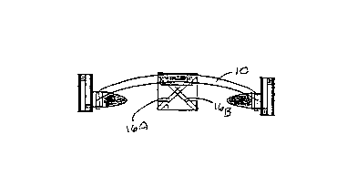
Figures lA - lC depict front, top and side views of an
illustrative stereotactic device according to one embodiment
of the invention. The stereotactic device comprises a curved
frame 10 which is worn by the subject in a manner somewhat
similar to eyeglass frames. The stereotactic device further
comprises affixing means, including a nose fitting 12 fixed to
the midpoint of the frame and a pair of ear fittings 14. In
some embodiments, the ear fittings are adjustable, slidably
mounted along the frame to accommodate the configuration of the
subject's head. The nose fitting is preferably placed on the
nasion, and the ear fittings are preferably placed in, on, or
over the ears, more preferably in the outermost portion of the
external auditory canals.
Referring again to Figure lA, the frame 10 can be of
variable length, preferably, a length of approximately 15
inches or so, and is formed into a shape providing ~or
comfortable use on a typical human adult. Such a shape may be,
e.g., a slight curve, a half circle, a "U," or the like.
Different sizes can also be made to accommodate smaller-sized
heads, such as an adolescent's or child's head.
Preferably, the materials used for making the frame are
low-cost, non-magnetic and transparent to the imaging system.
Moreover, the materials should be durable and preferably
~m~n~hle to repeated sterilization (especially when
CA 0222727~ 1998-02-17
W097/06744 PCT~S96/13956
implementing non-disposable ~rames). Preferred materials for
the frames include relatively rigid thermoplastic materials,
~ including most synthetic polymers but most preferably
plexiglass.
5.2. ~ocalizinq Means
In this aspect of the device, the frame is equipped
with localizing means comprising one or more, preferably at
least three, of what are referred to herein as localizing
arrays. Each array provides one or more imager detectable
signals from which the personal coordinate system of the
subject is derived. With the personal coordinate system
serving as the reference coordinate system for the initial,
baseline imaging scans and each subsequent follow-up imaging
scans, the stereotactic ex~min~tion of the subject is
facilitated.
In a particular embodiment of the invention, the
localizing array is made up of one or more reference elements,
preferably including a pair of reference elements. A suitable
reference element may comprise an elongate component, e.g., a
cylindrical rod or tube. Other localizing means and
corresponding localizing arrays would be apparent to one of
ordinary skill on appreciation of the disclosure provided
herein. For example, a localizing array may comprise a
supporting means, such as a cylindrical guide directed toward
the body of the subject, into which a digitizing "pen" can be
inserted. The digitizer can, in turn, emit signals that can be
observed and/or recorded on an imaging scan. Also, depending
on the number of localizing arrays, which are provided with a
frame, the reference elements can include spherically shaped,
egg-shaped, or irregularly shaped "opaque~ (more, below)
materials to create points in space.
The preferred elongated pair of reference elements can
have a number of configurations but are preferably arranged in
a spaced-apart "X~' configuration. In one embodiment of the
CA 0222727~ 1998-02-17
W O 97/06744 PCT~US96/13956
14
invention, the elongate components of each pair form an "Xn but
do not intersect. Rather, the elongate components (e.g., rods
or tubes) are staggered from one another so as to be spaced
apart. Thus, e.g., the reference elements of an array,
positioned in the proximity of, or at, the nasion, inscribe an
"Xn configuration when viewed initially from the front of the
head and form spaced apart, substantially parallel lines when
viewed from the top of the head at approximately a ninety
degree angle from the initial view. Generally, the reference
elements can 'be spaced apart by any practical distance, but
preferably range from about 0.1 to about 1 inch, more
preferably, about o. 2 to about 0.5 inch.
The reference elements are constructed or filled with
materials that produce distinctive features in an imaging scan,
such as a radiographic scan using an MR imager or CT scanner.
For example, the reference elements can be filled with doped
water, which is relatively "opaque" (i.e., give rise to
detectable signals in the course of the imaging scan) to MR, or
they can be constructed of a material that is itself opaque to
MR (e.g., stainless steel). When such a stereotactic device is
worn on, e.g., the head of, a patient being scanned, the
reference elements appear as "dots" (in the case of
cylindrical, rod-like, or spherical components) or other
distinctive features (in the case of non-cylindrical or
irregularly shaped components) ln the resulting scan.
Referring again to Figures lA, lB and lC, a localizing
means is shown comprising three localizing arrays, each array
in turn comprising paired reference elements 16A/16B, 18A/18B
and 20A/20B. The three localizing arrays are each mounted on
three ear and nose fittings, as shown. Each pair of reference
elements is arranged in the form of an "X," when viewed from
the front (tubes 16A/16B) or side (tubes 18A/18B and 20A/20B)
and is constructed from, or preferably filled with, a
radiographically detectable substance, such as doped water.
CA 0222727~ 1998-02-17
W O 97/06744 PCT~US96/13956
In cro6s-sectional, radiological scans, such as MR images,
the paired reference element tubes appear as two dots at each
fitting or location, six dots in toto. Those dots are shown in
Figures 4A and 4B, where dots a and b correspond to the cross-
sectional image of the paired reference elements 16A/16B,respectively; dots c and d correspond to the image of the
paired reference elements 20A/20B; and dots e and f correspond
to the image of the paired reference elements 18A/18B.
As stated above, the reference elements may be made of
a variety of materials or combinations thereof, including
plexiglass or other non-magnetic, radio-transparent material
that is filled with a radio-opaque substance. Alternatively,
these elements may be formed from a radio-opaque substance,
such as steel or other metal. The reference elements can be
circular in cross-section (e.g., with a radius of approximately
0.05 to approximately 0.4 inch, preferably about 0.2 inch, more
preferably about 0.1 inch) or of any other cross-sectional
shape readily discernible on a scan. Where the reference
elements are in the form of cylindrical tubes, they are
generally from about one to about five inches in length,
preferably about two inches in length.
In one embodiment of the invention, in which the reference
elements are paired, the members of each pair are generally
spaced apart from one another. This spacing may be about 0.1
to about 0.5 inch but is most preferably about 0.2 inch.
The reference elements are mounted on plexiglass or other
non-magnetic, radio-transparent support of any size suitable
for providing a supporting surface for the tubes without making
the stereotactic device unwieldy. For example, squares of
approximately one-by-one inch to five-by-five inches,
preferably about two-by-two inches, more preferably about 1.4
x 1.4 inches, are suitable for use as the support for the
reference elements. Hence, in a particular embodiment of the
invention, the combination of support and the reference
elements comprise a localizing array. In another embodiment of
CA 0222727~ 1998-02-17
W O 97/06744 . PCTAJS96/13956
16
the invention, a support may also serve as a guide for a
digitizing "pen" that can be manipulated by a physician or
technician and which generates detectable signals at locations
that can be observed and pinpointed in an imaging scan. In
still other embodiments of the invention, supports may be
dispensed with and the reference elements are found directly on
or in the frame (e.g., the elements may be an integral part of
the frame).
As used herein the term "radio-opaque" and
"radiographically opaque" refer to materials, such as doped
water, which are visible on an MRI scan or on such other
radiologic scan. Of course, a generally "opaque" material can
be chosen so that detectable signals can be observed in each,
or some, of MR, PET, SPECT, CT, MEG, or X-ray, as the case may
be, and using which material portions of the stereotactic
device (e.g., the reference elements) according to the
invention are made. Likewise, the term "radio-transparent"
refers to materials, such as plexiglass, plastics and most
synthetic polymer materials, which are generally not visible on
an MRI scan or on such other radiologic scan (e.g., PET or
SPECT), with which portions of the stereotactic device (e.g.,
the frame) according to the invention is used. Such radio
transparent materials can also be used in combination with
radio opaque materials, as would be apparent to one of ordinary
skill. It should be noted that plexiglass, plastics and most
synthetic polymers are visible, and thus opaque, in certain
imaging modalities, such as CT or X-ray.
5.3. Imaqina Procedure
To analyze a scan that includes an image of the
reference element tubes, a reference point is first defined;
most suitably, the cross-point of each pair of reference
element tubes in the above-described "X" configuration can
serve as this reference point. Assuming the image is in the
in-scan plane, e.g. as in Figures 4A and 4B, the x and y
CA 0222727~ l998-02-l7
W O 97/06744 PCTrUS96/13956
coordinates of the reference point can be found as the mid-
point between two dots on the image. The z coordinate, or the
through-plane position, is determined from the distance of the
two "dots" generated by each tube. As a result, the three-
dimensional positions of three reference points (one from eachpair of tubes) with respect to the MCS are obtained from a
single axial image. These reference points, in turn, define
the personal coordinate system.
The machine coordinates (i.e., the machine coordinate
system) can then be adjusted to rotate and translate the scan
to a predetermined plane defined by the personal coordinate
system. In this manner, the machine coordinates system can
always be made to coincide with reference points that are
independent of the machine and which are determined in relation
to the specific patient or subject. Hence, a series of imaging
scans can be obtained of the same patient at different times,
independent of the operator or the specific imaging instrument,
all of which are substantially superimposable on one another,
including the initial set or baseline set of imaging scans.
Also, images from differing imaging modalities can be "merged"
by using the stereotactic devices and methods of the invention
to provide a composite image comprising superimposed images
taken from one or more different imaging modalities.
More particularly, analysis of an imaging scan to
determine the position of the reference elements of the
aforementioned stereotactic device can be accomplished by the
methods of the invention, such as those described in detail,
below.
5.3.1. Two-Scan Exact Positioninq Method
From two or more imaging slices that cut
through both tubes of each of the three localizing arrays, the
exact location of the reference point can be calculated
mathematically as follows.
Referring again to Figure 2, points a, b, c and d are
where the two planes of the two imaging slices cut through the
CA 0222727~ 1998-02-17
W O 97/06744 . PCTAJS96/13956
18
staggered "X" (thin lines). The x, y and z coordinates in the
initial imaging coordinate system can be read from the images.
In addition, e and f are points on the tubes where the two
tubes are closest to each other, and the reference point, g,
can be defined as the mid-point between e and f. The objective
is to find the coordinates of g, given coordinates of a, b, c
and d.
Two unit vectors, parallel to each of the tubes, V1 and V3,
can be defined as:
~0
b-a
V1 = ¦b-a¦
d-c
V3 = ¦d-Cl
Also, a third vector which is orthogonal to vl and v3 can be
defined as:
V2 = Vl X V3
where x denotes the vector (outer or cross) product.
Then line segments a-e-f-d can be expressed as:
AVl + BV2 t CV3
where A, B and C are (scalar) distances between a and e, e and
f, and f and d, respectively.
Since the vector a->e + e-~f + f->d is also equal to a->d,
then V~ can be defined as:
V~ ~ d - a
CA 0222727~ 1998-02-17
W097/06744 PCT~S96/13956
19
and
Vs = [VlV2V3] B
C
Since Vl, V2 and V3 are orthogonal, A, B and C can be
obtained as:
A
B = ~VlV2V3]~lV~ = ~VlV2V3]TV4
where "T" is transpose.
The point g is:
g = a + AV1 + B V2
For the above-described computational method to work well,
the relative position of the two reference element tubes in
each localizing array must be defined by some known, non-zero
angle. The above steps are simplified by assuming that the two
tubes in each localizing array are orthogonal to each other.
However, the above-described method also works as long as two
tubes have any pre-determined, non-zero angle. In that case,
however, the inversion of [VlV2V3] becomes necessary, as will be
apparent to one skilled in the art.
It is further preferable for the sake of simplicity in
calculating the scan position to have the angles between the
tubes in each localizing array to be the same. Again, however,
this is not critical under the practice of the invention so
long as the angles of the tubes in each localizing array are
known.
CA 0222727~ 1998-02-17
W O 97/06744 PCTAUS96/13956
5.3.2. Sinqle-Scan Positionina Method
It is also possible to determine the
position of the reference point from a single slice relatively
accurately, although mathematically not exact. As6uming the
imaging scan is in the x-y plane, the x and y coordinates of
the reference point can be found as the mid-point between two
dots on the image. The z coordinate, or the through-plane
position, can be determined from the distance between the two
dots. Since the two tubes are arranged in a staggered "X"
configuration, the direction in the z axis can be determined
knowing the angle between the elongated components. As a
result, the positions of three reference points in all three
dimensions are obtained from a single axial image.
Referring now to Figure 3, points a and b are where the
imaging plane (thin line) cut through the staggered "X" (thick
lines). The distance D is defined as the distance between the
points a and b on the image and corresponds to the distance
between the two tubes that make up the "X" of the localizing
array. The x and y coordinates of the reference point, m, can
be found on the image as the midpoint between the dots. The z
coordinate of the reference point, z, can be calculated as:
5.3.3. Com~utational Method
30The detailed calculation method for
determining the orientation of a patient's head is as follows:
Let pl, p2 and p3 be vectors representing three reference
points in the initial image coordinate system corresponding to
a/b, c/d and e/f in Fig. 4A, respectively. These points are
calculated as described above. Then, unit vectors representing
the new, desired personal coordinate system, x, y, z, can be
calculated as:
CA 0222727~ 1998-02-17
W O 97/06744 PCTAUS96/13956
x = p3 - p2
z _ x x (pl - p2)
y = X X Z
where xdenotes the vector product operation. A rotation matrix
that rotates these into xyz axes is obtained as:
R = yT
where "T" is transpose and the translatio15
p2 ~ p3
t = - R 2
A general diagnostic method according to the invention is
outlined in Figure 5, including determining a standard
reference coordinate system that is based on the personal
coordinate system. First, a stereotactic device, as described
above, is placed on the patient. Next, the patient is placed
in the imaging device while wearing the stereotactic device.
The patient position is adjusted so that an axial image cuts
across all tubes in at least three localizing arrays. A scan
is taken subsequently. An exemplary resulting scan is shown in
Figure 4A.
From such a scan, the three patient reference points of
the personal coordinate system are calculated as described
above. From these points, a rotation matrix and a translation
vector are calculated to adjust the initial imaging coordinate
system to the personal coordinate system, as defined by the
stereotactic device. On the MR imager, these transformations
are applied to the gradient fields, receiver frequency and
phase to change the machine coordinate system.
Next, another axial imaging scan is obtained in the new
standard reference coordinate system and the "dots" are checked
to ensure that the "dots" are aligned at the predetermined
CA 0222727~ 1998-02-17
W O 97/06744 . PCT~US96/139~6
positions. The scan of Figure 4A, modified in accord with this
method of the invention, is shown in Figure 4B.
Once a standard reference coordinate system is determined
by the foregoing steps, then a full set of ~AminAtions is
obtained using the defined rotation matrix and the translation
vector. The entire image alignment process can be performed in
a minimal time as compared to previously known scanning
techniques in which an attempt is made to adjust or fix the
patient coordinate system each time relative to the coordinate
system of the imager.
5.4. Additional Sup~ortinq Disclosure
A still further aspect of the invention provides a
stereotactic device for non-invasive stereotactic ~AminAtion,
particularly of the head of a subject, comprising a frame that
is reproducibly positioned on the subject. The frame may have
any number of localizing means comprising radio-opaque
reference elements to provide for a multi-dimensional reference
coordinate system. In a preferred embodiment, six reference
elements are included, which are arranged in pairs to provide
three localizing arrays.
The frame of the stereotactic device is preferably made
of a non-radiographic material, preferably plexiglass. Other
suitable radio-transparent materials include, but are not
limited to plastics, synthetic polymers, or other carbon-based
materials of some structural rigidity, such as poster board,
cardboard, or even graphite.
In a particular embodiment, the frame provides a three-
dimensional framework for the at least four reference elements
to provide a three-dimensional personal coordinate system. In
such an embodiment, the localizing means comprises four or more
localizing arrays each comprising a reference element. Each
reference element, in turn, defines a point in space, three of
which points define a unique plane and the fourth point lying
outside the unique plane.
CA 0222727~ 1998-02-17
W O 97/06744 . PCTrUS96/13956
23
In yet another embodiment three reference elements can be
designed into the device to provide inherently the fourth
reference element necessary to define a three-dimensional space
(e.g., as described earlier, confining two of the three
~ 5 reference elements to a pre-determined plane).
The reference elements are positioned on the frame at
predetermined positions to provide the three dimensional
coordinate system. As described above, the reference elements
can be paired in an orthogonal arrangement and be constructed
or filled with materials that produce "dots" or other
distinctive features in an imaging scan plane. These elements
make up the localizing means that provides a reproducible
localization of the multi-dimensional personal coordinate
system. Thus, the reference elements may include markings such
as small paint spots, indentations, slots, grooves, and the
like, in or on the frame whose positions can be entered into or
recorded in a scan via, e.g., an MRI-compatible digitizer.
Hence, in a preferred embodiment of the invention a
stereotactic device for use with an imager comprises a frame
equipped with localizing means and affixing means. The
localizing means comprises three or more localizing arrays each
equipped with two or more reference elements that together
provide six or more imager detectable signals. The affixing
means comprising three or more non-invasive fittings for
placement on the subject's nasion and in or about the subject's
ears. The fittings, together, permit the reproducible
positioning of the frame on the subject and the reference
elements each provide an imager detectable signal. The personal
coordinate system is then derived from these signals,
collectively.
The reference elements preferably comprise elongate
components. For example, two elongate components are arranged
in an "X" configuration and are related to one another by a
predetermined angle, e.g., about 90 degrees. Further, the
reference elements comprise radiographically opa~ue or semi-
CA 0222727~ 1998-02-17
W O 97/06744 PCTAUS96/13956
opaque material, including steel or doped water. The signals
obtained from the reference elements are preferably detectable
by MR, CT, PET, SPECT, EEG, or MEG. In an alternative
embodiment, the imager detectable signals are provided by a
digitizer used in conjunction with the one or more localizing
arrays.
The preferred device may further comprise a securlng means
that facilitates the securing of the frame to the subject.
Such securing means may include an inelastic or elastic
component.
In use, the stereotactic device is reproducibly positioned
on the head of a subject. The position of the reference
elements with respect to the desired location of the subject is
then digitally recorded, e.g., with an MRI-compatible
digitizer. The digitized positions of the reference elements
provides a reproducible personal coordinate system.
Subsequently, the positional rotation and translation
necessary to bring the machine coordinate system into alignment
with the personal coordinate system can be determined,
preferably by a digital processor. After the machine
coordinate system is adjusted to align with the personal
coordinate system, one or more radiographic scans are taken.
In subsequent scans, the patient again reproducibly dons
the stereotactic device and the positions of the reference
elements are digitally recorded. The second imager is then
adjusted to the personal coordinate system by means of a
translation and/or rotation of the second imager's machine
coordinate system, as above. The second and subsequent scans
are then taken, again in the patient coordinate system. By
scanning each time in the patient coordinate reference system,
all scans can be directly compared.
Described above are improved devices and procedures for
non-invasive, radiographic analysis, particularly stereotactic
head exAm;n~tions, e.g., in connection with stereotaxy or other
similar surgical procedures, meeting the objects of the
CA 0222727~ 1998-02-17
W O 97/06744 PCTAJS96/13956
invention. Some of the more noteworthy features of the
invention include, but are not limited to:
- 1. A stereotactic device that can be made with extremely
low cost and which can be made in disposable or re-usable form;
2. A method of aligning the imaging plane in which only
one axial image through the device is necessary to perform the
subsequent alignment; the only human intervention required is
the identification of the reference points ("dots") of the
personal coordinate system on the localizing axial image; the
rest of the process can be implemented in the imagery and
processed automatically; moreover, with an automated mechanism
to identify the "dots," the entire process can be fully
automated;
3. Imaging scans acquired according to the invention are
alignable to a reproducible reference coordinate system, so
that the images from different e~min~tions can be compared
directly; these examinations could be performed at different
institutions, with different imagers, etc., as long as all
~x~min~tions are taken with a device of the invention
positioned on the subject;
4. A device and method best used in obtaining MR images;
however, other imaging modalities, such as CT, PET, SPECT, or
MEG, are also applicable; these other imaging modalities can
then be cross-referenced with MR imaging scans.
The stereotactic device of the invention is exemplified
as an eyeglass-like structure. However, the invention may be
of any suitable structure that can support the localizing
arrays or reference elements and which can be reproducibly
positioned on the subject. Hence, the invention provides a way
of mapping an anatomical region of a subject which can be
related to a personal coordinate system that is independent of
the machine coordinate system. Furthermore, the device and
methods of the invention may also be amenable to veterinary
applications.
-
CA 0222727~ 1998-02-17
W O 97/06744 . PCT~US96/13956
It should thus be apparent that the present invention
provides a method of obtaining imaging scans of a subject
comprising the steps of: providing a subject with a non-
invasive stereotactic device that is positioned reproducibly on
the subject and which establishes a personal coordinate system
(PCS). The PCS is associated with the subject independent of
a machine coordinate system (MSC) that is associated with an
imager; taking, using an imager having an MCS, an imaging scan
of the subject including the stereotactic device to establish
the PCS of the subjecti manipulating the MCS of the imager to
bring the MCS in substantial alignment with the PCS of the
subject; and taking one or more additional imaging scans of the
subject with the MCS of the imager substantially aligned with
the PCS of the subject, to obtain a first set of imaging scans.
The method of the invention may further comprise repeating
the above-mentioned steps at a second time period, using a
second imager, to obtain a second set of imaging scans.
Subsequently, at least one imaging scan of the first set can be
compared with at least one imaging scan of the second set. In
this way, an operator has the opportunity to note and make a
record of any previously undetected anatomical feature of the
subject. Moreover, observations can be made of any changes in
any previously detected anatomical feature of the subject. As
mentioned above, such anatomical features may be of anything
that can be of interest to the subject or the medical
practitioner, including but not limited to lesions, tumors, or
features that may indicate a pathological condition.
Adventitiously, the stereotactic device is positioned
reproducibly on the subject's head.
The second time period of the disclosed method represents
an elapsed time from the taking of the first set of imaging
scans to the taking of the second set of imaging scans. This
elapsed time may, of course, be any time period appropriate to
the ~min~tion process, including periods that are very short
(e.g., essentially back-to-back scans), intermediate (e.g.,
CA 0222727~ 1998-02-17
W O 97/06744 PCTAJS96/13956
days to weeks), or very long (e.g., years). For instance, the
elapsed time period may be about 15 to about 45 minutes, a few
hours, one day to about one week, about one week to about one
month, about one month to about six months and about six months
- 5 to about one year. This second time period may even represent
an elapsed time from the taking of the first set of imaging
scans to the taking of the second set of imaging scans of about
one year to about five years.
Separately, the invention provides a method of obtaining
imaging scans of a subject comprising the steps of (a)
providing a subject with a non-invasive stereotactic device
that is positioned reproducibly on a subject and which
establishes a personal coordinate system (PCS) associated with
the subject which is independent of a machine coordinate system
(MSC) associated with an imager; (b) taking, using a first
imager having a first MCS, at least one imaging scan of the
subject including the stereotactic device to establish the PCS
of the subject and to relate the PCS of the subject to the
first MCS of the first imager; (c) taking, using a second
imager having a second MCS, at least one imaging scan of the
subject including the stereotactic device to reestablish the
PCS of the subject and to relate the PCS of the subject to the
second MCS of the second imager; and (d) manipulating the
second MCS, such that the PCS is related to the second MCS in
substantially the same way as the PCS is related to the first
MCS.
In this method of the invention, the second MCS is
substantially aligned with the first MCS. In a specific
embodiment, the first imager may be an imager in which the
machine coordinate system cannot be adjusted to the personal
coordinate system (i.e., the machine coordinate system is
fixed, as with a CT scanner). If so, the second imager is one
whose machine coordinate system is adjustable, preferably, an
MR imager. The method involving different imaging modalities
may further comprise forming a composite image including
CA 0222727~ 1998-02-17
W O 97/06744 PCT~US96/13956
28
information from at least one imaging scan taken using the
first imager and information from at least one imaging scan
taken using the second imager.
In addition, the present invention also relates to a
method of spatially aligning at least two radiographic imaging
scans of the head of a subject taken by a radiographic scanning
device comprising: (a) radiographically scanning the head of a
subject wearing a stereotactic device of the invention to
provide a first radiographic imaging scan containing a
plurality of reference points defining a first personal
coordinate system; (b) relating the first personal coordinate
system with a personal coordinate system obtained from a prior
radiographic imaging scan of the subject reproducibly wearing
the stereotactic devicei (c) adjusting the radiographic
scanning device to align the first and prior personal
coordinate systems; and (d) obtaining one or more additional
radiographic imaging scans of the subject with the radiographic
scanning device so adjusted.
The following additional examples are provided to further
illustrate preferred aspects of the invention. Nothing in
these additional examples should be construed to limit the
invention in any way.
6. Exam~les
6.1. General Method
In a generic embodiment of the invention, a pulse
sequence to rotate the imaging coordinate system is executed on
a clinical MR imager (e.g., a 1. 5T Signa, GE Medical Systems).
The rotation matrix is determined by a conventional digital
data processor (e.g., a personal computer) programmed to
calculate the rotation matrix from the positions of the
reference points of the frame. A listing of the relevant
computer programs are attached hereto, as Appendices A and B.
CA 0222727~ 1998-02-17
W O 97/06744 PCT~US96/13956
Those skilled in the art will appreciate that rotation of
the imaging coordinate system and determination of the rotation
matrix can be implemented on the image as a single step. In
that case, the necessary operation is reduced to identifying
the positions of the reference points (e.g., 6 points in a
specific embodiment) on the first image. Hence, the required
sophistication of the technologist is greatly reduced by the
inventive method.
6.2. Use of an MRI-~om~atible Diqitizer
In a specific embodiment of the invention, the
reference points in the first scan are entered into a digital
data processor by means of an MRI-compatible digitizer. In
this embodiment, the technologist need only mark the position
of the reference elements on the first scan and the digital
data processor calculates the patient-defined personal
coordinate system from the digitized entries using, e.g., the
computational examples given above.
6.3. Use of Electrodes for Determining Brain
Structures
In yet a further embodiment of the invention, the
correlation of electrical activity in the brain with specific
brain structures may be reproducibly accomplished. In this
embodiment, an MR imaging scan is taken of the patient wearing
the stereotactic device to obtain a "baseline" scan. (It
should be noted that as long as the device of the invention is
worn, the baseline scan may be taken before or after the EEG.)
An EEG is then taken of the patient, with the device in
place. One or more electrodes, typically 15-30 electrodes, are
then positioned on the head of the patient. The position of
each of the electrodes is then entered into a digital signal
processor, e.g., as described above, to define the electrode
CA 0222727~ 1998-02-17
W O 97/06744 PCTAUS96/13956
positions with respect to the patient coordinate system as
defined by the device.
If any aberrant, unusual, or abnormal traces are observed
from the EEG, the identity and position of the electrode or
electrodes giving rise to such traces can be determined. The
MR imager is subsequently utilized to provide an imaging scan
across the positions of the electrodes of interest. One or
more scans are taken to obtain images of the patient's anatomy,
which may give rise to the aberrant traces. Through this
alignment technique, electrical signals detected by the
electrodes can be correlated with particular brain structures
to a high degree of accuracy and reproducibility.
6.4. Follow-U~ ElectroencephaloqraphY (EEG)
The general positions of each electrode can be
reproduced, if desired, to correspond with an initial EEG,
using the device of the invention. Alternatively, each new
configuration of the electrodes can be recorded digitally
relative to the PCS established by the device, and MR images
can be taken selectively based thereon.
When seeking a reproducible placement of electrodes for
use in electroencephalography (EEG), a series of MR imaging
scans is taken of a patient wearing the stereotactic device of
the invention, as described above, to establish the personal
coordinate system. One or more electrodes are then placed on
the patient's head, and the position of the electrodes is
digitized, as described above. The location of the electrodes
is thereby determined and recorded relative to the personal
coordinate system.
Upon subsequent EEG ~ mln~tions, the patient wears the
stereotactic device of the invention. One or more scans are
taken to reestablish the personal coordinate system. One or
more electrodes are again placed on the patient so that their
positions correspond to their original positions in the initial
3 5 EEG/MRI scan. Correct placement of the electrodes is checked
CA 0222727~ 1998-02-17
W O 97/06744 PCTAUS96/13956
31
by comparing the prior scan and electrode placement with that
of the subsequent scan.
Accordingly, any changes in the electrical activity of the
patient can be attributed to specific electrodes and/or patient
- 5 anatomical features as revealed by the MRI.
6.5. Imaqina Across Different Modalities
A further aspect of the invention provides for the
direct comparison of imaging scans taken with different
modalities, particularly wherein at least one of the modalities
has a coordinate system that is not adjustable. In this
embodiment, e.g., a first scan ha~ing fixed machine coordinates
is taken of the subject wearing the stereotactic device of the
invention. The reference elements are located in the scan and
a personal coordinate system is established therefrom.
Additionally calculated is the translation and rotation of the
machine coordinate system required to align the machine with
the personal coordinate system.
A second scan is later taken with a modality in which the
machine coordinate system can be adjusted (e.g., MR imager)
with the patient reproducibly wearing the stereotactic device.
The reference elements are identified in the second scan and
the personal coordinate system determined. The value of the
difference in the personal coordinate system and the machine
coordinate systems for the initial and second scans are
determined.
With the common personal coordinate system in place, the
second imager is then adjusted to translate and/or rotate the
second imager coordinate system so that the difference between
the second image coordinate system and the second personal
coordinate system coincides with the difference between the
first image coordinate system and the first personal coordinate
system.
Subsequent scans are then taken with the second imager
aligned with the scan plane of the first imager, permitting a
CA 0222727~ 1998-02-17
W O 97/06744 PCTAUS96/13956
highly reproducible direct alignment of scans taken in the two
different modalities based upon the common personal coordinate
system.
The stereotactic device and procedure of the invention can
thus be used to align images from modalities such as computed
tomography (CT), positron emission tomography (PET), single
photon emission computed tomography (SPECT), electro-
encephalography (EEG) or magnetoencephalography (MEG), and the
like.
In the case of CT and the device of the invention, an
illustrative procedure is as follows (NB: It is not possible to
freely position the CT slice, hence, MR images have to be
rotated to the CT plane.):
First, the CT ~Am~nAtion is done with the device on. The
position of the reference points (mid-point of the X-shaped
rods) in the CT coordinate system is calculated. Next, an MR
axial slice through the device is taken, and the MR coordinate
system is rotated/translated to coincide with the CT coordinate
system, i.e., the second machine coordinate system is
substantially aligned with the first machine coordinate system.
Imaging slices that are of the same location/thickness as those
of the CT ~AmlnAtion are then taken.
As is readily evident to those skilled in the art, similar
procedures can be employed for aligning other imaging
modalities. In this way, all imaging capabilities can be
linked through the use of MR under the practice of the
invention.
6.6. Pxocess for Determininq Subiect Head Orientation
Still another aspect of the invention provides a
method for determining the orientation of a subject's head.
The procedure includes placing a plurality of, preferably
three, localizing arrays of the "X"-type, described above,
about the head of a subject patient, e.g., substantially
adjacent the nasion and ears, or in other locations spaced
CA 0222727~ 1998-02-17
W O 97/06744 . PCTrUS96/13956
33
apart about the circumference of the head. The procedure
further includes taking a cross-sectional imaging scan of the
head in the vicinity of the localizing arrays and determining
the orientation of the head based on the pattern of "dots" (or
other distincti~e features generated by the reference elements)
in the imaging scan. This operation may be accomplished
conveniently through use of the computer-implemented program
appended hereto. Adjustments to the orientation of the
subject's head can then be performed as needed or desired.
6.7. Further Examples
The stereotactic device and the correction procedure,
described above, are used with both phantoms and human
volunteers. The standard quadrature head coil is used for
taking the imaging scans.
Figures 4A-4B show a typical set of imaging scans, which
is acquired with a volunteer. As noted above, Figure 4A is the
initial axial image taken through the device, and Figure 4B is
the image taken after the manipulation step, e.g., the rotation
and translation steps, is applied. All three pairs of dots are
aligned with each other, indicating the imaging plane is now
cutting through the three reference points. Also, the
reference points are at the pre-determined locations.
To demonstrate the reproducibility of the method, the
following study is carried out: First, the device is positioned
on the volunteer, and the first axial MR slice is taken.
Rotation/translation correction is applied and a set of
multi-slice images is taken. The volunteer is withdrawn from
the magnet. The device is removed, and replaced again on the
subject by a different technologist. Images are taken again in
the same manner as in the first scan set.
Several slices from these two e~min~tions are shown in
Figures 6A and 6B. Figure 6A shows the images taken by the
first operator, and Figure 6B shows the images taken by the
second operator. (Imaging parameters are: modified RARE
CA 0222727~ 1998-02-17
W O 97/06744 PCTAUS96/13956
34
sequence, 30 cm FOV, 256 x 256, 3 mm slice, single slice axial
scan (Figures 4A and 4B) and multi-slice axial scan with 20 cm
FOV (Figures 6A and 6B).)
As is evident from these pictures, a high degree of
reproducibility in scan sections is provided by the device and
method of the invention.
The accuracy in reproducing slice position and orientation
between different time points is evaluated in phantom and human
volunteer studies. The error in phantom studies, when using
the mathematically exact, two-scan method, is about 1 mm or
less! In human volunteer studies, the error is somewhat higher
due to patient motion, though still readily acceptable for use
in comparison of the sizes and locations of lesions from one
exam to another. In particular, the device of the invention
allows for routine scanning, in part because of the little time
(2 to 3 minutes) required for device positioning, reference
scanning and determination of reference points.
Those skilled in the art will appreciate that the
embodiments described above are exemplary and that other
embodiments incorporating alterations and modifications therein
fall within the scope and spirit of the invention. Each of the
references mentioned above is incorporated by reference herein.