Note: Descriptions are shown in the official language in which they were submitted.
CA 02227393 1998-01-20
Fireplace Burner Apparatus
Field of Invention
This invention relates generally to a combustion appa~ s having a visible fire display, and
more specifically to burner manifolds and displays for gas fireplaces. In particular it relates to such
gas burner manifolds as may present an array of burner jets oriented generally toward an
arrangement of ~im~ ted solid fuel materials, and most particularly those manifolds for use with
a ~im~ ted wood log display having more than one level and which may include embedded
o emberizing material disposed for interaction with burner exhaust gases.
Barkground Art
Gas fireplaces generally include a casing for cont~ining the fire, a firebox mounted within
the casing in a manner which permits air from inside a dwelling to circulate thereabout and be
warmed, a gas burner for connection to a gas supply, and an arrangement of sim~ ted solid fuel
material located relative to the burner in a manner which gives an aesthetically pleasing natural
fire appearance when in use. The casing and firebox are provided with an opening and a window
respectively, by which means persons may view the fire. In some instances the sim~]l~ted solid fuel
is arranged to have the appearance of a coal fire, or bed of coals. In North America ~im~ ted
wood log fires predominate.
The nature of ~imlll~ted fire displays is such that it may be advantageous to locate the
~im~ ted logs in a generally rearwardly ascending display such that more of the fire is visible.
2s Most commonly the .cimlll~ted logs are arranged in a tier-like fashion. However the logs or coals
may be arranged, it is generally desirable to produce a corresponding flame display in a manner
which gives the appearance of the entire log set burning. The careful m~tçhing of burners to
~imlll~ted log or .cimlll~ted coal arrangements to produce aesthetically pleasing results is a science
of much subtlety.
It is known to direct gas jets against ~imlll~ted log or ember ma$erials to ~imlll~te the
appearance of glowing coals, and that cooler ~ames have a more yellow appearance similar to the
appearance of a natural wood fire. However, it is also known that directing flames to impinge
upon relatively cool high thermal mass ceramic or concrete logs may lead to incomplete
20431586.1
CA 02227393 1998-01-20
combustion, sooting, and unacceptable pollutant emissions. One technique used to produce
~im~ te~ glowing embers is to place a gas manifold in or beneath a bed of emberizing material,
such as low density rock wool. Another technique is to direct flames at soft ceramic material,
whose surface then glows. In either case a stable flame pattern may yield a constantly glowing
s body rather than a flickering effect.
The production of a glowing portion of a log, or an ember strip, or a bed of ~im~ te~
glowing coals often requires the careful pl~cP.mPnt of ember ~im~ ting materials relative to flames
em~n~ting from a burner. In some instances the glowing material is loosely deposited on the
10 burner itself, or in a tray about the burner. The glow produced may also vary on the in~t~llation
of a log set on delivery, a relatively small change in the spacing between logs, or their relative
angles of placement, may result in an unexpected hot or cool spot. It is advantageous to control
the relative dimensions of a(ljacçnt glowing and non-glowing elements to reduce the likelihood
of such unexpected results.
The problem of rearwardly ascPn~ing logs may be addressed by providing a real wardly
a~c~.nt1ing burner, such as the two-run U-tube burner in U.S. Patent 5,081,981 issued January 21,
1992 to Beal. or the H-shaped welded burner of U.S. Patent 5,052,370 issued October 1, 1991
to Karabin. Another alternative is to employ fore and aft burners, as in U.S. Patent 5,388,566
20 issued February 14, 1995 to Smith et al.
A disadvantage of such tube run burners is that they may yield the appearance of a straight
line, or curtain of flame, rather than a more random natural appearance. One attempt to give a
more random effect is shown in U.S. Patent 5,392,763 issued February 28, 1995 to Shaw et al.,
2s in which each of a plurality of pipes having a plurality of openings follows a twisted path to a
desired location. Another attempt to give a more random flame distribution is to use a pan burner
with more randomly located oper~ings, be they pinholes or slots, designed to match a less tier-like
log set, such as is shown in U. S. Patent 4,726,351 issued February 23, 1988 to Whittaker et al.,
or C~n~rli~n Application 2,139,096 of Squires et al., laid open June 24, 1996.
As noted above, it may be desirable to have a burner flame port in a configuration other than
a pinhole. Holes formed by drilling, piercing, slitting, laser cutting and other conventional means
20431586.1
CA 02227393 1998-01-20
are well known. The aspect ratio of a slot is defined as the ratio of its characteristic length to its
characteristic width, whether those characteristic dimensions are the length and width of a
rect~n~ r slot, the arc length and width of a non-linear slot, or the major and minor axes of an
oval or elliptical slot. The repeated heating and cooling cycles of pan burners, often with local hot
s and cool spots, may lead to d~r~ ~lion ofthe burner, and in particular, to deformation of the top
sheet ofthe burner over time. An appalelllly minor distortion ~djacçnt to an high aspect ratio slot
may yield undesired changes in the flame patterns, and pollllt~nts, produced. It is advantageous
not only to m~int~in the geometric relationship of the various heated and glowing members, but
also to m~int~in slot geometry.
0
It is known to provide pan burners with internal baffling, brackets, top hat sections, and
even dead air-space walls. This has the disadvantage of increasing the number of parts required
and the number of assembly operations, and it is generally desirable to avoid a large number of
internal parts. The use of drawing and punching techniques before assembly reduces the need for
s extra parts, and per~nits local stiff~.ning ofthe burner panel adjacent particular burner ports as may
be desired. Notably, while a flat plate can be punched or drawn easily, it is rather more difficult
to produce an outward blister or rib in a tube burner.
Although pan bumers have been decign~d for modest angles of inclination, the design of gas
20 manifolds to deliver combustible gas at di~ levels within a firebox requires some care in light
of buoyancy effects. A combustible gas, such as natural gas, less dense than the surrounding
ambient air will have a tendency to collect in the highest regions of the burner first, and may resist
distribution to lower regions. Conversely a gas of greater density, such as propane, may pool in
the lower regions of a burner, and produce an lln.c~ti~f~ctory flame pattern at raised locations.
2s Restriction of port size in one area of a burner to offset buoyancy effects may also limit the ability
to produce a desired appearance at that, or other locations. Such a restriction may also not be
advantageous for a change to a fuel of di~elelll density, or to a dirrelelil proportion of primary
air.
Single inlet gas burners are well known. One disadvantage of such burners is that, by their
na~re, they deliver only one mix of combustion gases for all parts of the burner. The mix of gases
delivered depends on the extent to which primary air is introduced into the gas stream. Typically,
20431586.1
CA 02227393 1998-01-20
the amount of entrained primary air is controlled by a valve between the gas supply main and the
manifold. At present the mix is uniquely determined for the entire bumer by the setting of that
valve. However, one may wish to use a relatively rich fuel mix in some regions of the burner, and
a lean mix in others. In the one case a large, more yellow flame may result, in the other a hotter
s flame may be desired for heating ember materials to produce a glow.
It is known, as for example in Whittaker, above, and in U.S. Patent 4,305,372 issued
December 15, 1981 to Hahn, to use two separate gas manifolds, each with its own inlet. Hahn
pemlits the use of separate valves to control bumers for cooking. In these bumers the
o introduction of gas into each separate burner chamber has no effect on the distribution in any of
the other bumer chambers.
There is, therefore, a need for an improved burner and display appala~-ls for gas fireplaces
and similar devices.
Summary of the Invention
In one aspect of the present invention there is a gas burner comprising a body having an
internal plenum; an inlet for receiving gases from a source of combustion gases, the inlet in fluid
20 communication with the plenum; and an outlet from the plenum, the outlet having an at least
partially reh~orced periphery. In further aspects of the invention the gas burner body has a wall
thickness, the outlet includes a protrusion e~ctending outwardly from the plenum, the outlet
in~ des an aperture having a characteristic width and a characteristic length, and the bumer meets
at least one of the criteria chosen from the group consisting of:
2s a) an hydraulic diameter of the aperture of less than the quotient obtained by dividing
the length of said periphery by ~.
b) the protrusion extends outwardly of the body a distance in the range of 0.7 to 20 times
the wall thickness;
c) the protrusion extends outwardly ofthe body a distance in the range of 0.5 to 50 times
the char~cteristic width;
d) the outlet is de~ign~d for a gas burner port loading in the range of 7000 to 60,000
BTU/Ilr per square inch;
20431586.1
CA 02227393 1998-01-20
e) the outlet is de~ .d, at ISA ~t~ldald conditions, for a mean exit gas velocity greater
than 12 inches per second; and
f) the outlet is an elongate aperture having an aspect ratio of length to width in the range
of 2 to 200.
Tn another aspect ofthe invention there is a burner co~ .l ;.c;i~g a body having a plenum contained
IL~ ~il~, an inlet for delivering combustible gases from a supply of combustible gas to the plenum;
the plenum having a first region, a second region and a third region between and in fiuid
comml-nication with the first and second shelf portions; the intermediate portion canted with respect
0 to each of the first and second shelf portions; the first and second shelf portions each having at least
one opening for p~rmitting egress of the gas from said plenum. Tn a further aspect of the invention
each ofthe first, second and third regions has a length and a width defining respective first, second and
third planes; the first plane intersects the third plane; and the third plane "llel~e~;Ls the second plane.
In yet another aspect of the invention there is a bumer coll,~ ing a body having a plenum
col l~ d therewithin; a first inlet for delivering combustible gas from a supply of combustible gas to
the plenum; and a second inlet for delivering combustible gas from a supply of combustible gas to the
plenum, the plenum having at least one opening for pemlitting egress of the gas from the plenum. Tn
still another aspect ofthe invention at least one ofthe first inlet and the second inlet is provided with
20 a valve for ~mitting primary air whereby the ratio of combustible gas to the primary air delivered by
the first inlet to the plenum may be di~l~ from that delivered by the second inlet. Tn a yet further
aspect of the invention the plenum has a first region and a second region in fiuid communication
therewith; each ofthe first and second regions has at least one opening for p~.rmitting egress ofthe gas
from each respective region of the plenum; the first inlet being located to deliver combustible gas to
2s the first region; the second inlet being located to deliver combustible gas to the second region. Tn
another aspect the plenum COI "l ~ i~c a third region intP.rme~ tç7 and in fluid communication with, said
first and second regions, the third region being canted relative to each of said first and second regions.
Tn a final aspect ofthe invention there is a simlll~ted solid fuel element for co-operation with a
30 burner of a gas fireplace, said ~imlll~ted solid fuel element complising: a body having at least one
surface fommed to ~imlll~te the appearance of a real solid fuel eleme~t; the body having at least one
filament secured thereto, that fil~m~nt extending outwardly of the surface for interaction with exhaust
20431586.1
- - -
CA 02227393 1998-01-20
gases from the burner, whereby the exhaust gases from the burner may heat said fil~mPnt to
in~.~nt1escPn~e. In associated aspects of the invention the solid fuel element meets at least one of the
conditions chosen from the set consisting of:
a) the solid fuel element is in the form of a log;
s b) the surface includes a ~im~ ted charred area and the filament extends outwardly from
the ~imlll~ted charred area;
c) the fil~mPnt is part of a skein of fil~mPnt~ having a root embedded in the body;
d) the fil~mPnt has at least one end integrally molded into the body;
e) the fil~mPnt is formed from a material chosen from the set of
0 i) stainless steel,
ii) steel wool,
iii) rock wool, and
iv) spun glass;
f) the filament has a (li~meter in the range of 0 0002 inches to 0.020 inches;g) the flament extends outwardly from the surface a distance in the range of 0.040 to 0.500
inches;
h) the filament is one of a plurality of ~ in a nlament array, that array having a mean
random filament density in the range of 2 to 20 fil~mPnts per square c~ ;" ~
i) the filament is part of a strand located in a channel set in the surface of the solid fuel
PlPmP~nt
B~ef D~c, ;ylion of the D~
Figure 1 is a general arr~ngPmP,nt view of a fireplace assen~ly suitable for incorporating an
2s embodiment ofthe present invention.
Figure 2 is aview on cross section '2-2' ofthe fireplace assembly of Figure 1 with a burner and
~imlll~ted log display installed therein.
Figure 3 shows a front view ofthe log display of Figure 2.
Figure 4, being Figures 4a, 4b, 4c, and 4d, shows, ~ ec~ ely, top, front elevation, profile and
30 quarter views ofthe stepped pan burner of Figure 2.
Figure 5, being Figures 5a, 5b, 5c, and Sd, shows four ~ltern~tive embodiments of burner port
stiffening for the stepped pan burner of Figure 4.
20431586.1
CA 02227393 1998-01-20
Figure 6, being Figures 6a and 6b, shows details of the pl~cPmPnt of fil~mP.nt~ relative to one
embodiment ofthe log set of Figure 3.
Best Mode for Carryin~ Out the Invention
In the description which follows, like parts are marked throughout the specification and the
drawings with the same le~e~ e reference numerals. The drawings are not necess~rily to scale and
in some in~t~ncP~s proportions may have been exaggerated in order more clearly to depict certain
features of the invention.
Referring to Figs. 1, a gas fireplace assembly is shown generally as 10. It has a firebox, 12,
having sidewalls, a rear wall, a top wall with ~ue, and a front opening to permit viewing of a fire
ther~will~ill. Firebox 12 has a fioor 14 on which to mount a bumer, fioor 14 having an opening 16
therein suitable for receiving a burner and associated control hanlw~. The control hardware and gas
5 train are not shown. They are of conventional design and are ultimately comle-;led to an external source
of comhl-~tion gases. Firebox 12 is carried in a casing 18, also having sidewalls, a rear wall, a top wall,
a bottom wall a fiue, and a frontal opening for p~llllilling both the in~t~ tion of firebox 12 and the
viewing of a fire therein. Although a conventional fiue fireplace is shown, and the fire draws its
comhu~til n air from room ambient, the use of a direc~y vented firehox having external air intake would
20 not alterthe nature ofthe present invention. Firebox 12 is suspended within casing 18 in a marmer to
leave an ambient room-air passage 20 by which room air circulating thelethrough may be heated.
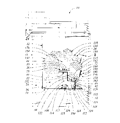
Gas fireplace assembly 10 is shown in cross section in Figure 2, with a burner assembly 22, and
a ~imlll~ted fire display in the nature of a ~imlll~ted soft ceramic log set 24 located thereupon. The
2s ~imll1~ed fire display could be a ~imlll~ted coal fire and could be of higher density ceramic, concrete,
or other suitable material. Burner assembly 22 is provided with support structure in the nature of a
burner tray 26, for location upon firebox ~oor 14. Burner assembly 22 in~llldec a burner manifold 28
in the form of a stepped pan burner 30. Stepped pan burner 30 is supported by left and right hand angle
brackets 32 affixed to tray 26
20431586.1
-
CA 02227393 1998-01-20
_ 9 _
Burner manifold 28 has a body 34, in the form of a sheet metal shell 36, with an internal plenum
38 contained therewithin, itselfhaving a first inlet 40, and a second inlet 42 which receive combustible
gases from the conventional gas control and gas train noted above; a first region in the nature of a first
shelf portion 44; a second region in the nature of a second shelf portion 46; those first and second
s regions being in mutual fiuid communication via a third region 48, being an intermediate portion, in
the nature of a perp~n~ r riser 50 between and in fiuid communication with said first and second
shelfportions 44 and 46. Each of first and second shelfportions 44 and 46 is provided with at least one
operling for pr~ the egress of combustible gas lhel~om in the form of a gasiet such that~ when
lit, the jet will produce a flame within firebox 12 in the neighbourhood ofthe ~im~ ted fire display of
0 log set 24. For example, in the embodiment illustrated in Figure 4, shelf portions 44 and 46 are each
provided with respective burner port arrays 52 and 54. Intermediate portion 48 need not be
p~ ellJicular to shelf portions 44 and 46, and may itself have one or more openings for pel " ,; ~ g the
egress of combustible gas to produce a desired flame pattern. In the embodiment shown, the
;"~ le por~on is provided with a linear array of flame carry-over ports 56 to provide an ignition
path between array 52 and array 54. A pilot 58, suitably concealed in the midst ofthe ~im~ ted fire
display, log set 24, behind burner m~nifcl'1 28, and only partially visible in Figure 2, provides the initial
igrlition source.
Sheet metal shell 36 is formed from three folded sheet members, with reduced need for welding.
The three sheet metal members are a first sheet member, being upper top sheet 60, a second sheet
member, being lower top sheet 62, and a third sheet member, being bottom sheet 64. Upper top sheet
60 has two major portions, those being a top burner panel 66 and a riser panel 68, those panels meeting
along a downward bend line 70. Top burner panel 66 has depending fianges 66a, 66b, and 66c about
its Irl l l~ ,g peripheral edges. Riser panel 68 has rearwardly folded wings 68a and 68b on opposite
sides thereof, and, on the Irlll~;ll;l~g side terminates in a downwardly extending straight-edged skirt
68c. Lower top sheet 62 has a major portion, lower burner panel 72, which terminates rearwardly in
an upwardly ~,~lelldillg fiange 72a, for mating Png~g~m~nt with skirt 68c, and laterally and forwardly
with peripheral downwardly bent flanges 72b, 72c, and 72d.
Bottom sheet 64 has three major portions, being a first burner wall 74, a second burner wall 76
and an intermediate riser wall 78 b~lw~n and adjoining burner walls 74 and 76 at bend lines 80 and
20431586.1
CA 02227393 1998-01-20
- 10-
82 respectively. First burner wall 74 has foldable peripheral wings, or tabs, 74a,74b, and 74c for
folding P.n~g~m~nt with flanges 66a,66b, and 66c respectively, oftop burner panel 66. Intermediate
riser wall 78 has foldable wings, or tabs, 78a and 78b for folding engagement with rearwardly folded
wings 68a and 68b, respectively, of riser panel 68. Second bumer wall 76 is sirnilarly provided with
peripheral wings, or tabs, 76a,76b and 76c for folding ~ng~g~m~nt with flanges 62b,62c, and 62d,
respectively, of lower top sheet 62.
Once folded, the res ~lting, hollow, body 34, in the form of sheet metal shell 36 has a general
form as shown in Figure 4d, in which burner porting has been omitted for purposes of simplicity. Top
o burner panel 66 lies substantially in a first plane, lower burner panel 72 lies s~sL~lLially in a second
plane, and riser panel 68 lies substantially in a third plane. The first and third planes intersect at bend
line 80 and the second and third planes intersect at bend line 82. As shown the first, third, and second
planes define a Z-section with parallel legs and a perpPn-lic ll~r web, but the legs, being the first and
second planes, need not be parallel, and the web need not be perpendicular to either leg, but could be
at 150, 135, 120 degrees or any other convenient angle.
Except for intentionally made porting, a sheet metal box, such as shell 36, can be made that is
substantially airtight with a reduced requirement for welded seams, and only minor requile~ llLs for
sealant or ~k~ Furthermore, sheet metal boxes ofthis nature can be produced relatively rapidly,
20 ill~,~ellsi~tely and accurately in a largely automated process, and, since sheet metal forming, cutting,
and st~mping m~c~inP.c are used, the pattern of arrays 52 and 54 may be adjusted in production with
relative ease Another advantage, to be described more fully below, is that it pemlits local defommation
of panels 66,68, and 72 by drawing, punching extruding or other like means to produce ribs, dimples,
flanges and other structural features, before assembly.
Array 52 in upper bumer panel 66 in~ des a plurality of circular holes 84 and a pattem of
elongate slots, one of which is intlic~ted as opening 86. These slots are used to produce a larger fiame
which appears to stand higher above the bumer, and to extend higher, than is the case for flames
~.m~n~ting from the smaller holes. It has been observed that the smaller holes tend to yield smaller
30 flames whose bases remain close to the bumer. A final detail, shown in hidden lines in Figure 4a, is an
internal baffle 88 for encouraging combustible gas to exit through bumer port array 54. Baf~e 88 has
20431586.1
CA 02227393 1998-01-20
may have many di~e~ forms, and may include a gap 90 near inlet 42 or a gap 92 for encouraging
flow of gas to ca~Ty-over ports 56, the presence or absence of baf~e 88 and gaps 90 and 92 will depend
on the specific burner port arrays chosen and the fiame pattern desired.
Figure 5 shows four alternative cross sec,tions of opening 86 taken on section '5-5' of Figure 4a.
In the pl~se,lLly employed embodiment, that of Figure 5a, opening 86 is made in a rib 94 protruding
outwardly of body 34 that rib having a generally V-shaped cross section, a base width 'B', and a height
'H' . An aperture 96 has been made along the vertex or spine 98 of the V. In the preferred embodiment
the shell thickness, in~lic.~ted as 'T' is nominally 1.2 mm, or roughly 0.040 inches, height '1~' is
0 nominally 1.5 mm, orroughly 0.06 inches, and the in~.lin~ti~n ofthe V, shown as a, is 45 ~. Aperture
96 has a slot width 'W' of 1.524 mm, again, roughly 0.06 inches, and a length, 'L', of 25.4 mm, or
1.00 inch. the base width 'B' is roughly 4.6mm or 0.180 inches. The hydraulic di~-n~.tlo.r of aperture 96,
deflned as four times the ratio of the area to the length of the perimeter, the slot is 0.113 inches, and
its aspect ratio is 16.6.
Figure 5b illustrates a blister 100 made with a rounded, zs opposed to a 'V' shaped tool, Figure
5c illustrates a cross section of an aperture with walls folded back to form a parallel vertical channel
102. Figure 5d illustrates an aperture bordered by two ~djac~nt ribs 104 and 106, which provide local
lei~lcement. It is pl~r~l~ble that, if provided, ~ rel~g be provided in at least the longitllrlin~l
20 direction ofthe slot, that is to say, with the long axis or the rib or other stiffener p~rallel to the long axis
of the aperture. In addition to any structural benefit obtained from local leillrolc~lllent a~ cent the
aperture, in the view ofthe inventors the provision of an outward fiange, dimple, bulge, blister, or rib,
appears to produce an ~esthetic.~lly more attractive fiame under some cir~.m~t~nces.
2s Returning to burner m~nifol(l 28, the use of both first inlet 40 ~nd second inlet 42 encourages
even distribution of combustible gases throughout internal plenum 38. Inlets 40 and 42 are each
provided with an inlet valve, 108 and 110 respectively, for receiving combustible gases from a gas
conkol unit and pressure regulator of known design (not shown, as noted above), and delivering it to
internal plenum 38. The gas conkol unit receives combustible gas from an external source. Each of
valves 108 and 110 in~llldes an inlet 112 for receiving gas from an orifice ofthe gas control unit, a
rotary shutter 114 whose variable position is controlled by a screw 116, a primary air intake port 118,
20431586.1
CA 02227393 1998-01-20
and a riser 122 which mates with a gas port 124 or 126 of inlet 40 or 42 respectively, to deliver
combustible gas to the first or second regions, being first and second shelf portions 44 and 46,
respectively. Suitable adjustment of each rotary shutter 112 of valves 106 and 108 will yield differing
lean and rich air and fuel mixtures at inlets 40 and 42. Additional internal baffling may be provided near
the mouths of inlets 40 and 42 as required.
Log set 24 is shown in Figures 2 and 3. As shown it incl~ldes a lower, front main log 128 for
location above lower burner panel 72, an upper, rear main log 130 for location atop left and right hand
support brackets 132, and rearwardly oftop burner panel 66, a left hand cross piece 134 for location
0 on logs 128 and 130, a right hand cross piece 136, and a diagonal cross piece 138 all for location on
logs 128 and 130. A sixth log, or ember strip for pl~r.P.m~.nt in front of front main log 128 could also
be inrl~lded for the purposes of generality, but is not illustrated. In general the choice ofthe number
of logs, the presence of ernber m~tPri~lc on or in front ofthe burners, and the arr~ngP.mPnt ofthose logs
intwo tiers or three tiers, and many other features may vary without affecting the applicability ofthe
15 principles ofthe invention set out herein.
The following description of main logs 128 and 130 is inten~led to be generally applicable to all
~irnlll~ted logs. Front main log 128 has an upper, predo~ alllly dark brown bark simlll~ting region
140, a cream or beige region 142 to ~im~ te a split wood surface, a bl~rkened region 144 to ~imlll~te
20 a charred surface, and a cut end regions 146 and 148 on either end to give the appearance of sawn
firewood. Each of regions 140, 142, 144, 146, and 148 has a texture and colour pattem applupliale
to its role. Other features of log 128 include pickup points 150 for ~lignmPnt on bumer manifold 20,
and locating pads 152 and 154 for logs 132, 134, and 136. These features, locating points on bumer
m~nifold 20, grilles, andirons and other common fireplace features are well known in the art. A
2s ~imlll~ted grate 156 is provided having uptumed tines 158. The base oftines 158 and standoffs 160,
or equivalent, sit under log 128 to give an air space 162 above lower bumer panel 72. Rear main log
130 has coll~ondillg bark ~iml~ ing, split wood simlll~ting~ bl~r~PnPd, and sawn regions 164, 166,
168, 170 and 172.
It is intended that only portions of logs 128 and 130 lying within respective bl~r~ened regions
144 and 168 be subjected to sufficient heating to cause glowing. Each of bl~c~ened regions 144 and
20431586.1
-
CA 02227393 1998-01-20
168 has protru&g pads 174 which, when glowing, provide an appearance not unlike that of glowing
charcoal. As seen in Figure 2, logs 128 and 130 are shaped and located to leave a gap 176 behind at
least a portion of log 128 in front of log 130 As can be seen in the front view of log set 24 provided
in Figure 3, bla~PnPd region 144 has a larger visible area than bl~P.ned region 168. Region 168 is
5 at least partially hidden from view behind log 128, as is upper burner panel 66. In the view of the
inventors, the visual attractiveness ofthe fire is Pnh~nc.ed by encouraging relatively large Mames to rise
in gap 176 which give the appe~1ce of an ample blaze, and by enh~nr.ing the orange and red glow
given offby the relatively larger and more plo~ e-ll b~ PnPd region 144 of log 128. In part this
",~ is achieved by altering the air-fuel mix entering through inlet 42, and by a di~e~ array
lO of apertures, such as holes 178 of array 54.
According to the ~ ofthe present invention the glow of region 144 can also be enhanced
by mounting a skein of fil~mPnt~ 180 directly to region 144, whether by introduction in the mold, by
mechanical insertion or other means. Direct mounting to the glowing surface avoids the in~t~ tion
s difficulties of m~;"l~i";l~g gap width tolerances. The fil~ment.c may be mounted to lie more or less
against the exposed front face of region 132, or may extend outwardly tlle~ l into the gas path of
the hot exhaust gases. The optimal distance ofthis e~tPn~i(m inrli~.~ted as ~ in Figure 2, will depend
on the burner and log geometry chosen. It should be noted that the I epl eselllaLion of fil~mPnt~ 180 in
Figure 2 is exaggerated for the purpose of illustration. Sati~f~ctQry results have been obtained with
20 being less than 5mrn, or roughly 0.200 inches, and also at less than 2 rnm (roughly 0.040 inches).
Figure 6 shows a preferred embodiment of the invention. Figure 6a shows a partial front view of log
128. As before a number of charcoal ~im~ tin~ protruding pads 174 are shown, separated from each
other by irregularly shaped channels 182, shown in cross-section in Figure 6b. Strands of filament 184
have been placed in ~h~nn~.ls 182. The number of strands in any given channel need not be large, a
2s s~ticf~ctQry appeal~lce being achieved with fewer than half a dozen to two dozen strands.
Filaments 178 and 184 are very thin, being of the order of 0.001 to 0.010 inches in ~ met~.r
Smaller or larger ~i~mP~terS may also prove s~ti~f~ctory. Fil~mPnt~ 178 and 184 are not unduly
obtrusive when the fire is out. The fil~mPntc need not be of round cross section. They may be of
30 stair~ess steel, rock wool, or other suitable material. The inventors have obtained sati.cf~ctQry results
20431586.1
CA 02227393 1998-01-20
- 14-
with 434 series stainless steel shavings which are available in coarse, m~ m and fine grades, the
mçdillm grade having thic~nes~es in~iç~ted as Iying in the range of 0.007 to 0.0095 inches.
Under steady state opel~ing conditions pads 174 of regions 144 and 168 tend to glow in a
s uniform, hardly varying manner, particularly if a stable hot flame pattern develops, as opposed to a
flickering ~arne pattern. Fil~m~ntc, whether as a skein of fil~m~nt.~ 180, or as a strand of fil~m~nt~ 184,
each having very small thermal mass, are sensitive to relatively small changes in local exhaust gas
temperature and velocity, heating and cooling rapidly as the flame pattern wavers, with consequçnt
relatively rapid variation in their in~n~l~nt behaviour. The fil~ment~ also appear capable of glowing
in the presence of relatively cooler, yellower fiames than cll~tom~rily used by the inventors to cause
the b~ o.ned regions to glow previously.
The quantity of inr.~ntlesc~.nt lament used, and its location, is a matter of some discretion.
However the present inventors have used very loosely spaced steel wool to produce attractive results,
5 with a density in the order of 10 fil~m~.nts per square c~ e (that is, in a square c~.ntim~,tre chosen
at random one will, on average, count part or all of 10 fil~mentc) Fil~m~.nt~ 180 or 184 could also be
provided for other logs and in other locations as desired without departing from the spirit or scope of
the present invention.
Various embodiments of the invention have now been described in detail. Since changes in and
or ~ tion~ to the above-described best mode may be made without departing from the nature, spirit
or scope ofthe invention, the invention is not to be limited to those details, but only by the appended
claims and their equivalents.
20431586.1