Note: Descriptions are shown in the official language in which they were submitted.
CA 02227433 1998-03-19
BACK WHEELS TWIN AXLES DRIVE SYSTEM FOR COMPACT VEHICLES
Abstract
The ne'w invention takes advantage of a dual axles drive system, on the rear
wheels traction of a vehicle, whereby the first axle the "back-up axle" is
powered to
turn in a backward direction which power is than transferred to the "wheels
drive
axle" located in front of the first axle, by means of transfer gears, one on
each
sections, that changes the backward direction of the first axle to a forward
wheels
drive on the second axle, gaining thru said combination, the advantage of a
downward thrust of the drive pinion and driveshaft to which vehicle is
attached, thus
preventing thE; overturning of said vehicle when the wheels are blocked while
the
engine is ruing and clutch is not released in time as can happened in
conventional
one axle drive system of existing compact vehicles.
The object of this invention is to replace the single axle driving system,
presently usedl by an integrated twin axle driving system on rear wheels of
compact
vehicles such ase jeeps, farm tractors, or «A.T. V. » all terrain vehicle, in
order to
take advantage of a backward drive combine with a gears's system which can
prevent
the overturning of vehicles in certain instances.
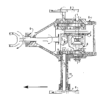
Description:
When the vehicle is equipped with a differential sun gear, it is preferrable
to
install the double axles combination inside the Gears' housing (9), as
described
herewith.
The first axle named the Back-up axle (1) is the substitute axle which
replaces the
single axle's system. Energy will be provided to this axle thru the combine
action of
the Pinion drive gear (3) to the Ring gear (4) fixed on the Differential case
{8). Said
case is supported at both ends by Bearing (7) clamped in place on the Housing
(9).
This back-up ;aide is divided into two sections the right ride and the left
axle. They
are independent from one to the other, they can run jointly at the same speed,
or at
a different sp eed, in relative rotation from one to another, but the sum of
their
rotation rates is constant, on account of the differential's Sun gear (10).
Each shaft
will rest at one end on the bevel gear of the differential while the other end
will be
installed on a Bearing (7) supported by the exterior wall of Gears' housing
(9) where
they will end. Contrary to the frontward direction for the usual single axle
driving
shaft, the back-up axle will rotate in the opposite direction, that is in a
backward
direction of tb~e vehicle.
The second axle is the Wheels's drive axle {2) that provides locomotion for
the
rear wheels of the vehicle. This driveshaft is also subdivided in two
sections: the
right wheel sb~aft and the left wheel shaft. Each section will be secured to
Housing
(9) by means of two removeable Bearings (7) clamped in place; one installed in
the
interior, the ether on the outside wall of said housing or at the end of
Shaft's
housing {11).
These two double sections axles are joined together in pairs of right and left
axles, by means of Tranfer gear (5) which are here located in between
supporting
bearings passing thru and secured to each section of axle and facing one
another, in
CA 02227433 1998-03-19
2/3
order that each impulse given to one's axle is transferred to the other axel
in a
reversed direc;tion. Since the Back-up axle is turning in a backward direction
the
wheels drive shaft will therefore run in a forward direction.
These two a:cles are integrated and interrelated so as to perform jointly and
independently. The N~ 1 Back up axle provides power to N~ 2 axle, which in
turn
transmit the wheels' generated action back to the differential of N~ 1 axle.
Both axles
performing to;;ether and acting as one single axle driving shaft.
How the invention operates
To illustrate the way the two axles drive system Fig. 2 solves the problems
inherent to sl:andard one axle drive system Fig. 1, we will compare how the
two
systems operate as shown in schematic drawings Fig. 1 and Fig. 2 (back wheels
section of a four wheels drive vehicle) .
For comparai;~on purpose, in both schemas it is assumed that the driveshaft of
the
vehicle with i1a pinion drive (3} which sets the Wheels (6) in motion are
turning in
the same direction, that is in a clockwise rotation.
When the vehicle is running the Ring gear, the Differential case, the axles
and the
wheels are synchronized to turn simultaneously in the same direction.
In the standard method of one axle vehicule as shown in Fig. 1, the Ring gear
(4) in
order to direct the Wheels (6) forward, has to be placed on the left side of
the pinion
or of the vehicle. In this way the ring gear is turning in a downward
direction. If the
ring gear blocks in place while the pinion drive is still in motion said
pinion will roll
by itself upward around the ring gear as shown in dotted line in drawing Fig.
1.
This fact is the source of the problem causing the upward lift of the front
part of a
standard vehi<;le. It can cause very serious accidents such as a complete
overturning
of pinion drive gear that can carry the vehicle all the way around towards the
back,
even to land i:n an upside down position, if the clutch is not disengaged in
time.
Such accidents can be prevented with a dual axle drive system as shown here
in Fig. 2, and Fig. 3. Power is transmitted to the vehicle thru means of two
axles.
The first axle is the Back up axle (1) which is set in motion by the Pinion
drive (3).
and Ring gear {4) thru the Differential case (8) as here indicated in the
present
schema. Sine: the Back up axle does not contain the wheels, it can be set to
turn in
a back up direction, which means that the ring gear has to rurn in an upward
direction that is from a down to up position. To achieve this goal the Ring
gear (4)
has to be located on the right side the vehicle and of the Pinion drive (3).
See
section thrue :Ring gear and Pinion Fig. 2.
Power i.s then transferred from the back up axle to the Wheels' drive axle,
which contains the wheels, by means of round Transfer gears (5) installed one
on
each section of axle, that converts the back up direction of first axle to a
forward
drive on the second axle.
Thru said combination of directional axles, if for some reason said Ring gear
blocks in plaa~ while Pinion is still in motion, said Pinion will travel
downward along
Ring gear, carrying and pressing the vehicle toward the ground which is the
goal and
achievement of present invention and prevents the capsize of vehicle.
CA 02227433 1998-03-19
3/3
Optional aura~ngement for twin axles and transfer gear
The sarne results as described in the above mentionned operations can be
obtained thru the arrangement of an integrated self contained Twin axle box
(12)
placed outside: on each side of the differential Housing (9) as shown in Fig.4
- Fig. 5
and Fig. 6. Or otherwise located at the end of the wheel's housing.
Said Twin axlE;s box (12) contains the following parts:
- The Backup axle (1) and the Wheels' axle (2) equipped with permanent
Transfer gear (14) one on each axle.
- One end of each axle rests inside the two Box's cover (15) on Rollers'
bearing
{ 16} while the N~ 1 axle extends into the differential gears { 10) while the
N~ 2
axel extends outside the box to support the wheels.
- The Box's body (13) is the implement supporting the twin axles and both
Cover' plate { 15). Said parts are held together by means of a serie of bolts
and h~~les (17) thru Body (13) and Cover plate {17).
- Each cover plate has an outgrowing profile which contains the Rollers'
Bearing
( 16). 'This knob on the cover plate is duplicated in a similar profile on the
differential housing, so that both contour's profile fit tightly together
allowing
said bo:c to hold firmly to said differential housing and secured in place by
means of Bolts (17} passing thry Plates' cover (15) and screwed to
Housing; (9}.
- Fig. 4 -- Shows the complete Twin axle box ( 12), secured to differential's
housing.
- Fig. 5 - Shows the Cover's plate 15 with Holes for bolts {17} and with the
knob's profile containing the Roller bearing. Optional oil access ( 18}.
- Fig. 6 - Shows the axle 1 and 2 integrated with Transfer gear ( 14}
contained
within Fsox's body (13).
Four wheels' dlrive
In case of four wheels driving power as illustrates in Fig. 1 and Fig. 2, the
driveshaft and the pinion of the front wheels are in both case turning
clockwise.
That means that in order to travel forward the ring gear has to turn upward
and said
ring gear has to be installed on the left side of vehicle contrary to the back
wheels'
ring gear. This is the way that the front wheels drive is already installed on
the
present vehicles, and for the front wheels the tendancy is to have a downward
thrust
when front wheels or ring gear is blocked. So there is no need to change
anything
since the dual axle arrangement is not required. Outside of reduced danger for
the
vehicle's capsize and reduced insurances fees, the newly equipped vehicle with
twin
axle combination should allow to obtain other advantages in driving
performances
such as the possibility to climb steeper hills and pull heavier loads than the
standard
vehicle and with less danger.
If in sorne instances the vehicle is blocked into a hole, by placing the gears
in a
back up drive said vehicle shoud receive an upward boost from the back and the
front wheels which should help to disengage the vehicle.