Note: Descriptions are shown in the official language in which they were submitted.
CA 02227496 1998-02-19
~RAKI~ FOR SELF-PROPELLED VEHICLE
Backclround of the Invention
l-ield of the Invention
The present invention relates to brakes and, more particularly, to parking brakes for
self-propelled, walk-behind vehicles. A preferred embodiment of the present invention
relates to a brake incorporated with a main speed control lever in a self-propelled, walk-
behind lawn mower having a hydrostatic transmission.
10 I)escription of Related Art
It is known to utilize a single stick system for controlling the maximum forward speed
of left and right drive wheels simultaneously or a two-stick system for controlling the
rnaximum forward speed of each driven wheel in a walk-behind mower, while separate hand
levers are used to make adjustments to individual drive wheel speed in a range from the
15 rnaximum speed set by the stick corresponding to each drive wheel through neutral to
reverse.
It is also known to provide a parking brake in order to prevent unintended movement
of a vehicle; however, in conventional self-propelled vehicles, a parking brake lever
20 represents an additional control which must be manipulated by an operator when stopping
and starting the mower.
In addition, many conventional walk-behind lawn mowers utilize a hydraulic system
for transmitting power from the vehicle's engine to the mower's drive wheels. These
25 systems generally include left and right drive wheels, each driven by a hydraulic motor. The
rotational speed of left and right drive wheels are commonly controlled individually by levers
actuated by an operator. These mowers are typically capable of a "zero turn radius" wherein
either the left or right drive wheel is driven forward while the other is driven in reverse.
Due to manufacturing tolerances and changes in operating conditions, the neutralposition at the operator control and the true neutral position of the hydraulic components do
not coincide, resulting in a condition where the machine will creep and possibly move out of
c:ontrol. Some machines equipped with a parking brake do not require the drive control to be
at or near neutral when applied, causing possible wear and overheating of hydraulic
35 c:omponents.
It is therefore an object of the present invention to provide a brake feature for a main
CA 02227496 1998-02-19
speed control lever in a self-propelled vehicle, which is applied simultaneously when the
c:ontrol is placed into a neutral (stop) position. It is a further object of the present invention to
extend the life of components in a hydrostatically driven vehicle by providing a brake which
i's engaged only when the vehicle's transmission is in a neutral or near-neutral position.
Summary of the Invention
The present invention provides a brake for a self propelled, walk behind vehicle, said
brake engageable by a speed control lever for regulating maximum forward speed of the
vehicle's drive wheels. Placement of the speed control lever in a stop position causes
brakes to be applied at the vehicle's drive wheels, while the vehicle's transmission is placed
in a neutral or near-neutral position. The speed control lever may also be connected to
engine ignition by means of operator presence controls which stop the vehicle's engine if an
operator leaves the operator station without placing the main speed control lever into its
neutral and braked position.
An advantage of incorporating a brake into a speed control lever is the ease andspeed with which the brake may be applied when the engine is running. For instance, if an
operator needs to remove an object from the path of the mower, the operator can stop the
rnovement of the machine without shutting down the engine.
Brief Description of the Drawin~s
FIG. 1 is a perspective view of a self-propelled, walk-behind lawn mower according to
tlhe preferred embodiment of the present invention.
FIG. 2 is a perspective view of a wheel motor control mechanism according to thepresent invention.
FIG. 3 is an enlarged view of the arrangement of left and right adjustment plates of
F igure 2.
FIG. 4 is a left-hand elevational view of a control mechanism according to the present
invention with a main speed control lever in its full-ahead position.
FIG. 5 is a left-hand elevational view of the control mechanism shown in Figure 4
CA 02227496 1998-02-19
with the main speed con,trol lev~r in its stop position.
FIG. 6 is a perspective view of a right-hand portion of a control mechanism according
to the present invention.
FIG. 7 is a perspective view of a left-hand portion of a control mechanism according
5 to the present invention
FIG. 8 is similar to Figure 7 with the elements arranged generally as they wouldappear with the main speed control placed in its stop position.
FIG. 9 is a schematic diagram of the mower drive system in a preferred embodiment
of the present invention.
Description of Preferred Embodiment
Referring now to FIG.1, there is shown a simplified perspective view of a self-
15 propelled, walk-behind lawn mower according to a preferred embodiment of the present
invention. The lawn mower generally includes left and right drive wheels 48, 50, a pair of
front wheels 51, an internal combustion engine 52 mounted on a power deck 53 which
accommodates a pair of hydrostatic transmissions, a second deck 71 which houses one or
rnore blades, and an instrument console 69 which extends between rearwardly projecting
20 handlebars 58.
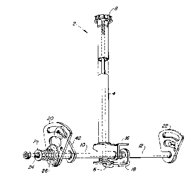
As shown in FIG.2, a wheel motor control mechanism 2 consists of a main speed
c:ontrol lever 4 formed as a hollow cylinder through which a threaded j-bolt 6 is inserted for
engagement at its threaded end with a tracking adjustment knob 8. The main speed control
25 lever 4 is welded to a left control tube 10, and is operably connected to a right control tube
12 via the rearwardly extending base of the j-bolt 6 and a control tube biasing spring 14.
1~he left and right control tubes 10,12 have left and right control tube adjustment plates 16,
18 secured to their inner ends, and terminate at left and right control rod guides 20,22 at
their outer ends. A pivot rod 24 extends through the left and right control tubes 10, 12 along
30 aln axis of rotation of the left and right control tubes 10,12. Unintended rotational movement
of the left and right control tubes 10,12 is discouraged by friction washers 26, one of which
is sandwiched between an instrument console support 68 and the left control rod guide 20
alnd the other of which is sandwiched between the instrument console support 68 and the
right control rod guide 22. A pivot rod spring 28 aids in compression of the friction washers
CA 02227496 l998-02-l9
.76.
The left and right control tube adjustment plates 16,18 are generally flat surfaces
which are biased apart by the control tube biasing spring 14. Tightening or loosening of the
tracking adjustment knob 8 effects rotation of the right control tube 12 with respect to the left
control tube 10 and increases or decreases the speed of the right drive wheel 50 with
respect to the left drive wheel 48 (Although the particular device illustrated comprises left
and right drive wheels 48,50, it is to be noted that the invention contemplates not only the
use of drive wheels, but also other ground engaging traction devices, such as tracks).
When the main speed control lever 4is manipulated by an operator, the left and right
control tubes 10, 12 change the range of movement of corresponding left and right controi
rods 34,36. The left and right control rods 34,35 are utilized to influence left and right
swashplate adjustment assemblies 38,40 (shown in FlGs. 6,7) to change the displacement
of corresponding hydraulic pumps within the transmissions. Displacement of the hydraulic
pumps relates directly to output of corresponding hydraulic motors which vary the speed of
the left and right drive wheels 48,50 from a top speed when the main speed control lever 4
is pushed forward into its full-ahead position to an approximately neutral position when the
rnain speed control lever 4is pulled back into its stop position (as shown in FIG. 5).
Referring now to Figure 8, as the main speed control lever 4is moved to its stop position, a
brake arm 42 welded to the left control tube 10 lifts a brake rod assembly 44, rotatably
rnounted to the instrument console support 68 such that the brake rod assembly 44 rotates
about a generally horizontal axis. The brake rod assembly 44 pulls a brake cable 46 to
actuate a brake engagement assembly 47. In the preferred embodiment shown, the brakes
activated by the brake engagement assembly 47 are a pair of wet brakes 72 of known
design within the hydrostatic transmissions, as shown schematically in FIG. 9, which are
used to stop rotation of the left and right drive wheels 48,50. Although the brakes 72 utilized
in the preferred embodiment of the present invention are internal wet disk brakes, use of
other types of brakes known in the art (e.g., external, shoe, disk, block, band, and cone
t)rakes)is contemplated by the invention.
During normal mowing operations, power is transmitted from an engine 52 to the left
and right drive wheels 48,50 by a pair of hydrostatic transmissions which are mounted
under the power deck 53. As shown in Figure 9 in schematic form, each hydrostatic
CA 02227496 1998-02-19
transmission comprises a system of hydraulic components including a hydraulic pump and a
hydraulic motor. The engine 52 drives the pair of hydraulic pumps, each of which is coupled
to one of the hydraulic motors for driving a corresponding one of the drive wheels 48, 50.
1~he brakes are connected to each of the left and right drive wheels 48, 50. The engine 52
5 also drives a power transfer shaft (not shown) to which one or more blades are coupled for
cutting vegetation.
Left and right steering levers 54, 56 are provided on handlebars 58. The left and
right steering levers 54, 56 are biased toward a downward position (shown in FIG. 1) due to
10 the swashplate biasing springs 39 which are connected at one end to the left or right
swashplate adjustment assembly 38, 40 and at another end to spring retainer means 41
rnounted to the power deck 53 as seen in FIGS. 6, 7. The left and right steering levers 54,
'i6 act on connecting links 37 which move corresponding left and right control rods 34, 36
along a path dictated by the left and right control rod guides 20, 22 to control the hydraulic
15 pumps in an infinite number of increments in a range from the maximum forward speed set
by the main speed control lever 4 through neutral to reverse. When the left and right
steering levers 54, 56 are in their downward biased position, the left and right drive wheels
48, 50 are propelled in a generally clockwise direction as viewed in Figure 1 at a rate
c:orresponding to the maximum forward speed set by the main speed control lever 4.
As the left and right steering levers 54, 56 are forced upward toward a neutral
position (shown in FIG. 5) by the operator, the corresponding left and right drive wheels 48,
50 are slowed. A manually engageable neutral latch 57 is provided as a control to allow the
operator to lock the pair of hydraulic pumps in an approximately neutral position, even where
25 tlhe main speed control lever 4 is in a position other than its stop position. Upward
rnovement of the left or right steering lever 54, 56 beyond the neutral position shifts a
c:orresponding one of the pair of hydraulic pumps into reverse, causing a corresponding one
of the left and right drive wheel 48, 50 to rotate opposite its direction of forward rotation.
Movement of the left steering lever 54, or the right steering lever 56 individually with
respect to the other represents a left turn or a right turn of the vehicle. In contrast,
nnovement of the main speed control lever 4 or of both left and right steering levers 54, 56 at
the same rate effects similar movement of both left and right control rods 34, 36 together and
nepresents straight-line acceleration or deceleration. However, the main speed control lever
CA 02227496 1998-02-19
4 is preferably configured such that the operator is unable to shift the pair of hydraulic pumps
into reverse by using the main speed control lever 4, and manipulation of the left and right
steering levers 54, 56 is necessary to drive the mower in reverse. In the preferred
embodiment movement of the main speed control lever 4 is limited at its stop position by the
5 top of a lever slot 72 in the instrument console 69. Although some overtravel of the main
speed control lever 4 may occur, the full ahead position of the main speed control lever 4 is
reached when a swashplate in one of the transmissions to which the main speed control
lever 4 is coupled reaches a maximum angle. The full-ahead position of the main speed
c:ontrol lever 4 may be governed by a stop, if so desired.
Other features incorporated into the preferred embodiment include left and rightoperator presence indicator levers 60, 62, which are located on the handlebars 58 opposite
the left and right steering levers 54, 56 so that they may be conveniently engaged by the
operator during operation of the vehicle. In addition, an interlock circuit is provided which is
15 c:omprised of a brake interlock switch 66 (shown in FlGs 7, 8) activated by placement of the
rnain speed control lever 4 in its stop position, and an operator presence interlock switch 67
(shown in FlGs 4, 5) activated by engagement of one of the left and right operator presence
indicator levers 60, 62. The interlock circuit allows the operator to stop the mower by placing
the main speed control lever 4 in its stop position (thereby placing the transmissions in
20 neutral and engaging the brake) and, after disengaging the blade or blades, to release the
left and right operator presence indicator levers 60, 62 and step away from the mower while
the engine 52 is running. The interlock circuit thereby allows an operator, for example, to
stop the mower and walk around it to remove an obstacle from the path of the mower, while
ensuring that the engine 52 will not run while the blade or blades are engaged and neither of
25 the left and right operator presence indicator levers 60, 62 are employed.
Also included in the preferred embodiment is an adjustable speed control stop 64which is removably secured by fastening means 65 to one of the left and right control rod
guides 20, 22 to restrict movement of the one of the control rod guides 20, 22 (and therefore
30 rnovement of the left and right control rods 34, 36 due to manipulation of main speed control
lever 4) by abutting the instrument console support 68 and preventing further movement of
tlhe left and right control rod guides 20, 22 when the left or right control rod guide 20 or 22, to
which the adjustable speed control stop 64 is secured, reaches a desired setting. The
adjustable speed control stop 64 may be set in a variety of positions, allowing the operator to
CA 02227496 1998-02-19
preset a preferred speed of operation to which he may easily return after stopping, or to lock
the main speed control lever 4 in its stop position to insure against unintendedclisengagement of the wet brakes. Setting the adjustable speed control stop 64 to lock the
rnain speed control lever 4 in its stop position is especially useful to prevent disengagement
5 of the brakes during transport as the mower may be jostled while being moved on a trailer or
other means of conveyance.