Note: Descriptions are shown in the official language in which they were submitted.
CA 02227741 2006-02-27
A UNIVERSAL PORTABLE BORING MACHINE FOR PERFORMING
BORING WORKS AND WELDING DISTRIBUTION IN AUTOMATIC AND
SEMI-AUTOMATIC, OUTSIDE AND INSIDE BLIND AND PASSING HOLES
The present invention concerns a boring machine for performing the
boring of holes, the surfacing of weldings in the holes, the lateral
levelling,
siger slots and boring by means of locoidal points, in automatic or semi-
automatic with one single placement.
It is already well known that the existing boring machines are rather
heavy and therefore can not be moved, and therefore the pieces to be
repaired must be disassembled and brought to specialised centres, with
consequent heavy time and money losses.
For what concerns electric boring machines, these with continues wire
show the inconvenience that they involve the twist of the flexible tubular
structure when the surfacing of the material must be performed for particular
parts of the piece, e.g. inside cavities or similar, that request the rotation
of
the working portion of one or more complete revolutions. For avoiding such
twist, which is particularly problematic when welding surfacings onto
cylindrical surfaces is being performed, it becomes necessary to subject the
piece to be treated to a continuous rotation which of course requires complex
operations and special technical means, due to the different of shape and
dimension of the different pieces and to the different placement of the parts
to
be treated.
An example of such a device has been described in European Patent
No. 0088305, in which the use of a fix body, rigidly carried by the flexible
tubular structure and operatively jointed with a rotating body, consisting of
the
same working part of the torch. In the bodies - fix and rotating - one or more
canalisations are provided which have the function of a guide for the
continuous wire and of feeding of the protective gas.
Appropriate creeping contacts provide for the necessary electric
continuity between one connection conductor provided in the flexible tubular
structure, and the working part of the torch, for leading tension to the
welding
wire.
However, it must be underlined that above described devices allow the
sole performance of weldings in automatic, and disadvantageously request
CA 02227741 2006-02-27
-2-
the replacing of the conventional welding torch with a new torch with a
working part rotatingly unlinked from the flexible tubular structure.
Another example is disclosed in European Patent No. EP 0100465. It
can be seen that the machine disclosed in this document is used far restoring
surfaces of blind or through holes in metallic work pieces. It has some
similarities of the machine of the present invention, in particular a tubular
box
in which three hollow shafts are arranged coaxially and inside each *other,
and
separated from one another by interposition of a pair of roller bearings with
the
hollow tool carrying shaft that supports a boring tool or a welding torch
inserted through the internal hollow shaft, an electric motor located above
the
tubular box to perform movement of rotation and a longitudinal translation.
However present invention clearly distinguishes from the machine of
the prior art. The machine disclosed in EP 0100465 has a tool carrying shaft
of limited length, and in a turning or grinding operation of through holes the
tool carrying shaft works always in a cantilevered way. The gear 33 must
slide with friction on the teeth 34 of the elongated internal gear 35, when
the
tool carrying head is longitudinally translated. A hydraulic motor or an
electric
motor supplies energy for the longitudinal translation, but also for
overcoming
friction forces, because between the teeth of the gear 33 and -the teeth 34 of
the elongated internal gear 35 a force is applied for grinding, turning or
boring
metal work pieces. No release means is provided to avoid risk of breaking the
welding torch. The motor for rotation of the tool carrying head or welding
torch is the same, and no low speed motor 5 provided. Mounting and
demounting of the main shaft is complicated because several operations have
to be done for screwing and unscrewing of several screws and fasteners.
The electric motor has no electronic control. No means for avoiding twisting
of the hose connecting welding torch to the welder is provided during helical
welding of holes. No centring device is provided for centring and aligning the
axis of the machine with the axis of the hole to repair. The machine at the
end of the run continuous to rotate and has to be brought back manually with
the risk of breaking the tools or welding torch.
The objective of the present invention is to provide an improved
CA 02227741 2006-02-27
-3-
machine, in which the external hollow shaft is free to translate
longitudinally.
Also, in the inventive machine the tool carrying shaft that supports the
boring
tool or the welding torch emerges freely from both ends of the tubular box and
therefore is of a length considerably longer than the length of the tubular
box.
In this way, two centring devices can support the tool carrying shaft. The
tool
carrying shaft is perforated with holes perpendicular to the axis of the shaft
for
insertion of a carrying tool head. The tool carrying head has a projecting key
along its length, which couples with a hollow key and a tubular hub located
inside the front end of the tubular box. A gear is mounted on the external
surface of the tubular hub and is put in rotation alternatively by one of two
electrical motors, one of which has a ball and a spring clutch. The clutch
allows automatic release of the motion for avoiding a risk of breaking of the
welding torch. The electric motor which has the clutch is a very low. speed
motor. The gear of the tubular hub and the gear of the electric motors do not
slide over each other, so that no friction arises between them. In the
inventive
machine a longitudinal translation of the external hollow shaft is determined
by an electric ratio motor, by means of a kinematic group of rotation which
includes gears that mesh with a rack rod fixed on the external hollow shaft.
The electric ratio motor must overcome the force to move longitudinally with
three hollow shafts and the tool carrying shaft. On the front of the internal
hollow shaft, a dorsal truncated cone-shaped expansion matches with a
truncated cone shaped depression located on the front of the intermediate
hollow shaft. The internal hollow shaft is subjected to the action of a
manually
operated pulling device composed of two screws. It is therefore possible, by
operating of such a device to lock the tool carrying shaft by means of the
truncated cone-shaped depression at the front end of the intermediate hollow
shaft against the truncated cone-shaped expansion at the end of the internal
hollow shaft. The expansion, due to elastic deformation of the material aided
areas which are perforated or are thinner, presses against the tool carrying
shaft. The tool carrying shaft is blocked or released only by means of
unscrewing or screwing al the two screws.
EP 0100465 does not disclose these features of the present invention.
CA 02227741 2006-02-27
-4-
In accordance with another feature of present invention, the electric motors
are controlled by electronic potentiometers to vary the revolution speed and
by an electronic inverter to reverse the longitudinal moving sense. These
features are not disclosed in EP 0100465 as well.
In accordance with the present invention, the welding torch is
connected to a continuous wire welder by a head of a coupling screwed to a
body freely rotating on a fixed body, that in turn is screwed by a threaded
ring
onto a coupling of the welder, and a continuous hole is aligned with the
components for passage of a continuous wire and for supply of a protective
gas. This solution prevents twisting of the holes connecting welding torch to
welder during helical welding of holes. These features are also not disclosed
in EP0100465.
In accordance with still a further feature of the present invention, the
front end of the tubular box presents a freely turning ring nut with internal
threaded to receiving a centring device which includes a flange screwed to the
ring nut. The flange, by means of the bolts, arms and spacers, is connected
to basis welded to the wall face of the work piece that has the hole to be
repaired. On the opposite wall face, a second centring device similar to the
first one is applied. The ring nut of the second centring device is mounted
free to rotate on a bush that is free to rotate by means of a coupling, of
ball
bearings on an internal bush that receives the perforated shaft. A pin is
inserted on the perforated shaft. The perforated shaft is manually rotated,
arms are manually moved until pin schemes during rotation, an internal
surface of the hole to be repaired, and subsequently bolts are .tied to fix
arms
and spacers. These features are also not disclosed in EP 0100465.
Furthermore, in accordance with the present invention the centring device
receives a small arm connected by a tie rod to another small arm connected
to the tool carrying head to perform automatic forward operation of levelling
plane surfaces using only the motor for the rotation movement. After the
levelling operation has been completed, the return of the tool into the
starting
position may be performed manually, by means of a screw placed on the body
of the tool carrying head, or an automatic inverting the rotation of the shaft
by
CA 02227741 2006-02-27
-5-
means of an electronic inverter. These features are also not disclosed in EP
0100465.
Finally, in accordance with the present invention the end of the total run
of the mechanism, in one sense or in the other is limited by two electronic
run
ends fixed at the rear end of the tubular box of the boring machine and by a
mechanical anti jamming clutch. Therefore, the end of the run, the machine
can not continue to rotate and does not have to be brought back manually
with risk of breaking the tools or the welding torch. These features are not
disclosed in EP 0100465 as well.
Accordingly, the present invention provides a universal portable
automatic boring and welding machine for performing boring and welding
distribution inside and outside blind and through holes, comprising a tubular
box; three nested hollow shafts arranged in said tubular box and located
coaxially, said nested hollow shaft including a first internal hollow shafts,
a
second intermediate hollow shaft which surrounds said internal hollow shaft,
and a third external hollow shaft; a pair of roller bearings separating said
hollow shafts from each other; a hollow tool carrying shaft with means for
supporting one of a boring tool, a tool carrying head and a welding torch and
inserted through said first internal hollow shaft; a plurality of electric
motors
located above said tubular box; said third external hollow shaft being free to
translate longitudinally, said tool carrying shaft emerging freely from both
ends
of said tubular box and having a length longer than a length of said tubular
box, said tool carrying shaft being formed with holes and having a projecting
key along a length which is coupled with a hollow key in a tubular hub located
inside a front end of said tubular box; a gear mounted outside said tubular
hub
and rotatable alternatingly by one of said electric motors, said one electric
motor having a ball and a spring clutch which allows automatic release of a
motion; said one electric motor which has said clutch being a low speed
motor, said electric motors including an electric ratio motor with a kinematic
group of rotation provider which effect a longitudinal translation of said
third
external hollow shaft and including a gear which meshes with a rack rod fixed
to said third external hollow shaft; a dorsal truncated cone-shaped expanded
CA 02227741 2006-02-27
-6-
section provided on front of said first internal hollow shaft and
corresponding
to a truncated cone-shaped depression provided on a front of said second
intermediate hollow shaft; a manually operated pulling device which subjects
said first internal hollow shaft to an action and is operative for locking
said tool
carrying shaft by said truncated cone-shaped depression at the front end of
said second intermediate hollow shaft against said truncated cone-shaped
expanded section at an end of said first internal hollow shaft, and said
expanded section due to elastic deformation presses against said tool
carrying shaft.
The advantages of the device according to the present invention have
already been described.
The present invention will be described more in detail here in below
relating to the enclosed drawings in which some embodiments are shown.
Figure 1 shows a vertical section of the engine group of a universal
portable boring machine for performing welding works and welding distribution
in automatic, inside and-outside blind and passing holes.
Figure 2 shows the installation of the device according to the present
invention, as a boring machine, with details shown in figure 3.
Figure 4 shows the installation of the device according to the present
invention as a welding distribution.
Figure 5 shows the constitutive details of the welder.
Figure 6 shows, in an interrupted section and in exploded view, a
variant of the device according to the present invention concerning the
assembling of a torch for the continuous wire welding surfacing.
Figure 7 shows an enlarged section for illustrating, in greater detail, the
realising details of the rotating device shown in figure 6.
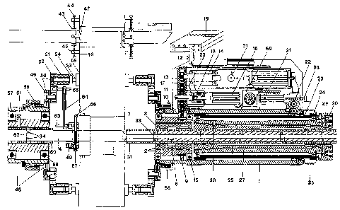
The enclosed figure show a universal portable boring machine, for
performing boring works and welding distribution in automatic, outside and
inside blind and passing holes of various diameters, with the passage of the
tool carrying shaft inside the machine with unlimited working run comprising:
a tubular box 1, inside which and at one terminal the motor hub 2 is
mounted, that allows the rotation of the carrying perforated shaft 3 and that
in
CA 02227741 2006-02-27
-7-
turn allows the rotation onto the head carrying tool shaft 4 and the rotation
of
the torch 5 for the welding-surfacing;
a hollow key 6, a piece of which projects from said motor hub 2 so as
to determine the rotation of the carrying perforated shaft 3 by means of the
key with full shaft 7, obtained onto the perforated carrying shaft 3 and with
an
0-ring 8 for allowing the cleaning of the shaft during the longitudinal
sliding in
advancing phase inside the motor hub 2 and the tubular box 1;
a gear 9 mounted outside said motor hub 2, provided with a stop with a
key 10, for the connection with the intermediate 11 for the connection with
the
gear 12, mounted with a key 13 onto the motor shaft 14 so that, when said
electric motor 14 is operated, said hub 2 rotates with the terminal bearing
15;
an electric motor 16, installed onto the distribution box 17, between the
motor 14 and the box 1, provided with a mechanic revolution reducer and a
ball and spring clutch 18, operated by a switch, and a revolution varying
device, housed onto the central 19 and connected, by means of an
appropriate lever 20 in the welding surfacing phase, with a clutch group 18
realised in such a way as to allow, during the working of the welding
surfacing, the sliding of the traction should the torch get blocked, by
avoiding
eventual breaking of the same;
a rotating mechanism mounted inside the back part of said box 1, that
allows at the same time the longitudinal moving of the perforated carrying
shaft 3 for performing the rotation of the motor hub 2, by means of the
electric
motor 14 and the connection of the gear 9 onto gear 11, 12, by means of the
electric motor 21, with the gears 22 placed onto the rack rod 23, fixed onto
the
guide element 24 of the external hollow shaft 26, and the rotation of the
internal hollow shaft 25 together with the carrying perforated shaft 3 with
the
bearings 83;
a dorsal truncated cone-shaped expansion 84 provided on a front of
said internal hollow shaft 25 and corresponding to a truncated cone shaped
depression 85 provided on a front of an intermediate hollow shaft 27; a
manually operated pulling device which subjects said internal hollow shaft 25
to an action, said manually operated pulling device having two screws 29, 30,
CA 02227741 2006-02-27
-8-
so that said tool carrying shaft is lockable by said truncated cone-shaped
depression at the front end of the intermediate hollow shaft 27 against said
truncated cone shaped expansion at an end of said internal hollow shaft 25,
said expansion 84 due to elastic deformation of a material pressing against
said tool carrying shaft 3, the intermediate hollow shaft 27 is provided, in
its
front part, with a cylindrical part onto which a stop pin 28, anti-twist with
element 25, is mounted during the advancement rotation.
For what concern the functionality of the device according to the
present invention in its possible variants, it is possible to perform:
the perforated shaft 3 carrying the torch 5 of the continuous wire welder
38 is operated by electric motors 16, 21, after having blocked the perforated
carrying shaft 3 by means of screws 29, 30, putting the ball grip of the
change
gear 31 of the electric motor 14 in neutral and operating the small lever 20
of
the electric motor 16, and operating at the same time the electric motor 16,
21;
the welding torch 5 is connected to said continuous wire welder 38 by a
head 76 of a coupling 75 screwed to a body 39 freely rotated on a fixed body
35 which is screwed by a threaded ring 39 onto a coupling of the welder, a
continuous hole 40 being aligned for passage of a continuous wire 73 and for
supply of protective gas;
the boring of the parts surfaced by welding putting the electric motor 16
of the welder in neutral by means of the small lever 20 and inserting the
desired gear by means of the ball-grip of the change gear 31 of the electric
motor 14, taking off the torch and inserting into the same housing the head-
carrying tool shaft 4 and, by means of the insertion of a cylindrical pin into
one
of the existing holes 33 of the head carrying tool shaft and on the hole
existing
on the perforated carrying shaft 3, blocking said pin by means of two
sheathings threaded onto holes existing onto the head carrying tool shaft.
In the variant shown in figures 6 and 7, the device for the rotating
connection of a torch to a continuous wire welder, comprises a fix body 35
having a head 36 for the connection to the conventional connection sleeve 37
provided in welder 38, and a connection sleeve that may be engaged by the
CA 02227741 2006-02-27
-9-
terminal head connected to a conventional welding torch. The fix and rotating
bodies 39 are crossed by a first hole 40 and by a second longitudinal channel,
through which the continuous welding wire, coming from sleeve 37 for the
connection head, that may be engaged with a respective seat provided in
connection sleeve 36, 37 for feeding protective gas into the longitudinal
channels; the electric continuity between the connection sleeve and the
terminal head of the torch provided by operating switch 41 for the ignition of
the welder, through the fix and movable bodies realised out of electrically
conductive material.
After having fixed the tool carrying head 42 onto the head carrying
shaft 4, the boring phase may be performed as well lateral and frontal
levelling. Furthermore, during boring on passing through boles it is suggested
to install a plurality of supports for the holding of the shaft on the side
opposite
to the boring machine.
For what concerns the installation of the boring machine in a position
central to the hole to be retreated, the system for centring on the working
point is in any case always the same:
on bushes 43, once the bolts 44 are screwed with the terminal 45
placed one on one side and one on the other side of the working piece, fixed
in the welding points 46, said bolts 44 are screwed into brackets 46, and
rotating the bushes 43 the auxiliary shaft 4' is inserted, said shaft being
provided with holes 33 for above mentioned centring as well as for the
hooking of said perforated carrying shaft placed inside the boring machine, so
that with a lever 81 and adjustment of said bolts 44 a position of the
auxiliary
shaft 4' is regulated before the machine is mounted;
in the hole 33 of said shaft, realised for performing said centring as well
as the hooking of said perforated carrying shaft placed inside the boring
machine 3, in the centring phase a small pin 47 is inserted so that when the
shaft is manually rotated the walls of the hole to be treated are skimmed and,
through the adjusting of the bolts 44 of the centring system, the same
centring
of above mentioned shaft 4' is obtained; onto the same shaft, and from both
sides one or more supports for the holding of the shaft 3 must be inserted
CA 02227741 2006-02-27
-10-
according to the working needs;
to realise the support, the tubular box 1 has a front end forming a
freely turning ring nut 56 with an internal threading; and further comprising
a
centring device which is received in said internal threading and has a flange
49 screwed to said ring nut 56, said flange 49 being connected to bases
welded to a wall face of a work piece which has a hole to be repaired; a
second centring device which is similar to said first mentioned centring
device
and applied on an opposite wall face, said second centring device having a
ring nut 56 which is mounted free to rotate on a bush 57 which is free to
rotate
by a couple of ball bearings 58 on an internal bush 59 which receives a
perforated shaft 3, a pin inserted on said perforated shaft 3, said perforated
shaft being manually rotated, arms 52 being manually moved until pin skims
during rotation, the internal surface of the bole to be repaired; and bolts 50
which are subsequently fixed to arms 52 and spacers 51 once said operation
has been performed, and while the support 48 remains on the shaft, the bolts
53 are adjusted onto the wall to be treated by pushing them fore or
backwards by means of the screw-thread, and blocked by the lock nuts 54 so
that, with a part of substantial welding between the head of the bolt 55 and
the
wall to be treated, said supports remain fixed onto said wall;
when said operation has been performed on both sides, the centring
system must be eliminated, taking off the shaft so that the sole supports of
the
shaft and of the boring machine remain on the wall to be treated; -
on that side, where the boring machine is to be fixed, the internal
rotating group of the support must be taken off, and in that housing the
boring
machine must be inserted so that, through the locking of the threaded ring
nut 56, the locking of said boring machine is obtained on the point to be
treated in a position centred to the hole to be re-treated; in case of blind
holes
only one support is needed for working, i.e. -the sole boring machine is used
which on its side replaces the rotating part of the internal support 57 as, in
such cases, it is impossible to use the second support in the phase of welding
surfacing and boring.
Above mentioned supports 48 with a transferable inside, are realised
CA 02227741 2006-02-27
-11-
with the shell 57 and inside the bearings 58 are inserted, and inside said
bearing a guide bush 59 is provided and inside said bush a further bush 60
which, during rotation, is out of one piece with the tool carrying shaft that
has
a bush 60 with a screw 61, and during the advancement in the working phase,
said bush 60 moves together with the head carrying tool shaft 3, in
longitudinal sense as it is provided with a small key, so that during rotation
bush 60 has the possibility of rotating together with bush 59 and of moving
longitudinally together with the shaft, as said bush 60 is fixed to the head -
carrying tool shaft by the connection with a small pin 62 and said small pin
is
fixed by means of threaded sheathing 34 so that said bush is out of one piece
with the head carrying tool shaft.
Consequently said bush 60 is realised for reinforcing the holding of the
shaft the boring working, as well as the head carrying tool shaft 3 placed
inside the boring machine.
The small arms 63, 64, 65 are used for performing the automatic
advancement of the tool carrier 66 during the levelling operation, making
siger
joints, operating only the electric motor 14 for the shaft's rotation, with
out
operating the advancement motor reducer. After having performed the first
levelling, the return of the tool into the tool carrying head may be performed
manually, by means of screw 67, placed on the body of the tool carrying head,
or inverting the rotation of the shat in automatic by means of an electronic
inverter.
For increasing the second levelling it is possible to move in centesimal
steps the special hand wheel 68, provided on the back pan of the boring
machine, connected on the electric motor 21.
The boring machine according to the present invention is cooled down
by conditioned air by means of suitable cooling fans provided on the driving-
axle. Furthermore, with the installation of an additional fan 69, at the
centre of
the boring machine, the suction of the warm air, produced by electric engines,
is obtained leading it outside the bonnet that encloses the whole mechanism
for the protection of the operator and of the mechanism.
The lubrication of all rotating elements is provided with a tight system
CA 02227741 2006-02-27
-12-
exempted of periodical checks.
The extension of the head carrying tool shaft is composable by special
adjustment male female and safety key in conical expansion.
The end of the total run of the advancement mechanism 70, in one
sense or in the other, is limited by two electronic run ends fixed backwards
to
the body 1 of the boring machine and by a mechanical anti-jamming clutch.
The advancement depth required time by time during working, in boring
as well as in welding surfacing, is programmed by the electronic control
panel,
with display. Also the rotation sense, the revolution speed and the
advancement speed and the instructions in various languages is stored on the
same central panel, and in case of need the information concerning the
performance of the working phases and of fixing of the machine can be shown
on the display.
The advancement mechanism is protected by a rubber anti oil bellows
against dust.