Language selection

Search

Patent 2227816 Summary

Third-party information liability

Some of the information on this Web page has been provided by external sources. The Government of Canada is not responsible for the accuracy, reliability or currency of the information supplied by external sources. Users wishing to rely upon this information should consult directly with the source of the information. Content provided by external sources is not subject to official languages, privacy and accessibility requirements.

Claims and Abstract availability

Any discrepancies in the text and image of the Claims and Abstract are due to differing posting times. Text of the Claims and Abstract are posted:

  • At the time the application is open to public inspection;
  • At the time of issue of the patent (grant).
(12) Patent: (11) CA 2227816
(54) English Title: FASTENING ELEMENT
(54) French Title: ELEMENT DE FIXATION
Status: Expired and beyond the Period of Reversal
Bibliographic Data
(51) International Patent Classification (IPC):
  • F16B 21/07 (2006.01)
  • B01D 35/30 (2006.01)
  • B29C 45/16 (2006.01)
  • H05K 5/02 (2006.01)
(72) Inventors :
  • RIEGER, MARIO (Germany)
(73) Owners :
  • FILTERWERK MANN & HUMMEL GMBH
(71) Applicants :
  • FILTERWERK MANN & HUMMEL GMBH (Germany)
(74) Agent: NORTON ROSE FULBRIGHT CANADA LLP/S.E.N.C.R.L., S.R.L.
(74) Associate agent:
(45) Issued: 2007-08-28
(86) PCT Filing Date: 1996-05-15
(87) Open to Public Inspection: 1997-02-06
Examination requested: 2003-05-15
Availability of licence: N/A
Dedicated to the Public: N/A
(25) Language of filing: English

Patent Cooperation Treaty (PCT): Yes
(86) PCT Filing Number: PCT/EP1996/002089
(87) International Publication Number: WO 1997003801
(85) National Entry: 1998-01-26

(30) Application Priority Data:
Application No. Country/Territory Date
195 26 934.9 (Germany) 1995-07-24

Abstracts

English Abstract


A fastening element for a plastic housing, especially a filter housing,
which is fitted to a supporting structure so as to damp vibrations. To this
end
the housing is provided with a fastening element comprising a rubber-elastic
member, especially a member produced by the two-component injection molding
method, and a mounting member of the support structure is lockingly engaged
with the fastening element so that the fastening element of the housing is
functionally connected to the supporting structure.


French Abstract

L'invention concerne un élément de fixation destiné à un boîtier en matière plastique, notamment un boîtier à filtre. Un tel boîtier est notamment monté sur une structure de fixation de façon que les vibrations soient amorties. A cet effet, une zone de fixation est prévue à l'intérieur du boîtier avec, dans cette zone, un élément ayant l'élasticité du caoutchouc (12), notamment un élément réalisé selon la technique de moulage par injection à deux composantes. Cet élément est relié de façon fonctionnelle à la structure de fixation (27).

Claims

Note: Claims are shown in the official language in which they were submitted.

6
CLAIMS:
1. A fastening element for securing a plastic housing to a support structure,
said
fastening element comprising a rubber-elastic connecting element integrally
molded
on said plastic housing by a two-component injection molding process, wherein
one
of said support structure and said rubber-elastic connecting element comprises
an
aperture and the other of said support structure and said rubber-elastic
connecting
element comprises an integral pin or plug securely received in said aperture.
2. A fastening element according to claim 1, wherein said housing is an air
filter
housing for an internal combustion engine of a motor vehicle.
3. A fastening element according to claim 1, wherein said rubber-elastic
connecting element is formed of a thermoplastic elastomer.
4. A fastening element according to claim 1, wherein the rubber-elastic
connecting element comprises a plug portion received in an aperture of the
support
structure, and said plug has a tolerance compensating body structure
comprising
radially extending compressible ribs formed exteriorly on said plug.
A fastening element according to claim 1, wherein the rubber elastic
connecting element comprises a strap member with an aperture therein for
receiving
an integral pin on the support structure; said strap member having a vibration-
damping body structure comprising at least one pleat with flexible flanks in
said strap
member between said aperture and said housing.
6. A fastening element according to claim 1, wherein the fastening element has
a
contour which can be lockingly received in an opening in the support
structure.

Description

Note: Descriptions are shown in the official language in which they were submitted.


CA 02227816 1998-01-27
FASTENING ELEMENT
DESCRIPTION
BACKGROUND OF THE INVENTION
The invention relates to a fastening element for fastening a housing,
especially a filter housing, to a supporting structure.
In the state of the art a large number of fastening elements are known.
The simplest kind is a screw fastener. This, however, has the disadvantage
that
additional elements such as a screw and a nut are necessary, and assembly
requires considerable effort.
It is also known to mount a housing on a supporting structure with a snap
fastener. To this end a pin, for example, is provided on the housing, and is
snapped into a corresponding opening in the supporting structure. A
disadvantage of this system, however, is the need for close tolerances. Also,
several working steps are required in the manufacturing process.
SUMMARY OF THE INVENTION
The object of the invention, therefore, is to provide a fastening element
which is simple and inexpensive to manufacture, and which also eliminates the
need for close manufacturing tolerances, and offers good acoustical isolation.
This object is achieved by providing a fastening element for securing a
plastic housing to a supporting structure, wherein a holding area is provided
on
the housing, and a rubber-elastic element is formed on said housing in said
holding area and is connected to the supporting structure.
The important advantage of the invention is that the fastening element is
equipped with a rubber-elastic element, which is made especially by the two-
component injection molding method. Such a fastening element can be disposed
on the plastic housing in a single procedure during the manufacture of the
latter.
No subsequent treatment or additional processing are necessary.
According to an advantageous embodiment of the invention, the rubber-
elastic element is composed of an elastomer, especially a thermoplastic
elastomer (TPE).
1

CA 02227816 1998-01-27
TPE can be worked by injection molding and has rubber-elastic
properties wliich can be adapted in their composition to a particular
application.
An additional advantageous embodiment provides for configuring the
rubber-elastic element so as to achieve great tolerance-compensating effects.
This can be accomplished, for example, in that this element had a kind of
pleated structure, or in that parts of the element are configured in the
manner of
a cradle held at both ends.
One advantageous embodiment envisions the rubber-elastic element being
provided with a vibration-damping body structure. Here again the use of TPE
has the advantage that this material has high damping qualities and
consequently
vibrations caused by the supporting structure to which it is fastened are not
transmitted to the housing, especially the filter housing. Such vibrations are
created, for example, in a motor vehicle. Especially the components of the
motor, such as the filter housing and other peripheral elements, must be
effectively decoupled from these vibrations. The fastening element is suitable
for doing this.
In order to affix the housing to the supporting structure, the fastening
element is lockingly engaged with a corresponding counterpart member. This
can be, for example, a screw or a pin. Of course, other fastening elements are
conceivable, such as straps. For fastening by means of a screw, it is
desirable to
provide in the rubber-elastic element a metal bushing which defines the
effective
screw length.
An advantageous variant of the invention provides for configuring the
fastening element with a plug-in shape in the form of a pin. This pin is
inserted
into an opening in the supporting structure. Here, too, various shapes can be
achieved which display both a tolerance compensating and a vibration damping
action.
These and other features of preferred embodiments of the invention are
to be found not only in the claims, but also in the description and the
drawings;
whereby the individual features each can be realized by themselves along or in
2

CA 02227816 1998-01-27
subcombinations in the embodiment of the invention, and can be applied to
other
fields of use and constitute advantageous as well as independently patentable
features, for which protection is here claimed.
BRIEF DESCRIPTION OF THE DRAWINGS
The invention will be further explained below with the aid of
embodiments. The drawings show:
Figure 1 a section taken through a fastening element made by a two-
component technique;
Figure 2 a sectional view of a fastening element having vibration damping
properties;
Figure 3 a sectional view of a fastening element with an extended spring
flexure for vibration damping;
Figure 4 a sectional and a top view of a fastening element having a simple
strap construction;
Figure 5 a sectional view of a simple fastening element having a spring
action for vibration damping;
Figure 6 a plug in axial and radial cross section;
Figure 7 a variant embodiment of a plug; and
Figure 8 a housing with fastening elements.
DETAILED DESCRIPTION OF PREFERRED EMBODIMENTS
The sectional view of a fastening element according to Figure 1 shows a
portion of a plastic housing 10 in which a fastening element, i.e., a rubber-
elastic element 12, is disposed in an opening 11. This element is manufactured
by the two-component injection molding process, i.e., in this process
initially
the first component, i.e., the plastic housing, is cast, and subsequently a
slide is
opened in the mold. This slide exposes the cavity for the rubber-elastic
element.
The composition for making the fastening element is injected into this cavity.
After both elements or components have cooled, the complete housing can be
removed from the injection mold.
3

CA 02227816 1998-01-27
The fastening element 12 is provided with a metal sleeve 13. Of course,
such a sleeve is necessary only when it is in working connection with a
threaded
bolt or the like.
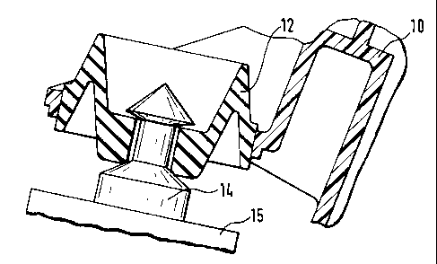
Figure 2 again shows a portion of the plastic housing 10. The fastening
element 12 is disposed thereon by the two-component injection molding
technique. It has a shape which is especially suitable for effectively damping
vibrations which are transmitted through the fastening pin 14 from the
supporting structure 15. Moreover, the design of the fastening element 12 is
suitable for compensating positional tolerances between the mounting pin 14
and
the plastic housing 10.
Figure 3 shows a sectional view of a fastening element with an extended
flexural length or softer action. Here again the plastic housing 10 can be
seen in
part. The fastening element 12 is disposed on it. This fastening element has
two long flanks 16 and 17 which, on the one hand, facilitate very great
compensation of position, and on the other hand have very good vibration
damping properties.
Figure 4 shows in cross section and in plan view a fastening element of
simple strap-like design. The fastening element 12 is injection molded on the
plastic housing 10 in the manner of a strap. The plan view shows that this
strap
has at its front end an eye which is equipped with a bore 18 to accommodate a
bolt, not shown here. The connection between the fastening element 12 and the
plastic housing can be configured in any desired manner and withstands very
large forces.
In Figure 5, a fastening element is arranged on the plastic housing 10
which is a simple strap, but also additionally has a bent fastener portion 19.
This facilitates better spring action to damp vibrations.
Figure 6 shows a plug. In the axial section it can be seen that on the
plastic housing 10 this plug is configured as a hollow cylindrical element 20.
The radial section shows the structure of the hollow cylindrical element. This
is
4

CA 02227816 1998-01-27
provided on its exterior with ribs 21. To fasten the plastic housing 10 to a
supporting structure, the element is inserted into a receiving bore.
Figure 7 shows a variant of the fastening element. While in the axial
section its integration with the plastic housing 10 can be seen, the radial
section
shows that the surface has no ribs. To secure the assembly, a cross rib 28 is
provided. This prevents assembly errors, i.e. pinching of the buffer on the
housing or on sheet metal is not possible. The cross rib assures that the
fastening element also gets into the fastening bore.
In Figure 8 the complete structure is shown. A plastic housing 10 is
provided witli a plug 23 and two fastening straps 24 and 25. By means of the
plug 23 the plastic housing is plugged into an opening 26 in the supporting
structure 27. Mounting pins are provided on the supporting structure in the
area
of the fastening straps 24 and 25. The fastening elements 12 integral with the
respective fastening straps 24 and 25 are affixed to the mounting pins.
The installation of the plastic is thereby very greatly simplified and is
performed substantially in a single operation, namely the insertion of the
housing by means of the plug and pressing it down onto the fastening pins 14.

Representative Drawing
A single figure which represents the drawing illustrating the invention.
Administrative Status

2024-08-01:As part of the Next Generation Patents (NGP) transition, the Canadian Patents Database (CPD) now contains a more detailed Event History, which replicates the Event Log of our new back-office solution.

Please note that "Inactive:" events refers to events no longer in use in our new back-office solution.

For a clearer understanding of the status of the application/patent presented on this page, the site Disclaimer , as well as the definitions for Patent , Event History , Maintenance Fee  and Payment History  should be consulted.

Event History

Description Date
Time Limit for Reversal Expired 2014-05-15
Letter Sent 2013-05-15
Grant by Issuance 2007-08-28
Inactive: Cover page published 2007-08-27
Inactive: Final fee received 2007-06-07
Pre-grant 2007-06-07
Notice of Allowance is Issued 2007-03-06
Letter Sent 2007-03-06
Notice of Allowance is Issued 2007-03-06
Inactive: Approved for allowance (AFA) 2007-02-19
Amendment Received - Voluntary Amendment 2006-12-20
Inactive: S.30(2) Rules - Examiner requisition 2006-12-06
Amendment Received - Voluntary Amendment 2006-06-20
Inactive: IPC from MCD 2006-03-12
Inactive: S.30(2) Rules - Examiner requisition 2005-12-23
Inactive: First IPC assigned 2003-07-18
Letter Sent 2003-06-12
Request for Examination Requirements Determined Compliant 2003-05-15
All Requirements for Examination Determined Compliant 2003-05-15
Amendment Received - Voluntary Amendment 2003-05-15
Request for Examination Received 2003-05-15
Inactive: Adhoc Request Documented 2002-12-05
Request for Examination Received 2002-10-24
Classification Modified 1998-05-07
Inactive: IPC assigned 1998-05-07
Inactive: First IPC assigned 1998-05-07
Inactive: IPC assigned 1998-05-07
Inactive: Notice - National entry - No RFE 1998-04-23
Application Received - PCT 1998-04-20
Amendment Received - Voluntary Amendment 1998-01-27
Amendment Received - Voluntary Amendment 1998-01-26
Application Published (Open to Public Inspection) 1997-02-06

Abandonment History

There is no abandonment history.

Maintenance Fee

The last payment was received on 2007-04-20

Note : If the full payment has not been received on or before the date indicated, a further fee may be required which may be one of the following

  • the reinstatement fee;
  • the late payment fee; or
  • additional fee to reverse deemed expiry.

Patent fees are adjusted on the 1st of January every year. The amounts above are the current amounts if received by December 31 of the current year.
Please refer to the CIPO Patent Fees web page to see all current fee amounts.

Owners on Record

Note: Records showing the ownership history in alphabetical order.

Current Owners on Record
FILTERWERK MANN & HUMMEL GMBH
Past Owners on Record
MARIO RIEGER
Past Owners that do not appear in the "Owners on Record" listing will appear in other documentation within the application.
Documents

To view selected files, please enter reCAPTCHA code :


To view images, click a link in the Document Description column. To download the documents, select one or more checkboxes in the first column and then click the "Download Selected in PDF format (Zip Archive)" or the "Download Selected as Single PDF" button.

List of published and non-published patent-specific documents on the CPD .

If you have any difficulty accessing content, you can call the Client Service Centre at 1-866-997-1936 or send them an e-mail at CIPO Client Service Centre.


Document
Description 
Date
(yyyy-mm-dd) 
Number of pages   Size of Image (KB) 
Representative drawing 1998-05-11 1 6
Description 1998-01-26 5 200
Abstract 1998-01-26 1 13
Claims 1998-01-26 2 35
Description 1998-01-25 5 178
Abstract 1998-01-25 1 52
Drawings 1998-01-25 3 68
Claims 1998-01-25 1 24
Claims 2006-06-19 1 40
Claims 2006-12-19 1 38
Abstract 2007-06-19 1 13
Representative drawing 2007-07-31 1 12
Reminder of maintenance fee due 1998-04-22 1 111
Notice of National Entry 1998-04-22 1 193
Courtesy - Certificate of registration (related document(s)) 1998-04-22 1 116
Reminder - Request for Examination 2003-01-15 1 112
Acknowledgement of Request for Examination 2003-06-11 1 173
Commissioner's Notice - Application Found Allowable 2007-03-05 1 162
Maintenance Fee Notice 2013-06-25 1 171
PCT 1998-03-25 6 188
International preliminary examination report 1998-01-25 12 419
Correspondence 2007-06-06 1 38