Language selection

Search

Patent 2228319 Summary

Third-party information liability

Some of the information on this Web page has been provided by external sources. The Government of Canada is not responsible for the accuracy, reliability or currency of the information supplied by external sources. Users wishing to rely upon this information should consult directly with the source of the information. Content provided by external sources is not subject to official languages, privacy and accessibility requirements.

Claims and Abstract availability

Any discrepancies in the text and image of the Claims and Abstract are due to differing posting times. Text of the Claims and Abstract are posted:

  • At the time the application is open to public inspection;
  • At the time of issue of the patent (grant).
(12) Patent: (11) CA 2228319
(54) English Title: OSCILLATING PISTON FLOWMETER
(54) French Title: DEBITMETRE OSCILLANT A PISTON
Status: Term Expired - Post Grant Beyond Limit
Bibliographic Data
(51) International Patent Classification (IPC):
  • G01F 1/20 (2006.01)
  • G01F 3/08 (2006.01)
(72) Inventors :
  • LANG, GERHARD (Germany)
(73) Owners :
  • M & FC HOLDING LLC
(71) Applicants :
  • M & FC HOLDING LLC (United States of America)
(74) Agent: SMART & BIGGAR LP
(74) Associate agent:
(45) Issued: 2002-06-11
(22) Filed Date: 1998-01-29
(41) Open to Public Inspection: 1999-02-01
Examination requested: 1999-12-15
Availability of licence: N/A
Dedicated to the Public: N/A
(25) Language of filing: English

Patent Cooperation Treaty (PCT): No

(30) Application Priority Data:
Application No. Country/Territory Date
297 13 705.0 (Germany) 1997-08-01

Abstracts

English Abstract


An oscillating flowmeter including a measuring chamber
having a bottom, a cylindrical jacket, a central journal, a
guide ring, a separating wall, and inlet and outlet openings,
and a piston located in the measuring chamber and having a
bottom, a cylindrical skirt, at least one pilot journal
engageable with and rotatable about the central journal of the
measuring chamber, and a guiding slot extending in the skirt
and the bottom and up to separating wall of the measuring
chamber, with at least one of the central journal of the
measuring chamber and the pilot journal of the piston being
formed as a resiliently pliable member.


French Abstract

Débitmètre oscillant comprenant un bac jaugeur ayant une partie inférieure, un manchon cylindrique, un tourillon central, un anneau de guidage, une paroi de séparation, des orifices d'entrée et de sortie, et un piston logé dans le bac jaugeur et comprenant une partie inférieure, une chemise cylindrique et au moins un tourillon pilote pouvant s'engager avec le tourillon du bac jaugeur et pouvant pivoter autour de celui-ci; au moins un des tourillons, soit le tourillon central ou le tourillon pilote du piston est formé d'un élément pliant résilient.

Claims

Note: Claims are shown in the official language in which they were submitted.

WHAT IS CLAIMED IS:
1. An oscillating flowmeter, comprising:
a measuring chamber having a bottom, a
cylindrical jacket, a central journal a guide
ring, a separating wall, and inlet and outlet
openings; and
a piston located in the measuring chamber and
having a bottom, a cylindrical skirt, a pilot
journal engageable with and rotatable about the
central journal of the measuring chamber, and a
guiding slot extending in the skirt and the bottom
and up to separating wall of the measuring
chamber,
wherein at least one of the central journal
of the measuring chamber and the pilot journal of
the piston is formed as a resiliently pliable
member.
2. An oscillating piston flowmeter as set forth in
claim 1, wherein the at least one of the central journal and
the pilot journal is formed as a thin-wall cylinder.
-10-

3. An oscillating piston flowmeter as set forth in
claim 1, wherein the at least one of the central journal and
the pilot journal is formed of a viscoplastic material.
-11-

Description

Note: Descriptions are shown in the official language in which they were submitted.


CA 022283l9 l998-0l-29
BACKGROUND OF THE lNv~NLlON
:L. Field of the Invention
The present invention relates to an oscillating piston
flowmeter including a measuring chamber having a bottom, a
cylindrical jacket, a central journal, a guide ring, a
separating wall, and inlet and outlet openings; and a piston
located in the measuring chamber and having a bottom, a
cylindrical skirt, a pilot journal engageable with and
rotatable about the central journal of the measuring chamber,
and a guiding slot extending in the skirt and the bottom and
up to separating wall of the measuring chamber.
:2. Description of the Prior Art
Oscillating piston flowmeters, which relate to
volumetric flowmeters, include a measuring chamber through
which an. entire amount of a liquid flows. At that, a portion
of the potential energy of the to-be-measured water, which
energy is used for driving the flowmeter, becomes lost. The
resultin.g pressure drop is indicated as pressure loss P. The
pressure drop is caused by a change of direction of water
flow, a change of a cross-section of the water conduit along
the path of water flow, etc.
-210455.1
12/30/97 ll:Olam -2-

CA 022283l9 l998-0l-29
There is arranged in the measuring chamber an
oscillating piston which is displaced during the measuring
process from a high pressure side to the low pressure side.
This takes place automatically under the action of the water
flow which regularly splits in the measuring chamber in a
plurality of streams. Upon rotation of the piston, two
different volumes of constant predetermined magnitudes are
conveyed. At that, the lower pilot journal of the piston
rotates about the central journal of the measuring chamber.
The piston skirt has a slot along its entire height.
Upon rotation of the piston, this slot reciprocates along the
separating wall which is provided in the measuring chamber.
The advantage of the reciprocating movement consists in that
the piston automatically returns in its initial position
without any need in additional control devices, valves,
slides, etc. Inner and outer piston guide means insure the
necessary movement of the piston. The piston is also provided
with an upper journal which drives a driver which transmits
the circular movement of the upper journal to a counter.
The measurement precision of oscillating piston
flowmeter to a large extent depends on the dimensional
accuracy of the elements of the measuring chamber. The
-210455.1
12/30/97 ll:Olam ~3-

CA 02228319 1998-01-29
smaller is the clearance between the piston and the measuring
chamber the less amount of liquid can pass unnoticed, and the
smaller is the measurement error. However, from a functional
point of view, a minimal clearance between the piston and the
measuring chamber is needed to prevent the piston from
jamming. A typical magnitude of the clearance between movable
parts is smaller of or equal to 10~m. Often, the to-be-
measured liquid contains dirt particles, e.g., rust, sand and
the like, in case of drinking water. Often different salts
precipitate from a liquid, e.g., lime in case of the drinking
water. As a rule, these foreign substances pass past the
piston without problems. However, now and then it may occur
that these particles accumulate in the functional clearance
between the piston and the wall of the measuring chamber.
When these particles are loose, they are pushed by the
piston to the measuring chamber, without causing any trouble.
At that, the movement of the piston slightly slows down,
without noticeably affecting the measurement accuracy.
l~owever, when the particles stuck in the clearance,
they can block the movement of the piston, and the flowmeter
fails.
-2104551
12/30/97 il:Olam ~4~

CA 02228319 1998-01-29
Further, there exists a possibility of the piston being
rubbed by the particles. This may result in formation of
scratches in the walls of the piston and/or the measuring
chamber, which increase the actual clearance between the
piston and the wall of the measuring chamber. This does not
result in a failure of the flow-meter, but its measurement
accuracy is reduced.
Accordingly an object of the present invention is to
provide an oscillating piston of the above-described type in
which the blocking of the piston movement is prevented and a
possibility of a damage the walls of the piston and the
measuring chamber is substantially reduced.
SUMMARY OF THE lNV~NllON
This and other objects of the present invention, which
will become apparent hereinafter, are achieved by forming at
least one of the central journal of the measuring chamber and
the piston pilot journal resiliently pliable.
'rhe present invention permits a temporary lift of the
piston of the wall of the measuring chamber, which prevents
the piston from being blocked in its movement and, in majority
-210455.1
12/30/97 ll:Olam ~5~

CA 02228319 1998-01-29
of cases, scratching of the walls of the piston and/or the
measuring chamber. Even under most unfavorable circumstances,
the measurement accuracy is affected only for a very short
period. A further advantage of the oscillating piston
flowmeter according to the present invention consists in that
its operational service life is increased. It is well known
that the central journal of the measuring chamber and the
pilot journal of the oscillating piston are subjected during
operation of the flow-meter to a substantial wear, which leads
to a non-uniform spitting of the liquid flow and to its non-
uniform discharge. Due to resilient or elastic pliability of
the journals, periodically occurring forces,which results from
a non-uniform flow, are elastically absorbed and cushioned.
In accordance with advantageous embodiment of the
present invention, the central journal and/or resilient
journal are formed as a thin-wall cylinder.
'rhe resiliently deformable or pliable journals are
advantageously formed of a viscoplastic material.
NY1-210455 . 1
12/30/97 11: Olam -6-

. CA 02228319 1998-01-29
BRIEF DESCRIPTION OF THE DRAWINGS
1'he features and objects of the present invention will
become more apparent, and the invention itself will be best
understood from the following detailed description of the
preferred embodiments when read with reference to the
accompanying drawings, wherein:
E'ig. 1 shows a plan view of a conventional oscillating
piston flowmeter with the cover of the measuring
chamber being removed; and
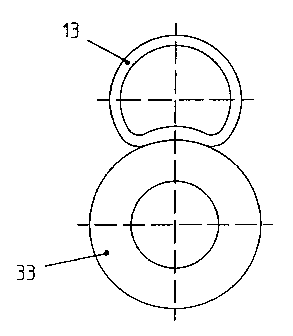
E'ig. 2 shows a cut-out view of the oscillating piston
flowmeter shown in Fig. 1 at an increased scale,
illustrating the present invention.
DETATT.T~'n DESCRIPTION OF THE PREFERRED EMBODIMENT
Fig. 1 shows a plan view of an oscillating piston
flowmeter with elements necessary for explaining the present
invention. The oscillating piston flowmeter shown in Fig. 1
has a measuring chamber 10 with a bottom 11, a cylindrical
measuring chamber jacket 12, a central journal 13, a guide
ring 14, and a radial separating wall 15. On the left from
NYl-210455 . 1
12/30/97 11: Olam -7~

CA 02228319 1998-01-29
the separating wall 15, there is a sickle-shaped inlet opening
16, and on the right from the separating wall 15, there is a
likewise sickle-shaped outlet opening 16' for the measured
water.
Inside of the measuring chamber 10, there is provided
an oscillating piston 30 having a cylindrical piston skirt 31,
a piston bottom 32 and a pilot journal 33. The pilot journal
33 moves along a circle about the central journal 13.
A radial slot 34 is formed in the piston skirt 31 and
the piston bottom 32. The slot 34 permits to pin the
oscillating piston 30 on the separating wall 15. The
rectilinear formed by the separating wall 15, and a circular
guide, which is defined by a combination of the guide ring 14
and the central journal 13, provide for the oscillating
movement of the piston 30, as is known.
When dirt particles 1 are caught in a narrow functional
clearance between the jacket 12 of the measuring chamber 10
and the piston skirt 31, they adversely affect the movement of
the oscillating piston 30 until they completely block it. To
prevent such blocking, the central journal 13 is formed
resiliently pliable. As shown in Fig. 2 at an increased
-210455.1
12~30~97 ll:Olam -8-

CA 022283l9 l998-0l-29
scale, the central journal is formed as a thin-wall cylinder
of a viscoplastic material. As a result, the central journal
can be elastically deformed, with the oscillating piston 30
evading the dirt particles when yielding laterally. The
evasion is also insured when the piston journal 33 is formed
resiliently pliable.
Though the present invention was shown and described
with references to the preferred embodiments, various
modifications thereof will be apparent to those skilled in the
art and, therefore, it is not intended that the invention be
limited to the disclosed embodiments or details thereof, and
departure can be made therefrom within the spirit and scope of
the appended claims.
-210455.1 9
12/30/97 ll:Olam

Representative Drawing
A single figure which represents the drawing illustrating the invention.
Administrative Status

2024-08-01:As part of the Next Generation Patents (NGP) transition, the Canadian Patents Database (CPD) now contains a more detailed Event History, which replicates the Event Log of our new back-office solution.

Please note that "Inactive:" events refers to events no longer in use in our new back-office solution.

For a clearer understanding of the status of the application/patent presented on this page, the site Disclaimer , as well as the definitions for Patent , Event History , Maintenance Fee  and Payment History  should be consulted.

Event History

Description Date
Inactive: Expired (new Act pat) 2018-01-29
Inactive: Late MF processed 2017-01-23
Letter Sent 2016-01-29
Inactive: IPC from MCD 2006-03-12
Letter Sent 2005-11-16
Inactive: Multiple transfers 2005-10-25
Inactive: Office letter 2004-07-16
Inactive: Correspondence - Transfer 2004-05-27
Letter Sent 2004-05-17
Inactive: Multiple transfers 2004-04-30
Grant by Issuance 2002-06-11
Inactive: Cover page published 2002-06-10
Pre-grant 2002-03-27
Inactive: Final fee received 2002-03-27
Notice of Allowance is Issued 2001-12-04
Letter Sent 2001-12-04
Inactive: Approved for allowance (AFA) 2001-11-23
Amendment Received - Voluntary Amendment 2000-01-11
Letter Sent 2000-01-06
Request for Examination Requirements Determined Compliant 1999-12-15
All Requirements for Examination Determined Compliant 1999-12-15
Request for Examination Received 1999-12-15
Application Published (Open to Public Inspection) 1999-02-01
Inactive: First IPC assigned 1998-05-11
Classification Modified 1998-05-11
Inactive: IPC assigned 1998-05-11
Inactive: Correspondence - Transfer 1998-05-08
Inactive: Courtesy letter - Evidence 1998-04-28
Filing Requirements Determined Compliant 1998-04-24
Inactive: Filing certificate - No RFE (English) 1998-04-24
Application Received - Regular National 1998-04-23
Inactive: Single transfer 1998-04-02

Abandonment History

There is no abandonment history.

Maintenance Fee

The last payment was received on 2002-01-14

Note : If the full payment has not been received on or before the date indicated, a further fee may be required which may be one of the following

  • the reinstatement fee;
  • the late payment fee; or
  • additional fee to reverse deemed expiry.

Please refer to the CIPO Patent Fees web page to see all current fee amounts.

Owners on Record

Note: Records showing the ownership history in alphabetical order.

Current Owners on Record
M & FC HOLDING LLC
Past Owners on Record
GERHARD LANG
Past Owners that do not appear in the "Owners on Record" listing will appear in other documentation within the application.
Documents

To view selected files, please enter reCAPTCHA code :


To view images, click a link in the Document Description column. To download the documents, select one or more checkboxes in the first column and then click the "Download Selected in PDF format (Zip Archive)" or the "Download Selected as Single PDF" button.

List of published and non-published patent-specific documents on the CPD .

If you have any difficulty accessing content, you can call the Client Service Centre at 1-866-997-1936 or send them an e-mail at CIPO Client Service Centre.


Document
Description 
Date
(yyyy-mm-dd) 
Number of pages   Size of Image (KB) 
Abstract 1998-01-29 1 18
Description 1998-01-29 8 221
Drawings 1998-01-29 1 16
Claims 1998-01-29 2 28
Cover Page 1999-03-02 1 37
Representative drawing 2002-05-07 1 4
Cover Page 2002-05-07 1 31
Representative drawing 1999-03-02 1 3
Filing Certificate (English) 1998-04-24 1 163
Courtesy - Certificate of registration (related document(s)) 1998-07-09 1 140
Reminder of maintenance fee due 1999-09-30 1 114
Acknowledgement of Request for Examination 2000-01-06 1 180
Commissioner's Notice - Application Found Allowable 2001-12-04 1 166
Courtesy - Certificate of registration (related document(s)) 2004-05-17 1 106
Courtesy - Certificate of registration (related document(s)) 2004-05-17 1 105
Courtesy - Certificate of registration (related document(s)) 2005-11-16 1 106
Maintenance Fee Notice 2016-03-11 1 171
Late Payment Acknowledgement 2017-01-23 1 163
Correspondence 2002-03-27 1 44
Correspondence 1998-04-28 1 28
Correspondence 2004-07-16 1 13