Language selection

Search

Patent 2228406 Summary

Third-party information liability

Some of the information on this Web page has been provided by external sources. The Government of Canada is not responsible for the accuracy, reliability or currency of the information supplied by external sources. Users wishing to rely upon this information should consult directly with the source of the information. Content provided by external sources is not subject to official languages, privacy and accessibility requirements.

Claims and Abstract availability

Any discrepancies in the text and image of the Claims and Abstract are due to differing posting times. Text of the Claims and Abstract are posted:

  • At the time the application is open to public inspection;
  • At the time of issue of the patent (grant).
(12) Patent Application: (11) CA 2228406
(54) English Title: AN OUTHAUL DEVICE FOR FISHING LINES
(54) French Title: DISPOSITIF DE HALE-DEHORS POUR LIGNES DE PECHE
Status: Deemed Abandoned and Beyond the Period of Reinstatement - Pending Response to Notice of Disregarded Communication
Bibliographic Data
(51) International Patent Classification (IPC):
  • A01K 79/00 (2006.01)
  • A01K 91/18 (2006.01)
(72) Inventors :
  • ROGNE, GEIR (Norway)
  • JOHANSEN, HILBERT (Norway)
  • HANSEN, JAN MARTIN (Norway)
(73) Owners :
  • O. MUSTAD & SON A/S
(71) Applicants :
  • O. MUSTAD & SON A/S (Norway)
(74) Agent: LAVERY, DE BILLY, LLP
(74) Associate agent:
(45) Issued:
(86) PCT Filing Date: 1997-06-02
(87) Open to Public Inspection: 1997-12-11
Availability of licence: N/A
Dedicated to the Public: N/A
(25) Language of filing: English

Patent Cooperation Treaty (PCT): Yes
(86) PCT Filing Number: PCT/NO1997/000139
(87) International Publication Number: NO1997000139
(85) National Entry: 1998-01-30

(30) Application Priority Data:
Application No. Country/Territory Date
962290 (Norway) 1996-06-03

Abstracts

English Abstract


An outhaul device for fishing lines (2), mounted on a vessel (5) and arranged
to pull the line (2) successively from a line store (3) and deploy the line
behind the vessel (5). The outhaul device comprises at least one pair of
wheels (4, 6) which can be rotated about their respective symmetry axes of
rotation (8, 10) by means of respective drive devices, and between which the
line (2) can be caused to extend, as it is pressed against the wheels (4, 6).
The drive devices are controlled by a control device which is arranged to
effect a regulation of the wheels' (4, 6) rotational speed.


French Abstract

L'invention concerne un dispositif de hale-dehors destiné à des lignes de pêche (2) monté sur un bateau (5) et agencé pour tirer la ligne (2) successivement hors de l'unité de stockage (3) de lignes et la déployer derrière le bateau (5). Le dispositif de hale-dehors comprend au moins une paire de roues (4, 6) pouvant tourner autour de leurs axes de rotation à symétrie (8, 10) respectifs au moyen de dispositifs d'entraînement respectifs, et entre lesquels la ligne (2) peut être déployée, à mesure qu'elle subit la pression des roues (4, 6). Les dispositifs d'entraînement sont commandés par un dispositif de commande agencé de manière à réguler la vitesse de rotation des roues (4, 6).

Claims

Note: Claims are shown in the official language in which they were submitted.

CLAIMS
1. An outhaul device for fishing lines (2), arranged to pull the line (2)
successively from a line store (3) on a vessel (5) on which the outhaul device
is mounted and deploy the line behind the vessel (5), comprising at least one
pair of wheels (4,6) which by means of drive devices can be rotated about
their respective symmetry axes of rotation (8,10) for pulling the line, and
between which the line (2) and securing devices (16) whereby snells (18) are
attached to the line (2), can be caused to extend, as it is pressed against the
wheels (4,6), and a bypass device with which hooks and possibly adjacent
parts of the snelles may be guided successively past the wheels (4,6),
characterized in that the the wheels' (4,6) drive devices are controlled by a
control device which is arranged to effect a regulation of the wheels' (4,6)
rotational speed.
2. An outhaul device according to claim 1,
characterized in that the control device is arranged to effect a regulation of
the wheels' (4,6) rotational speed depending on the vessel's (5) speed.
3. An outhaul device according to claim 1 or 2,
characterized in that the control device is arranged to effect an automatic
stoppage of the wheels' (4,6) drive device when the hauling force in the line
(2) exceeds a specific value.
4. An outhaul device according to one of the preceding claims,
characterized in that the control device is a programmable, logic control
device.
5. An outhaul device according to one of the preceding claims,
characterized in that the wheels' (4,6) symmetry axes (8,10) are lying in a
common plane which extends substantially perpendicular to the hauling
direction (A), and that each of the wheels (4,6) is adapted to be tilted about
an axis which i lying in the common plane and extends perpendicular to the
symmetry axis (8,10) of the wheel (4,6).
6. An outhaul device according to one of the preceding claims,
characterized in that the wheels (4,6) ) symmetry axes (8,10) are lying in a
common plane which extends substantially perpendicular to the hauling

direction (A), and that each of the wheels (4,6) is adapted to be tilted about
an axis which is perpendicular to the common plane.
7. An outhaul device according to one of the preceding claims,
characterized in that at least one of the wheels (4,6) has contact surface (12)
which is arranged to yieldingly receive the securing devices (16).
8. An outhaul device according to one of the preceding claims,
characterized in that the contact surface at least one of the wheels (4,6) is
serrated.
9. An outhaul device according to one of the preceding claims,
characterized in that it comprises hydraulic devices (34,36) which are
arranged to press the wheels (4,6) against each other.
10. An outhaul device according to one of the preceding claims,
characterized in that the wheels' (4,6) drive devices comprise hydraulic,
pneumatic or electric motors.

Description

Note: Descriptions are shown in the official language in which they were submitted.


CA 02228406 1998-01-30
W 097/46089 PCTnN097100139
An outhaul device for fishing lines
The invention relates to an outhaul device for fishing lines as specified in theintroduction to claim 1.
An outhaul device of this type is known in the prior art, where the line
extends between a number of whleels which are arranged in succession in the
line-hauling direction and displaced in relation to one another across it~ with
the result that the line extends in ian S-shape between the wheels. Thus even a
wet monofilament line can be pulled out from a line store without any risk of
the line sliding on the wheels. This outhaul device, however7 is only arranged
to haul a line without snells, since the snells have to be attached to securing
devices on the line on the downstream side of the outhaul device, considered
in the hauling direction. The reason for this is that the S-shaped line path
through the outhaul device may easily cause the line and the snells to become
tangled, with any bait being flung off the hooks due to the rapid change in
speed, i.e. change in direction. Moreover, the wheels are not designed to
yield to the snells' securing devices when they are passed between the
wheels.
The snells are thereby attached to the line via the securing devices on the
downstream side of the outhaul device, a task which at present is performed
manually, and which is acceptable only if the number of snells is small, e.g.
in tuna fishing, if there is a substantial distance between the snells and the
weather ;s good. It would be inconceivable, however, to use an outhaul
device of this kind in modern line fishing where each line may have, e.g.,
40,000 snells.
The object of the invention is to provide an outhaul device of the type
mentioned in the introduction which is not encumbered by the above-
mentioned disadvantages.
The characteristics of the outhaul device according to the invention are
30 presented in the characteristic features indicated in the claims.
The invention will now be described in more detail with reference to the
drawing which schematically illustrates an embodiment of an outhaul device
according to the invention.

CA 02228406 1998-01-30
W 097/46089 PCT~N097/00139
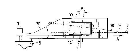
Fig. 1 is a side view of an outhaul device.
Fig. 2 is a plan view of the outhaul device illustrated in fig. 1.
Fig. 3 is a front view of only the two wheels of the outhaul device.
The terms up and down should be understood to indicate directions towards t
S the edge of the page which faces away from and towards the reader
respectively.
As illustrated in figs. 1 and 2 a fishing line 2 extends rectilinearly between apair of wheels 4,6 from a line store 3, via a spool device, at the left side of
the page towards the right as indicated by the arrow A, the line store 3 being
attached to the hull of a vessel 5 of which only a part is shown. The wheels
4,6 can be rotated about their symmetry axes of rotation 8 and 10
respectively by means of a suitable drive device, e.g. hydraulic motors (not
shown), both wheels preferably being driven. The symmetry axes extend in a
common plane which extends substantially perpendicularly to the line
hauling direction. The wheels' contact surfaces 12, 14 abut against each
other, thus pressing the line against the respective contact surfaces. One
contact surface, e.g. contact surface 12, can be made of an elastically
yielding material, e.g. rubber, thus enabling the securing devices 16 whereby
snells 18 are attached to the line 2 to be received by this contact surface and
pass the wheels during line hauling. The second wheel's contact surface is
preferably provided with a pattern such as a serration in order to ensure a
good connection between the wheel and the line.
In order to prevent the fishing hooks on the snells which have been supplied
with bait from being squeezed between the wheels and the bait destroyed, at
the wheels there is provided a ramp 30 which extends from a point in front of
the wheels 12,14, considered in the line hauling direction? to a point above
the wheels. From this point the ramp extends past the wheels to a point on
the downstream side thereof.
The ramp 30 has a groove 32 through which the line 2 extends, and which is
so wide that the securing devices 16 can also be passed through the groove.
The width of the groove, however, is so small that the hool~s with bait
attached cannot pass through the groove.

CA 02228406 1998-01-30
W O 97/46089 PCT~097/00139
Thus when the line 2 iS hauled, the line will be able to pass rectilinearly froma point on the upstream side of the outhaul device, between the wheels 4,6 of
the outhaul device to a point on the downstream side of the outhaul device,
drawing the snells along with it. When a fishing hook on a snell reaches the
S ramp, however, it will be displaced upwards along it, since it or the bait rests
on the groove's lateral edge sections, above and past the wheels 4,6, and fall
freely down from the ramp behind them and out into the water.
By guiding the line linearly between the wheels 4,6 and the arrangement of
the ramp 30, it becomes possible for the snells 18 to be connected to the line
10 and baited on the upstream side of the outhaul device, thus permitting an
automatic connection of the snells 18 with the line and automatic baiting of
the snells' fishing hooks.
In order to ensure that the wheels 4,6 are pressed with sufficient force againsteach other, providing a sufficient amount of friction between the line and the
contact surfaces 12,14, pressing devices such as hydraulic jacks 34,36 can be
employed which influence the respective wheels, e.g. via rollers which abut
against the contact surfaces, these jacks being attached to stationary parts
(not shown) of the outhaul device.
As illustrated in fig. 1, the wheels 4,6 can be tilted in a plane which includes20 the respective wheels' axes of rotation and are perpendicular to the common
plane for the wheels' axes of rotation, as indicated by the angle B, thus
preventing the line from being dislocated, i.e. being moved up and out of
engagement with the wheels.
Furthermore, the wheels can be arranged for tilting in the common plane for
the wheels' axes of rotation as illustrated in fig. 3. The lower sections of thecontact surfaces 12,14 are thereby pressed very hard against each other, thus
achieving a particularly strong pressing of these contact surface sections
against the line. A further achievement is that other contact surface sections
do not come into contact with one another, thus reducing the wheels' rolling
30 resistance and the power which is required for driving the wheels.
If the wheels' drive devices are controlled by a programmable logic control
device (not shown) and suitable sensors (not shown) which are connected
thereto, the wheels may be stopped automatically if the line and the snells
become tangled and the tractive power in the line 2 during hauling exceeds a

CA 02228406 1998-01-30
WO 97/46089 PC~N097/00139
predetermined value. Moreover, an automatic regulation of the wheels'
rotational speed can be achieved, thus enabling the speed at which the line is
deployed in the water to be adapted to the speed of the vessel.

Representative Drawing
A single figure which represents the drawing illustrating the invention.
Administrative Status

2024-08-01:As part of the Next Generation Patents (NGP) transition, the Canadian Patents Database (CPD) now contains a more detailed Event History, which replicates the Event Log of our new back-office solution.

Please note that "Inactive:" events refers to events no longer in use in our new back-office solution.

For a clearer understanding of the status of the application/patent presented on this page, the site Disclaimer , as well as the definitions for Patent , Event History , Maintenance Fee  and Payment History  should be consulted.

Event History

Description Date
Time Limit for Reversal Expired 2003-06-02
Application Not Reinstated by Deadline 2003-06-02
Inactive: Abandon-RFE+Late fee unpaid-Correspondence sent 2002-06-03
Deemed Abandoned - Failure to Respond to Maintenance Fee Notice 2002-06-03
Inactive: IPC assigned 1998-05-11
Inactive: First IPC assigned 1998-05-11
Classification Modified 1998-05-11
Inactive: Notice - National entry - No RFE 1998-04-24
Application Received - PCT 1998-04-23
Application Published (Open to Public Inspection) 1997-12-11

Abandonment History

Abandonment Date Reason Reinstatement Date
2002-06-03

Maintenance Fee

The last payment was received on 2001-05-04

Note : If the full payment has not been received on or before the date indicated, a further fee may be required which may be one of the following

  • the reinstatement fee;
  • the late payment fee; or
  • additional fee to reverse deemed expiry.

Patent fees are adjusted on the 1st of January every year. The amounts above are the current amounts if received by December 31 of the current year.
Please refer to the CIPO Patent Fees web page to see all current fee amounts.

Fee History

Fee Type Anniversary Year Due Date Paid Date
Basic national fee - standard 1998-01-30
Registration of a document 1998-01-30
MF (application, 2nd anniv.) - standard 02 1999-06-02 1999-04-30
MF (application, 3rd anniv.) - standard 03 2000-06-02 2000-05-01
MF (application, 4th anniv.) - standard 04 2001-06-04 2001-05-04
Owners on Record

Note: Records showing the ownership history in alphabetical order.

Current Owners on Record
O. MUSTAD & SON A/S
Past Owners on Record
GEIR ROGNE
HILBERT JOHANSEN
JAN MARTIN HANSEN
Past Owners that do not appear in the "Owners on Record" listing will appear in other documentation within the application.
Documents

To view selected files, please enter reCAPTCHA code :


To view images, click a link in the Document Description column. To download the documents, select one or more checkboxes in the first column and then click the "Download Selected in PDF format (Zip Archive)" or the "Download Selected as Single PDF" button.

List of published and non-published patent-specific documents on the CPD .

If you have any difficulty accessing content, you can call the Client Service Centre at 1-866-997-1936 or send them an e-mail at CIPO Client Service Centre.


Document
Description 
Date
(yyyy-mm-dd) 
Number of pages   Size of Image (KB) 
Representative drawing 1998-05-11 1 6
Abstract 1998-01-29 1 43
Description 1998-01-29 4 179
Claims 1998-01-29 2 76
Drawings 1998-01-29 1 18
Notice of National Entry 1998-04-23 1 193
Courtesy - Certificate of registration (related document(s)) 1998-04-23 1 117
Reminder of maintenance fee due 1999-02-02 1 110
Reminder - Request for Examination 2002-02-04 1 117
Courtesy - Abandonment Letter (Request for Examination) 2002-07-28 1 171
Courtesy - Abandonment Letter (Maintenance Fee) 2002-07-01 1 183
PCT 1998-01-29 3 111
Fees 2001-05-03 1 38
Fees 1999-04-29 1 42
Fees 2000-04-30 1 38