Note: Descriptions are shown in the official language in which they were submitted.
CA 02228810 1998-02-0~
W O 97/073Z2 PCT~US96/13116
SPl~ING BRAKE ACTUATOR
RELEASE TOOL
I~ACKGROUND OF THE; INVENTION
This Application relates to an improved release tool for a spring brake
actuator that cages the power spring of the brake actuator with little or no axial
movement outwardly of the actuator housing.
Spring brake actuators are utilized on modern heavy vehicles to actuate a
brake when the vehicle is parked, or when a portion of the vehicle brake system
fails. In either situation, a powerful spring expands to move a merh~nic~l rod that
actuates the brake actuator. This actuation will sometimes occur while the vehicle
is on the road. An operator of the vehicle will then need to cage the spring such
that the vehicle may be moved. Servicing of a spring brake actuator and, in
particular, servicing of the parking side (where the power spring is located), is not
recommenrled Even so, in the event that one does attempt to open the parking side,
the spring must be caged by a mPçh~nical element prior to any such opening. The
power spring is also typically caged when the actuator is removed. installed or when
the vehicle is towed.
Thus, release tools have typically been provided in the parking side of a
spring brake actuator. The release tools have typically been a bolt that is received
within a piston that holds the power spring. When the bolt is turned it pulls the
power spring piston toward an outer end of the housing, holding or "caging" the
spring. The bolt has typically moved axially outwardly of the housing as it is
turned. Thus, in prior art spring brake actuators, the release bolt typically extends
axially outwardly from an outer end of the brake actuator housing when the powerspring is fully caged.
CA 02228810 1998-02-0~
W O 97/07322 PCTAJS96/13116
While this type of release bolt has proven successful, in many applications,
there may not be sufficient axial room for the release bolt to extend axially from the
brake actuator. Thus, there are desirable benefits to providing a release bolt that
does not extend axially away from the actuator when the power spring is caged.
5 The prior art has not succes~fully provided an arrangement to achieve the goal of
allowing reliable caging of the power spring, while at the same time not requiring
additional axial clearance at the outer end of the spring brake actuator chamber.
S-JMMARY OF THE INVENTION
In a disclosed embodiment of this invention, a spring brake actuator is
provided with a release tool that extends little or not at all axially outwardly beyond
its initial position as it cages the power spring. In p,efell~d embo-iimPnt~ of this
invention, a release bolt has a head ~rcP$cihle from outside the brake actuator
housing. The bolt engages an internal threaded nut. Turning the head of the bolt
moves the nut axially. The nut engages and moves a spring piston. The spring
piston is thus pulled axially toward an outer end of the brake housing, caging the
power spring. The bolt head does not move axially away from the brake actuator
head during this movement, and thus additional axial space outwardly of the brake
actuator is not necessary.
In other preferred features, the nut is initially m~int~ined by a spring at a
location such that it is aligned with an initial thread on the bolt. When an u~eldtor
begins to turn the bolt, the nut is imme li~tPly engaged by the thread and begins to
be withdrawn toward the outer end of the housing. On the other hand, since the nut
is initially not actually engaged with the thread, should an operator begin to turn the
CA 02228810 1998-02-0~
W O 97/07322 PCT~US96/13116
bolt in the wrong direction, the nut will not be driven away from the outer end of
the brake actuator. In this way, the present invention insures that there is notmovement of the nut in a direction that would impede the normal operation of thebrake actuator.
S In another feature of this invention, the nut has an outer periphery that
m~tchPs the profile of an inner bore in the piston. The nut may slide within this
inner bore during normal operation of the brake.
In one embodiment, a spring biases the nut towards the bolt. Before the nut
contacts the spring piston, this spring will bias the nut and bolt slightly axially
outwardly. The bolt extends a small distance away from the outer portion of the
brake actuator housing. An observer seeing this bolt head spaced slightly axially
outwardly from the housing will know that the brake actuator is uncaged. In thisembo~iment, when the operator begins to turn the bolt, the nut eventually contacts
a flange on the spring piston, begins to cage the power spring and takes up the
1~ clear~nce. Initially after this contact, the spring force which is biasing the nut
outwardly is first overcome, such that the bolt head does move inwardly from thepower spring is completely caged before the outward position discussed above. Anobse;ver seeing the bolt head in this position will recognize that the power spring
is partially or fully caged. Most preferably, a snap ring on the bolt abuts the inner
side of the housing when the bolt is moved outwardly by the spring to its outer
position. This snap ring defines a stop limiting outward movement of the bolt.
In other features, an O-ring is positioned on an outer peripheral surface of
the bolt at a position such that it provides a seal with the outer housing, and during
movement of the bolt as described above. This O-ring in conjunction with the
CA 02228810 1998-02-0~
W O 97/07322 PCT~US96/13116
spring at an inner end of the bolt provides a centering force to stabilize the bolt and
dampen the effect of vibrations on the bolt.
In other embo-iiment~, the bolt may be utilized without the small spring. In
this embodiment, the bolt does not pop up when uncaged, and the nut is received
5 on threads at all times. Other operational aspects of this embodiment are similar to
those ~ cu~e~ above.
Further, in other features, the invention includes a hollow push rod that
receives a portion of the length of the bolt and the nut. In this way, the length of
the release bolt does not increase the overall length of the brake actuator. Rather
10 a portion of the length of the release bolt may extend axially inwardly beyond the
power spring and into the push rod to reduce the re~uired outer envelope size for
the brake actuator.
In other features, the invention may be utilized on either piston or diaphragm
brakes.
In a method of operating a spring brake actuator to cage a power spring
according to the present invention, a bolt is received within a threaded nut. The nut
is received within a portion of a spring piston such that when the bolt is turned the
nut engages the spring piston and draws it toward an outer end of the brake housing
head. The method includes the steps of turning the release bolt head, thereby
20 turning the nut until the nut engages the spring piston. The method further
envisions continued turning of the head such that the nut begins to move the spring
piston until the spring is fully caged.
With the inventive type of release bolt described above, one issue that does
arise is that it is somewhat difficult to identify when the release bolt is fully
CA 02228810 1998-02-0~
W O 97/07322 PCT~US96/13116
r~ A. If the release bolt does not fully release the power spring, then the brake
cannot extend to its maximum effective stroke. This would be undesirable. For
that reason, further embo~liment~ of the present invention provide a structure visible
from outside of the brake that provides an indication of whether the release bolt has
5 been fully rele~ed.
In one emboriim~ont, a pop-up in-iic~tclr is included into the release bolt that
extends outwardly of the brake if the power spring has not been fully r~le~ced The
pop-up in-lir~tor is preferably formed of a bright color such that it may be easily
visible. A worker seeing the pop-up indicator would know that the brake has not
10 been fully released.
In a further ple~élled embodiment, the release bolt itself has two threaded
portions, with the threads e~t~n~iing in opposing directions. An inner threaded
portion is received in the nut as described above. An outer threaded portion, which
is formed integrally with the inner threaded portion, is threadably received in an
15 outer nut. When one turns this release bolt the outer threaded portion moves in the
outer nut and the bolt extends outwardly of the brake, pulling the inner portion, and
the nut, outwardly. At the same time, the inner threaded portion will be turning in
its release nut, which then moves upwardly. Thus, the release nut is being moved
relative to the push rod and power spring by both threaded portions. In this way,
20 the outer portion will extend outwardly of the brake housing, but only for a
relatively small amount. The observer of this brake will be able to identify whether
the brake has been fully released by looking to see whether the release bolt is moved
~ inwardly against the outer surface of the brake housing. If so, then one knows the
brake has been fully released.
CA 02228810 1998-02-0~
W O 97/07322 PCT~US96/13116
These and other features of the present invention can be best understood
from the following specification and drawings, of which the following is a briefdescription.
BRIEF DESCRIPI'ION OF THE DRAWINGS
Figure l is a partially cross-sectional view of a spring brake actuator
incc,l~old~ g the present invention.
Figure 2 is a cross-sectional view along line 2-2 as shown in Figure l.
Figure 3 is a cross-sectional view of the spring brake actuator moving
towards the actuated position.
Figure 4 shows the spring brake actuator of Figure l with the spring caged.
Figure 5 shows a second embodiment release bolt.
Figure 6A shows a third embodiment brake actuator.
Figure 6B shows the embodiment of Figure 6A having moved to a different
operational position.
Figure 6C shows the embodiment of Figure 6A having moved to yet another
operational position.
Figure 7 shows another embodiment brake in a first condition.
Figure 8 shows the Figure 7 embodiment in a subsequent position.
Figure 9 shows yet another subsequent position.
Figure 10 shows yet another subsequent position.
Figure 11 shows yet another embodiment of the release tool of this invention.
Figure 12 shows the Figure 11 embodiment in an extended position.
Figure 13 shows the Figure 11 embodiment in its caged position.
DETAILED DESCRIPrION OF A PREFERR~D EMBODIMENT
CA 02228810 1998-02-0~
W O 97/07322 PCT~US96/13116
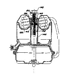
Figure 1 shows a spring brake actuator 20. The structure of the spring brake
actuator other than that relating to the release tool mPcll~nicm is as known in the art.
Thus, a det5~iled description of all components of the brake actuator will not be
inf~ ed. As is known, a spring brake actuator includes a central housing body 22,
5 typically referred to as a flange case that connects an outer brake housing
member 24, sometimes known as a head to an inner brake housing 26, sometim~s
known as a service chamber. Within the head is a power spring 28. Spring 28
selectively engages a brake through the yoke 27 upon certain conditions, as known.
A chamber 30 is defined beneath a diaphragm 32. When pressurized air is received
within chamber 30, diaphragm 32 moves upwardly colllplessillg the spring 28. In
that condition, a push rod 34 ~ccoci~tPd with the diaphragm 32 is also moved
upwardly. In this position, the spring 28 is not ~ t~-~fP~I, and the push rod 34 is not
forced downwardly. The parking side of the brake actuator thus does not move the
yoke 27 to actuate the brake. When the parking brakes are turned on, or if there
lS is some failure in the system, then spring 28 expands, forcing the push rod 34
downwardly to move the yoke 27 outwardly.
The spring 28 is received on a spring piston 36. A release bolt 38 extends
through the brake housing 24. An O-ring seal 39 provides an air-tight seal between
bolt 38 and the housing portion 24. A threaded bolt portion 40 extends from the
bolt head 41. A nut 42 is received on the bolt 38 at an inner end of the housing 24.
The nut 42 is received within a bore 44 in the piston 36. Spring 46 biases the
nut 42 to a position such that the threads within the nut 42 are aligned with the
~ beginning thread 48 of the threaded portion 40. The portion 49 below thread 48 is
not threaded. Thus, should the bolt head 41 be turned in a first direction, the
--7-
CA 02228810 1998-02-0~
W O 97/07322 PCTrUS96/13116
thread 48 will be çng~gP~I on threads 42, and the nut will begin to be drawn
upwardly on the threaded portion 40. On the other hand, should the head 41 be
turned in the opposed direction, the nut 42 will not be drawn onto the thread 48 and
the nut 42 will not be moving onto the threaded portion 40.
As also shown in Figure 1, the small spring 46 has biased the bolt head 41
to a position such that there is a slight clearance 70 between the bolt head 41 and
the housing 44. A snap ring 64 prevents further outward movement of the bolt 38.The spring 46 biases the nut 42 and hence the bolt 38 outwardly to this position.
An observer of the clearance 70 will know that the power spring 28 remains
uncaged in a brake actuator 20.
As shown in Figure 2, the bore portion 44 has an inner periphery that
corresponds to the outer periphery of the nut 42. In this illustration the nut and
bore are both shown as being hexagonal, although other cross sections may well
come within the scope of this invention. As also shown, a lower unthreaded
portion 49 of the bolt 38 is received within a bore 52 of the nut 42. Bore 52 isthreaded.
As shown in Figure 3, when the spring 28 expands it moves the piston 36
downwardly along with the push rod 34. This movement does not affect the releasetool since the nut 42 slides in bore 44. That is, as the spring 28 moves from the
position shown in Figure 1 to the position shown in Figure 3, the nut 42 merely
slides within the bore 44. As shown in Figure 3, it is possible to design a longspring which will keep clearance 70 during this movement. The observer will knowthat the power spring 28 remains uncaged.
CA 02228810 1998-02-0~
W O 97/07322 PCTAUS96/13116
In some in~t~n~es, when the brake actuator is in the exp~n~ed position, an
~e.~r would like to capture or cage the power spring 38 mecll~nic~lly from
outside of the brake actuator 20. The prior art has typically provided a release bolt
which is turned to move a mtoch~ni(~l member within the housing to capture the
S spring 28.
As shown in Figure 4, tool 60 may begin to turn the head 41 of the bolt 38.
Upon initially turning the bolt 38, the nut 42 will be engaged on the threads of the
threaded portion 40. Continued turning of the head 41 will cause the nut 42 to
move axially upwardly along the threaded portion 40.
Eventually, the nut 42 contacts a flange 62 at an outer end of the piston 36.
At that time, continued turning of the bolt head 41 causes the nut 42 to move the
piston 36. This movement captures or cages the spring 28. As the nut initially
contacts flange 62, the first movement that occurs is the movement of the bolt head
41 inwardly towards the housing 24. After the nut 42 contacts flange 62, the force
of the spring 46 no longer biases the nut outwardly. Rather, as the nut turns, the
nut and bolt move inwardly to elimin~te clearance 70. Upon further tightening, the
nut 42 begins to draw the flange 62, piston 36, and hence spring 28 to the caged
position such as shown in Figure 4. Thus, an observer seeing there is no longer a
clearance 70 would recognize that the power spring is partially or fully caged.
Figure S shows another embodiment actuator 80. In actuator 80, there is no
small spring. The spring piston 82 includes a bore 84 as in the previous
embodiment. A nut 86 rides along a bolt 88. Upon turning of the bolt 88, the nut
~ 86 moves axially within the bore 84 as in the above embodiment. There are threads
90 along the length of the bolt 88, and the nut 86 is always received on the threads
CA 02228810 1998-02-0~
W O 97/07322 PCT~US96/13116
9û in a ~ ,relled embodiment. Flange 92 extends inwardly from the piston 82. As
the bolt 88 is turned, the nut 86 moves and eventually contacts the flange 92.
Continued turning of the bolt head 88 cages the spring as in the previous
embo-limP,nt
S The brake actuators shown in Figures 1-5 utilize diaphragms as their
~t--~ting member in the spring chamber. The embodiment 80 shown in
Figure 6A-6B disclose a piston type brake actuator. Other features of a embodiment
80 are also shown in a Figure 6A-6C embodiment. It should be understood that thefea~ur~s generally shown for the release tool in Figures 6A-6C would also find
benefits in diaphragm brakes. Moreover, the release tools shown in Figures 1-5
may also find benefits in piston brakes.
As shown in Figure 6A, a piston brake 80 incorporates a housing member
82 that is comlecled to a central housing 84, as with a clip 86 or other known
connection. A power spring 88 biases a piston 90 outwardly. Piston 90 moves witha push rod 92 to actuate a yoke as in the previous embodiments. Push rod 92 is
formed with a bore 94, and a bolt 96 extends downwardly into bore 94. A nut 98
is biased upwardly by a small spring 99 as in the prior embodiment. As shown,
bolt 96 is thus spaced by a small amount 97 from the outer housing 82, again to
provide an indication to an observer that the power spring is not caged. In thisembodiment, since the bolt 96 extends into the push rod 92, brake actuator 80 may
be of a relatively smaller axial outer envelope size than if the push rod 92 were
solid. A portion of the bolt length is thus taken up by having it extend into the
hollow push rod 92. As shown, the push rod 92 extends through an opening 100
-10-
CA 02228810 1998-02-0~
W O 97/07322 PCT~US96/13116
in the central housing 84. In the position shown in Figure 6A, the power spring 88
is co.l.plc~ed by air pressure in the chamber beneath the piston 90.
As shown in Figure 6B, the power spring 88 has now expanded to drive the
piston 90 against the center housing 84. The push rod 92 extends through the
S opening 100, and the yoke is ~ctll~t~A as is known. As also shown, the nut 98 is
slightly spaced from the flange 102 in this position. The clearance 97 remains in
this position, and the rlimen~ions are preferably selectecl such that the piston 90
bottoms out on the housing 84 before the flange 102 contacts the nut 98 and
overcomes the small force of the spring 99. Thus, an observer will also be able to
10 tell that the power spring 88 remains uncaged in this position.
As shown in Figure 6C, the bolt 96 has now been turned to move the nut 98
and cage the piston 90 and power spring 88. Although the hollow push rod concept
has been illustrated with the small return spring embodiment as discussed above, it
should be understood that the embodiment shown in Figure S wherein there is no
15 spring could also be combined with this hollow push rod embo-limer~t
In a method of caging a brake actuator according to the present invention,
one initially provides a brake actuator with a threaded release tool that may be
turned to cage a power spring without moving the tool axially away from the
housing member. In a p~c;fel~c~d embodiment, the method includes the steps of
20 providing such a release tool which threadably engages a nut, with the nut moving
axially when turned by the release bolt to cage the power spring. The method
further includes the steps of beginning to turn the release bolt to move the nut and
cage the power spring.
CA 02228810 1998-02-0~
W O 97/07322 PCTrUS96/13116
With the above described release tool, it may be difficult to identify whether
the brake is fully released from outside of the brake. Thus, embo-liment~ of theinvention having indication structure which is visible from outside of the brake have
also been developed.
A first embodiment 110 is illustrated in Figure 7. A push rod 112 receives
a nut 114 as in above-described embodiment. A spring piston 116 provides a stop
for the nut 114 as in the above embodiment. A cap 118 is received on a pop-up
inrlic~tQr rod 120. A spring 124 reacts off of the release bolt 123 at a ledge portion
122. Spring 124 forces a head 126 of the indicator 120 outwardly of the brake
housing. The head 126 is preferably formed of a bright color. An observer seeingthe bright head will know that the brake is not fully re!~ ed As an example, in
Figure 7, the brake is shown fully caged. Thus, the head 126 can move relative to
the bolt 123 and the ledge 122.
As shown in Figure 8, the release nut 114 has been moved downwardly, but
has not yet fully released the spring. Thus, the spring is not able to extend to its
full stroke. It would be desirable to provide an indication that the operator has not
yet fully released the brake. As shown in this figure, the spring 124 continues to
bias head 126 outwardly of the brake.
As shown in Figure 9, the release nut 114 has been moved further and has
now fully released the brake. The release nut 114 has now abutted cap 118, and
pulled cap 118 inwardly. This in turn pulls the rod 120 and head 126 against theforce of the spring 124. As shown, the head 126 is no longer extending outwardlyof the cap. An observer will now know that the brake has been fully rele~e~l
CA 02228810 1998-02-0~
W O 97/07322 PCT~US96/13116
As shown in Figure 10, since the nut 114 has fully released the brake, the
spring may extend to its full stroke. Again, the head 126 does not extend outwardly
of the brake in this condition.
Figure 11 shows another embodiment 140 having a release bolt 142. Release
bolt 142 turns an inner release nut 144, which moves within a push rod 146 in a
manner such as described with the above embodiments. Release bolt 142 also has
an outer nut 148. Release bolt 142 has two integral threaded portions lS0 and 152.
The threads on portions lS0 and lS2 extend in opposed directions. The threads onportion lS0 turn within outer nut 148 and the threads on portion 152 turn withininner nut 144.
In the position shown in Figure 11, the release bolt 142 has fully released
the brake. Note that the release bolt 142 does not extend at all outwardly of the
housing.
As shown in Figure 12, in this location, the push rod 146 can extend under
lS the influence of a power spring 154 to its full extent. Again, the bolt 142 does not
extend outwardly of the housing, and an observer will be able to see that the brake
has been fully released.
When one wishes to cage the power spring, one turns the bolt head 142.
The thread 152 turns within nut 144, and the nut 144 advances along thread 152 as
in the previous embodiments. However, at the same time, the thread 150 is turning
within the outer nut 148, and thus the thread 150 is moving outwardly of the
housing. As the thread lS0 moves so does the bolt 142, and hence the nut 144.
Thus, in essence, when one turns the nut 142, the thread 150 does cause the bolt142 to move outwardly of the housing. However, there is an amplification of the
CA 02228810 1998-02-0~
W O 97/07322 PCT~US96/13116
caging of the nut 144 due to the second thread 152. For that reason, the bolt 142
need only move outwardly of the housing a relatively small amount such as shown
in Figure 13 to achieve full caging of the power spring.
Although ~.'t;rt;ll~d embodiments of this invention have been disclosed, a
5 worker of ordinary skill in the art would recognize that certain modifications would
come within the scope of this invention. For that reason, the following claims
should be studied to determine the true scope and content of this invention.
-14-