Note: Descriptions are shown in the official language in which they were submitted.
CA 02228857 1998-04-17
FAUCET-LIKE BIDET ATTACHMENT
BACKGROUND OF THE INVENTION
FIELD OF THE INVENTION
This invention relates generally to bidet devices for cleansing the anal and
genital areas of the human body, and more particularly to a simple, useful,
cost-effective, arid affordable faucet-like bidet device for use in
conjunction with a
conventional flu:>h toilet.
BRIEF DESCRIPTION OF THE PRIOR ART
Hygienic cleansing devices, more specifically bidets, are well known in
many parts of the world. Their worldwide acceptance, as part of personal
hygiene
are promising. T he concept of bidets is relatively old, going back at least
as early as
1881, in U.S. Patent No. 244,219.
Bidets are typically a stand-alone bathroom fixture, having substantially
the same size and configuration as an ordinary flush toilet, with hot and cold
water
taps for producing a relatively comfortable temperature for cleansing
purposes. In
some cases, nozzles or spray heads are provided to direct the flow of water to
the
desired area to b~e cleansed.
Notwithstanding their positive contribution to personal hygiene, however,
bidets have failed to significantly impact widespread acceptance, locally and
internationally. Space constraints may preclude the installation of a bidet in
many
existing bathrooms. Bidets often represent an additional plumbing fixture and
thus a
substantial expense is involved that some prospective consumers may find
difficult
to justify.
-2-
CA 02228857 1998-04-17
Most: conventional bidets, are typically bulky and awkward to use, and
require special plumbing to install. As a result, although the use of bidets
are
popular, where they are available, because of their complexity and unsightly
appearance, they have not become popular or commercially available. The lack
of
practicality, maybe the bottom line of consumers' passive attitude towards
this
remarkable device.
There are several patents which disclose various bidet devices and
apparatus. However, most of these devices are characterized by an undue level
of
mechanical complexity, which may affect their reliability and preclude their
economical manufacture and widespread acceptance. Existence of complicated
water supply conduits and mechanical arrangements are also common undesirable
features of the prior art.
Ibel, U.S. Patent No. 4,145,767 and Broyles, U.S. Patent No. 4,876,750
disclose composite water closet and bidet fixtures which are stand-alone
plumbing
fixtures that would replace the conventional toilet.
Huck. et al, U.S. Patent No. 4,406,025 discloses a bidet device having an
elongated vertical water heater storage vessel with a bottom inflow cold water
connection and a top outflow connection to the bidet attachment, that serves
as the
source for the warm water supply. Although it takes advantage of the toilet
bowl
for use as the bidet basin, there are a number of shortcomings in other
respects.
For example, the water heater storage vessel is an additional large fixture
requiring
additional space and adding to the cost, as well as additional maintenance
costs that
will be incurred later on. The existence of a bidet tube support assembly adds
another unnecessary feature and only contributes more to its complexity.
-3-
CA 02228857 1998-04-17
Nourbakhsh, U.S. Patent No. 4,596,058 discloses a water closet bidet
system having a hand held spray device which can be retracted into a
compartment
for storage. The need to use at least one hand during its operation is
obviously an
unwanted feature for users especially the handicapped. This awkward procedure,
which results in considerable inconvenience for users, is totally eliminated
by the
present invention.
Latora, U.S. Patent No. 5,271,104 discloses a toilet bidet attachment
having a hose that attaches to the toilet filler tube and may include an
electric
heater. The device has a rigid bidet arm that merely pivots to one side.
Lesic;k, U.S. Patent No. 4,195,369 discloses a removable toilet bidet
attachment in the form of a two-piece clamp that attaches to the rim of the
toilet
bowl and has a nozzle body fixed onto the clamp body and connected with fluid
passageways. The nozzle body is only pivotally adjustable about a horizontal
axis.
Smith, U.S. Patent No. 5,384,919 discloses a bidet attachment that is
secured to the underside of a toilet seat and has an elongated rigid water
pipe with
an upwardly directed nozzle and a lever. The water pipe is only pivotal about
a
horizontal axis.
McGuire, U.S. Patent No. 5,495,625 discloses a toilet bowl bidet
attachment which has a rigid tube which extends through an aperture fornied in
the
toilet bowl. This device requires drilling a hole through the wall of the
toilet bowl.
Chandler, U.S. Patent No. 5,504,948 discloses a bidet attachment and
valve arrangement that is built into a toilet seat and has a rigid bidet arm
that merely
pivots to one side.
The foregoing patents demonstrate the failure to provide a bidet device of
simple construction, installation and operation.
-4-
CA 02228857 1998-04-17
The present invention is distinguished over the prior art in general, and
these patents in particular by a simple faucet-like bidet attachment which is
connected to existing hot water and cold water supply lines adjacent to a
conventional flush toilet. The bidet device has a control valve and a pliant S-
shaped
water conduit that extends from the control valve under the toilet seat,
curves over
the rim of the toilet bowl, then extends downwardly, and then curves back
upwardly
in the bowl. A spray nozzle attached to the upwardly extending free end of the
conduit produce s a comfortable bidet spray directed to the target area. The
pliant
S-shaped conduiit is easily adjusted according to each user's particular
preferences,
by simply bending or shaping it by hand. The control valve regulates the water
pressure and temperature that flows through the S-shaped water conduit, and in
a
preferred embodiment, provides hot, warm, or cold water temperature settings.
Alternatively, the control valve may provide hot and cold water, or just cold
water.
-5-
CA 02228857 2002-10-28
SUMMAKY OF THE INVENTION
Accordingly, the present invention seeks to provide a simple, efficient and
economical approach to personal hygiene and a cleansing process that is
totally hands free.
Further, this invention seeks to provide a faucet-like bidet device having a
pliant S-shaped water conduit and a nozzle at one end that is easily shaped or
bent by hand
to the particular preferences of each user and freely-adjustable within a
concentrated area
to properly and selectively position the nozzle.
Further still, this invention seeks to provide a faucet-like bidet device
which
conserves space and utilizes existing hot and cold water connections as well
as utilizing the
toilet bowl as a bidet basin.
Still further the invention seeks to provide a simple and affordable bidet
device
that connects easily and quickly to existing hat and cold plumbing connections
and has an
easily maneuverable S-shaped bidet water conduit and does not require
unnecessary
attachments or support.
Yet further this invention seeks to provide a bidet device having a control
valve that allows the user to select three preset water temperature
selections, e.g. hot, warm
and cold and prevent abrupt and uncomfortable water temperature changes during
the time
of usage and/or at the start of each use.
Moreover this invention seeks to provide a bidet device having a nozzle
assembly which will neutralize the water pressure so as to provide additional
comfort to the
bidet user.
-6-
CA 02228857 2002-10-28
Briefly, the invention provides a simple faucet-like bidet attachment which is
connected to existing hot water and cola water supply lines adjacent to a
conventional flush
toilet. The bidet device has a control valve and a pliarxt S-shaped water
conduit that extends
from the control valve under the toilet seat, curves over the rim of the
toilet bowl, then
extends downwardly and then curves back upwardly in the bowl. A spray nozzle
attached
to the upwardly extending free enci of the conduit produces a comfortable
bidet spray
directed to the target area. The pliant S-shaped conduit is easily adjusted
according to each
user's particular preferences, by simply bending or shaping it by hand. The
control valve
regulates the water pressure and temperature that flows through the S-shaped
water conduit
and in a preferred embodiment, provides hot, warm, or cold water temperature
settings.
Alternatively, the control valve may provide hot and cold water, ar just cold
water.
Other aspects of the invention will hecome apparent from time to time
throughout the specification and claims as hereinafter related.
BRIEF DESCRIPTION OF THE DRAWINGS
Fig. 1 is a perspective view of a preferred embodiment of a bidet device in
accordance with the present invention shown installed adjacent to an existing
conventional
flush toilet fixture.
Fig. Z is a perspective view of a preferred embodiment of the faucet-like
control valve of the bidet device showing the outer housing in dashed line.
CA 02228857 1998-04-17
Fig. 3 is an exploded isometric view showing the components of the
control valve in an unassembled condition and showing various cam disc
elements to
allow adjustable settings for hot, warm, or cold water.
Fig. 4 is an end view of the control valve body with the valve assembly
removed and showing the S-shaped water conduit with a nozzle at one end and
various fittings at the other end for connecting it to the control valve.
DESCRIPTION OF THE PREFERRED EMBODIMENTS
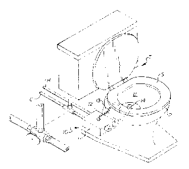
Referring to the drawings by numerals of reference, there is shown in
Figs. 1, 2, 3, and 4, a preferred bidet attachment device 10 in accordance
with the
present invention for use in connection with a conventional flush toilet T.
The bidet
device 10 has a faucet-like control valve 12 which may be enclosed inside a
box-like housing 11. Optionally, the box-like housing 11 may be omitted. As
described in detail hereinafter, the control valve 12 of the bidet device 10
is
connected to the existing cold water supply line C and hot water supply line
H.
A pliant S-shaped water conduit 13 connected at one end to the control
valve 12 extends. under the toilet seat S, curves over the rim R of the
toilet: bowl B,
then extends downwardly, and then curves back upwardly inside the bowl. A
spray
nozzle 14 is attached to the upwardly extending free end of the conduit 12.
The
pliant water conduit 13 may be easily manually adjusted to assume various
positions, as indicated by opposed arrows in Fig. l, and thereby direct a
spray of
water from the nozzle 14 to the desired target area. The control valve 12
regulates
the water pressure and temperature that flows through the S-shaped water
conduit
13.
_g_
CA 02228857 1998-04-17
A preferred embodiment of the control valve l 2 is shown in an assembled
condition in Fig;. 2 and an exploded unassembled condition in Fig. 3. As best
seen
in Figs. 3 and 4, the control valve assembly 12 includes a valve body 15 with
a
semi-spherical concave chamber 16, and an interior cold water inlet port 17, a
hot
water inlet port 18, and a water outlet port 19 in fluid communication with
the
chamber 16 (Fig. 4). A cold water inlet conduit 20 extends from the cold water
inlet
port 17 and has a fitting such as a compression nut fitting 21 which connects
to the
existing cold water supply line C. A hot water inlet conduit 22 (Fig. 2)
extends from
the hot water inlet port 18 (Fig. 4) and has a fitting such as a compression
nut
fitting 23 which connects to the existing hot water supply line H. A water
outlet
nipple 24 in fluid communication with the water outlet port 19 extends
outwardly
from the side wall of the valve body 15.
A ball valve assembly is installed in the semi-spherical concave chamber
16 of the valve body 15. The valve assembly includes a pair of springs 25 and
rubber valve seats 26, one set of each installed in the cold and hot inlet
ports 17 and
18. A hollow ball valve 27 having an outwardly extending stem 27A is rotatably
mounted in the semi-spherical chamber 16. The ball valve has a slot 27B, a
cold
water aperture 27C, a hot water aperture 27D and a water outlet aperture 27E
formed in its side wall. The slot 27B in the side wall of the ball valve 27 is
received
on an inwardly protruding pin 15A on the interior of the valve body 15 (Fig.
4) to
allow the ball valve to rotate and thereby control flow through the apertures
in its
side wall, as explained hereinafter.
-9-
CA 02228857 1998-04-17
A seal disc 28 having a central opening 28A and a concave inner surface
28B is received in the valve body and engages the ball valve 27 with the stem
27A
of the ball valve extending through the opening. A selected disc-shaped cam
member, designated generally as 29, is installed on the seal disc 28 and has
an
outwardly protruding tab 29A which is received in a slot 15B formed in the
valve
body 15. A cup-shaped cap 30 having internal threads at one end is threadedly
engaged on external threads l5C formed on the valve body 15 (Fig. 3) and has
an
internally threaded bore 30A at its opposite end. The cap 30 holds all the
components together. A hollow cylindrical externally threaded seal insert 31
is
threadedly received in the threaded bore 30A of the cap 30 and engages the cam
member 29 to apply a compressive force to the assembled components to effect a
water-tight seal sealing relation. The sealing force can be adjusted by
tightening or
loosening the insert 31 with a tool (not shown) which is received in
circumferentially spaced slots 31A in the outer end of the insert. The stem
27A of
the ball valve 27 extends through the cam member 29 and the insert 31. A
handle
32 having a concave cup-shaped base 32A is secured to the stem 27A and the cup
shaped base overlaps the outer end of the cap 30.
When the ball valve 27 is rotated by moving the handle to the left or
right, its cold and hot apertures 27C and 27D pass across the cold and hot
water
inlet ports 17 and 18 in the valve body 15 allowing them to be closed,
partially
opened, or fully opened and the water is mixed inside the hollow spherical
ball.
When the handle; is moved up or down, the water outlet 27E passes across the
water
outlet port 19 in the valve body allowing it to be closed, partially opened,
or fully
opened, thereby adjusting the water pressure of the discharged water.
-10-
CA 02228857 1998-04-17
Fig. 3 shows various interchangeable cam members 29 having different
apertures which may be used to allow the ball valve to be pre-set or
positioned to
provide the des iced water pressure and to supply water of hot, warm, or cold
temperatures. one cam member 29B has a central aperture with three adjacent
curved recesses :'9C, 29D, and 29E at its lower end.
Alternatively, as represented by 29F, the central aperture may be formed
of three adjacent slots 29G, 29H, and 29I joined together at their upper ends.
In
these cam embodiments, when the stem 27A is in the left-hand recess 29C or
slot
29G, only cold water is provided, when in the central slot 29D or recess 29H
the hot
water mixes with the cold water to provide warm water, and when in the right-
hand
recess 29E or slot 29I, only hot water is provided. When the stem 27A is in
the
upper end of the recesses or slots, the water is turned off.
Another pair of cam members 29J and 29M each have a central aperture
through which the stem 27A of the ball valve 27 passes that allows the ball
valve to
be pre-set or positioned to supply water of only hot or cold temperatures. As
represented by numeral 29J, the apertured cam disc may have two adjacent
straight
sided parallel slots 29K and 29L joined at their upper ends, or, as
represented by
numeral 29M; may have an oval-shaped recess with rounded ends 29N and 29P.
When the stem :~7A is in the left-hand slot 29K or rounded end 29N cold water
is
produced, and when in the right-hand slot 29L or rounded end 29P hot water is
produced. When the stem 27A is in the upper end of the slots or centered
between
the rounded ends of the oval recess, the water is turned off.
-11-
CA 02228857 1998-04-17
The control valve may also be installed where there is no hot water supply
line or the installation of, or connection to, the hot water supply is not
available or
practical. In this installation, a plug 33 is provided which can be installed
in the end
of the hot water inlet conduit 22, and only cold water is produced. In this
arrangement, the previously described cam discs may be used, or a cam disc 29Q
may be provided having a single vertical slot 29R. When the stem 27A is in the
upper end of the slot 29R, the cold water is turned off.
Referring again to Fig. 4, the pliant S-shaped water conduit 13 is
connected at a first end to the outlet nipple 24 extending outwardly from the
side
wall the valve body 15. In a preferred embodiment, the pliant water conduit 13
is
approximately 1 /4" in diameter and may be formed of a chromeplated metal
material
or suitable plastic material. The first end of the water conduit 13 may be
connected
to the nipple 24 by a compression nut fitting 34 or, by a ball and socket type
swivel
connection 35, or, alternatively, by a tubular connector 36 that connects to
the nipple
24 and has internal 0-rings 37 that seal on the first end of the water conduit
13. As
described above, the water conduit 13 extends from the control valve 12 (Fig.
2),
under the toilet seat S, curves over the rim R of the toilet bowl B, then
extends
downwardly, and then curves back upwardly in the bowl (Fig. 1 ).
In the preferred embodiment, the nozzle 14 has a spray nozzle cap 14A
attached to a fitting 13A on the upwardly extending free end of the conduit
13. The
spray nozzle cap 14A contains a perforated disc 14B, and may also contain an
interior metal screen 14C. The perforated disc 14B and screen 14C neutralize
the
water pressure and strain out contaminants and debris, and produces a
comfortable
-12-
CA 02228857 1998-04-17
bidet spray directed to the target area. The S-shaped water conduit 13 can be
easily
adjusted according to each user's particular preferences, by simply bending or
shaping it by hand. It should be understood that the water conduit 13 may also
be
provided without the spray nozzle assembly 14. While this invention has been
described fully and completely with special emphasis upon a preferred
embodiment,
it should be understood that within the scope of the appended claims the
invention
may be practiced otherwise than as specifically described herein.
-13-