Language selection

Search

Patent 2228900 Summary

Third-party information liability

Some of the information on this Web page has been provided by external sources. The Government of Canada is not responsible for the accuracy, reliability or currency of the information supplied by external sources. Users wishing to rely upon this information should consult directly with the source of the information. Content provided by external sources is not subject to official languages, privacy and accessibility requirements.

Claims and Abstract availability

Any discrepancies in the text and image of the Claims and Abstract are due to differing posting times. Text of the Claims and Abstract are posted:

  • At the time the application is open to public inspection;
  • At the time of issue of the patent (grant).
(12) Patent: (11) CA 2228900
(54) English Title: MURAL FEMALE SOCKET OF THE MODULAR-JACK TYPE
(54) French Title: PRISE MURALE DE TYPE MODULAIRE
Status: Expired and beyond the Period of Reversal
Bibliographic Data
(51) International Patent Classification (IPC):
  • H01R 13/115 (2006.01)
  • H01R 4/26 (2006.01)
  • H01R 9/053 (2006.01)
  • H01R 13/33 (2006.01)
  • H01R 13/56 (2006.01)
  • H01R 24/00 (2011.01)
(72) Inventors :
  • BOUDIN, YVES (France)
(73) Owners :
  • POUYET S.A.
(71) Applicants :
  • POUYET S.A. (France)
(74) Agent: MACRAE & CO.
(74) Associate agent:
(45) Issued: 2005-06-28
(22) Filed Date: 1998-02-05
(41) Open to Public Inspection: 1998-08-27
Examination requested: 2002-09-11
Availability of licence: N/A
Dedicated to the Public: N/A
(25) Language of filing: English

Patent Cooperation Treaty (PCT): No

(30) Application Priority Data:
Application No. Country/Territory Date
97.02631 (France) 1997-02-27

Abstracts

English Abstract


This invention relates to a mural socket of the "Modular-Jack"
type, provided to receive cables arriving from very varied directions. It is
associated with a termination pusher which is totally symmetrical with
respect to its transverse plane. Jaws fixed on the socket cooperate with
shapes on the rear of the pusher in order to grip it and introduce it by
force, with lever effect, in its receiving part, itself provided with
I.D.C.'s.


Claims

Note: Claims are shown in the official language in which they were submitted.

6
WHAT IS CLAIMED IS:
1. Mural female socket of the "Modular-Jack" type, whose rear part is
fitted with I.D.C.'s, or insulation-displacing contacts, all directed in the
same direction and each adapted to receive one of the strands of line
contained in an input cable, a separate termination pusher being provided
to receive each of these strands and then to be plugged in the rear of the
socket, in that case pushing each strand in its respective I.D.C., in this
plugging movement,
wherein:
. it is equipped with two jaws for receiving this termination pusher,
these two jaws being arranged so that, in their movement of closure, they
grip the rear of this pusher, shaped accordingly, and progressively bring it
closer, by the lever effect, to its position of complete plug-in on the rear
of
the socket,
. and this termination pusher presents a totally symmetrical shape,
allowing it to receive these strands of line either from one side or the other
and parallel to the common plane of the free end branches of the two jaws
when they are in the state of closure.
2. The mural socket of Claim 1, wherein said two jaws are L-jaws.
3. The mural socket of Claim 1, wherein the termination pusher
comprises, symmetrically with respect to its median transverse plane,
through tubings each receiving a strand of line, these tubings being at
right angles to said median transverse plane, and extending, at right
angles, in longitudinal tubings parallel to said plane, said through tubings
being visible inside the front mouth of said pusher.

Description

Note: Descriptions are shown in the official language in which they were submitted.


CA 02228900 1998-02-OS
FIELD OF THE INVENTION
The present invention relates to a mural female socket of the
"Modular-Jack" type, typically a mural socket receiving telephone or
computer-related lines contained in an input cable, and into which the user
5 w ll plug a complementary male socket of the "Modular-Jack" type, for
his/her telephone or computer needs for example.
BACKGROUND OF THE INVENTION
The difficulty with known sockets resides in the fact that they do
not take into account the imperatives of radius of curvature of the input
10 cable which is connected to the rear of the socket.
In order to clarify the specification, accompanying Figure 1 shows
al:l the existing possibilities for routing the input cable on a mural socket
1
of known type. This socket 1 may be supplied by a cable which is routed
either in projecting tubings 2, 3 whence it can arrive from the right or
15 from the left, or from the rear in flush-mounted tubings 4, 5, or from
above in a column 6, or from below in a bracket 6A.
No risks should be taken, at the point of connection of the cable on
the rear of the socket 1, of breaking this cable or at least of tearing its
screen. To that end, a standard exists, whereby the radius of curvature
20 given to the cable in a bend must never be less than 8 times the outer
diameter of this cable.
In addition, the depth of the routing tubing should be taken into
account. For a conventional tubing with a depth of 40 mm, the radius of
curvature of the cable can, finally, not be less than 30 mm.
25 Of course, the wires emerging from the end of the cable may be
bent and connected to the so-called LD.C.'s, or insulation-displacing
contacts, which are found, generally aligned in two parallel rows, at the
rear of the socket. Although it is acceptable to bend these wires at 90
degrees, it is, on the contrary, inacceptable to bend them to more than 90
30 degrees, and therefore even less so to 180 degrees.

CA 02228900 2004-12-02
2
It follows that, with these known devices, it is impossible to
connect to socket 1 cables arriving in diametrally opposite directions, with
the result that the installation must finally be adapted accordingly, this
considerably restricting the latitude of concept of such an installation.
It is an object of the invention to overcome this drawback.
SUMMARY OF THE INVENTION
To that end, it relates to a mural female socket of the "Modular-
Jack" type, whose rear part is fitted with LD.C.'s, or insulation-displacing
contacts, all directed in the same direction and each adapted to receive one
of the strands of line contained in an input cable, a separate termination
pusher being provided to receive each of these strands and then to plug in
the rear of the socket, in that case pushing each strand in its respective
LD.C., in this plugging movement,
this socket being characterized in that:
1 S . it is equipped with two jaws for receiving this termination pusher,
these two jaws being arranged so that, in their movement of closure, they
grip the rear of this pusher, shaped accordingly, and progressively bring it
closer, by the lever effect, to its position of complete plug-in on the rear
of
the socket,
. and this termination pusher presents a totally symmetrical shape,
allowing it to receive these strands of line either from one side or the other
and parallel to the common plane of the free end branches of the two jaws
when they are in the state of closure.
BRIEF DESCRIPTION OF THE DRAWINGS
2$ The invention will be more readily understood on reading the
following description with reference to the accompanying drawings, in
which:
Figure 1 is a view in perspective of all the existing possibilities
for routing an input cable on a mural socket.

CA 02228900 1998-02-OS
3
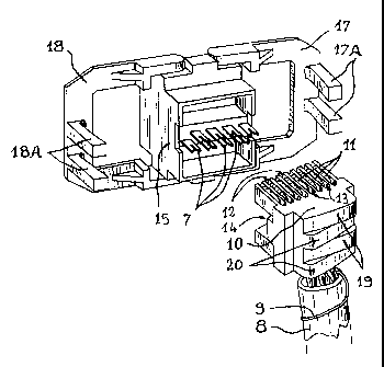
Figure 2 is a view in perspective of the rear of the socket, jaws
open and termination pusher separate but already equipped with the
strands of line of the input cable.
Figure 3 is a longitudinal section of the termination pusher of
5 Figure 2, showing the positioning of a strand of line.
Figure 4 is a view in the direction F of Figure 3.
Figure 5 is a view in perspective, with the jaws in the process of
closing on the rear of the termination pusher.
Figure 6 is a plan view corresponding to the position of Figure 5.
10 Figures 7 and 8 are views respectively similar to Figures 5 and 6,
with the jaws totally closed and therefore the termination pusher at the end
of stroke.
Figure 9 is a partial longitudinal section of the socket with the jaws
in position of complete closure, according to Figure 7.
15 DESCRIPTION OF PREFERRED EMBODIMENT
Referring again to the drawings, and now to all of Figures 2 to 4,
the rear part of this mural telephone or computer-related socket is
conventionally equipped with two parallel rows, each of four insulation-
displacing contacts 7, also known in internationally adopted language as
20 LD.C.'s.
As illustrated, these eight LD.C.'s 7 are all oriented in the same
direction, parallel to the axis of the socket and towards the rear thereof.
Each of these LD.C.'s 7 is intended to receive one of the strands of a four-
pair cable 8 which is to be connected to this socket. In the case of the
25 Figure shown here, this cable 8 arrives from below, in a bracket (not
shown). Reference 9 designates its conventional earth wire, or drain.
Reference 10 designates a termination pusher which can be
separated from the socket and intended to receive all the strands of line 11
before this pusher is plugged on the rear of the socket, in that case driving
30 each strand 11 in the respective insulation-displacing slot of the LD.C. 7

CA 02228900 1998-02-OS
4
associated therewith. This termination pusher is very particular, in that it
is totally symmetrical with respect to its median transverse plane Y, with
the result that the strands of line 11 can all be introduced equally well
from above or from below;.
5 Each strand of line 11 is introduced in an individual receiving
through tubing 13 which passes through the pusher 10 at right angles to
the plane Y, then is bent at right angles into a longitudinal receiving
tubing 12 which is parallel to plane Y; this configuration being totally
symmetrical with respect to plane Y, the strands 11 may be introduced in
10 the same way from above, as indicated in broken lines in Figure 3.
The pusher 10 presents an open mouth 14, at the bottom of which
the eight strands 11 are visible. This front mouth 14 is intended to be
plugged on a complementary male part 15 (Figure 2) located to the rear of
the socket, and which bears the eight LD.C.'s 7.
15 Transverse tubings 16 are provided, at the bottom of mouth 14 and
to the rear of the canals 13, to receive the free ends of the LD.C.'s, while
the strands 11 are driven by force in their respective receiving insulation-
displacing slots.
The socket comprises two L jaws 17 and 18 which, on closing on
20 each other, are intended to grip the rear of the pusher 10 which presents
receiving shapes 19 and 20 respectively, adapted thereto, provided to
cooperate with these jaws in order, by a powerful lever effect which will
be shown hereinafter, to plug the pusher 10 by force on its receiving part
15, and therefore to effect connection of the strands 11 on their respective
25 LC.D.'s 7.
Figures 5 and 6 show the two jaws 17, 18 in the process of closing.
By their end branches 17A and 18A, they push on the respective adapted
shapes 19 and 20 of the rear of the pusher 10. To that end, it suffices to
press laterally on these branches between the thumb and index finger of
3 0 one hand.

CA 02228900 1998-02-OS
5
At the end of stroke, the termination pusher is totally plugged in
and the strands 11 are all introduced in their respective LD.C.'s 7, as
shown in Figures 7 to 9, the connection in that case being effected.
It should be noted that the canals 13 for receiving the strands of
5 line 11 are located in a plane X which is parallel to the common plane Z
of the free end branches (17A, 18A) of the two jaws 17, 18, when the
latter are in the state of closure according to Figure 9.
As shown in Figure 9, each LD.C. 7 is conventionally connected,
in the body of the socket, to a respective elastic contact 21 of the open
10 mouth 22 of the Modular-Jack socket.
The socket which has just been described makes it possible to
receive, without bending the strands 11, a cable 8 arriving both from
below and from above. It may also receive, without problem, a cable 8
arriving either laterally or from the rear, but in that case the strands 11
15 will have to be bent at right angles, which is acceptable as mentioned
hereinabove.
It goes without saying that the invention is not limited to the
embodiment which has just been described. For example, each jaw 17, 18
might comprise one end branch 17A, 18A instead of two, as appears in the
20 Figures. This socket might also be constructed to receive a number of
telephone or computer lines different from four.

Representative Drawing
A single figure which represents the drawing illustrating the invention.
Administrative Status

2024-08-01:As part of the Next Generation Patents (NGP) transition, the Canadian Patents Database (CPD) now contains a more detailed Event History, which replicates the Event Log of our new back-office solution.

Please note that "Inactive:" events refers to events no longer in use in our new back-office solution.

For a clearer understanding of the status of the application/patent presented on this page, the site Disclaimer , as well as the definitions for Patent , Event History , Maintenance Fee  and Payment History  should be consulted.

Event History

Description Date
Inactive: IPC expired 2018-01-01
Inactive: IPC deactivated 2011-07-29
Time Limit for Reversal Expired 2008-02-05
Letter Sent 2007-02-05
Inactive: IPC from MCD 2006-03-12
Grant by Issuance 2005-06-28
Inactive: Cover page published 2005-06-27
Pre-grant 2005-04-11
Inactive: Final fee received 2005-04-11
Notice of Allowance is Issued 2004-12-30
Letter Sent 2004-12-30
Inactive: Approved for allowance (AFA) 2004-12-13
Amendment Received - Voluntary Amendment 2004-12-02
Inactive: S.30(2) Rules - Examiner requisition 2004-08-18
Amendment Received - Voluntary Amendment 2002-11-26
Letter Sent 2002-11-01
Request for Examination Received 2002-09-11
Request for Examination Requirements Determined Compliant 2002-09-11
All Requirements for Examination Determined Compliant 2002-09-11
Application Published (Open to Public Inspection) 1998-08-27
Inactive: First IPC assigned 1998-05-13
Classification Modified 1998-05-13
Inactive: IPC assigned 1998-05-13
Filing Requirements Determined Compliant 1998-04-29
Inactive: Filing certificate - No RFE (English) 1998-04-29
Application Received - Regular National 1998-04-28

Abandonment History

There is no abandonment history.

Maintenance Fee

The last payment was received on 2005-01-20

Note : If the full payment has not been received on or before the date indicated, a further fee may be required which may be one of the following

  • the reinstatement fee;
  • the late payment fee; or
  • additional fee to reverse deemed expiry.

Please refer to the CIPO Patent Fees web page to see all current fee amounts.

Owners on Record

Note: Records showing the ownership history in alphabetical order.

Current Owners on Record
POUYET S.A.
Past Owners on Record
YVES BOUDIN
Past Owners that do not appear in the "Owners on Record" listing will appear in other documentation within the application.
Documents

To view selected files, please enter reCAPTCHA code :


To view images, click a link in the Document Description column. To download the documents, select one or more checkboxes in the first column and then click the "Download Selected in PDF format (Zip Archive)" or the "Download Selected as Single PDF" button.

List of published and non-published patent-specific documents on the CPD .

If you have any difficulty accessing content, you can call the Client Service Centre at 1-866-997-1936 or send them an e-mail at CIPO Client Service Centre.


Document
Description 
Date
(yyyy-mm-dd) 
Number of pages   Size of Image (KB) 
Representative drawing 1998-09-10 1 14
Cover Page 1998-09-10 1 42
Abstract 1998-02-05 1 16
Description 1998-02-05 5 194
Drawings 1998-02-05 5 125
Claims 1998-02-05 1 35
Description 2004-12-02 5 194
Representative drawing 2005-06-01 1 17
Cover Page 2005-06-01 1 41
Courtesy - Certificate of registration (related document(s)) 1998-04-29 1 116
Filing Certificate (English) 1998-04-29 1 163
Reminder of maintenance fee due 1999-10-06 1 111
Reminder - Request for Examination 2002-10-08 1 115
Acknowledgement of Request for Examination 2002-11-01 1 176
Commissioner's Notice - Application Found Allowable 2004-12-30 1 161
Maintenance Fee Notice 2007-03-19 1 172
Correspondence 2005-04-11 1 31