Note: Descriptions are shown in the official language in which they were submitted.
CA 02229109 2005-07-27
METHODS OF COMPLETING A SUBTERRANEAN WELL
AND ASSOCIATED APPARATUS
BACKGROUND OF THE INVENTION
The present invention relates generally to operations wherein a
subterranean well is drilled and completed and, in a preferred embodiment
thereof, more particularly provides a method and associated apparatus for
drilling and completing a subterranean well.
It is well known in the art to drill an initial "parent" wellbore, and then
to drill at least one "lateral" wellbore, that is, a wellbore intersecting and
extending outwardly from the parent wellbore. Many methods and apparatus
for drilling the lateral wellbore and for completing the parent and lateral
wellbores have been conceived. For example, U.S. Patent No. 4,807,704 to
Hsu et al., discloses an apparatus and method wherein a whipstock is
positioned in a cemented and cased parent wellbore to guide milling and
drilling bits for forming the lateral wellbore, and the whipstock is then
replaced with a guide member attached via a sealed conduit to a dual string
packer. The guide member is utilized to guide a tubing string into the lateral
wellbore after the guide member has been properly positioned in the parent
wellbore and the packer has been set.
However, in keeping with the industry's efforts to provide advances in
the state of this art, there is a need for more efficient, economical,
convenient
and safe methods and apparatus. From the foregoing, it can be seen that it
would be quite desirable to provide a method and associated apparatus for
completing a subterranean well which is generally economical and efficient in
operation, and which provides increased functionality. It is accordingly an
object of the present invention to provide such a method and associated
apparatus. Other objects, features, and benefits of the present invention will
become apparent upon careful consideration of the description hereinbelow.
CA 02229109 1998-02-09
-2-
SUMMARY OF THE INVENTION
In carrying out the principles of the present invention, in accordance
with an embodiment thereof, a method is provided which enhances the
efficiency of operations wherein it is desired to complete a subterranean well
with multiple wellbore portions.
In broad terms, a method of completing a subterranean well having
first, second and third wellbore portions intersecting at a junction is
provided
by the present invention. The first wellbore portion extends to the earth's
surface, and the method includes the steps of providing a device having first,
second and third interconnected portals; conveying the device into the well;
and positioning the device at the junction.
Another method of completing a subterranean well having first, second
and third wellbore portions intersecting at a junction, and the first wellbore
portion e~;tending to the earth's surface is provided. The method includes the
steps of :providing a body having first and second interconnected portals;
conveying; the body into the well; positioning the body . at the junction;
providing a generally tubular structure having a third portal formed
therethrough; conveying the tubular structure into the well; inserting the
tubular structure into the body; and interconnecting the third portal to the
first and second portals.
Yet another method of completing a subterranean well is provided.
The method includes the steps of drilling first and second wellbore portions,
the second wellbore portion intersecting the first wellbore portion, and the
first wellbore portion extending to the earth's surface; providing a first
assembly including a packer and a whipstock releasably attached to the
packer; positioning the first assembly within the well with the whipstock
CA 02229109 1998-02-09
-3-
being disposed adjacent the intersection of the first and second wellbore
portions; setting the packer in the second wellbore portion; drilling a third
wellbore portion intersecting the first and second wellbore portions at a
junction, by deflecting a cutting tool off of the whipstock; providing a
second
assembly including a liner, a second packer, and a seal surface; positioning
the second assembly within the third wellbore portion; setting the second
packer within the third wellbore portion; providing a third assembly including
a third packer, a first tubular member attached to the third packer, and a
device attached to the first tubular member, the device including at least
first
and second interconnected portals; positioning the third assembly within the
well with the device at the junction; and setting the third packer in the
first
wellbore portion.
Apparatus operatively positionable within a subterranean well is also
provided by the present invention. The apparatus includes a device having
first, second and third interconnected portals formed therein, a first tubular
structure;. and a packer operatively connected at the first portal, and a
second
tubular structure and a sealing device operatively connected at the second
portal.
BRIEF DESCRIPTION OF THE DRAWINGS
FI(~. 1 is a schematic cross-sectional view of a subterranean well
wherein an initial portion of a first method of completing the well has been
performed, the method embodying principles of the present invention;
FI(~. 2 is a schematic cross-sectional view of the well of FIG. 1 wherein
further steps in the first method of completing the well have been performed;
FIGS. 3A - 3B are schematic cross-sectional views of the well of FIGS. 1
& 2 showing alternate configurations of apparatus utilized in the first
method,
the apparatus embodying principles of the present invention
CA 02229109 1998-02-09
-4-
FI(x. 4 is a schematic cross-sectional view of a subterranean well
wherein a.n initial portion of a second method of completing the well has been
performed, the method embodying principles of the present invention;
FI(IS. 5 - 8 are a schematic cross-sectional views of the well of FIG. 4,
wherein further steps in the second method of completing the well have been
performed;
FI(x. 9 is a schematic cross-sectional view of a subterranean well
wherein an initial portion of a third method of completing the well has been
performed, the method embodying principles of the present invention;
FI(xS. 10 & 11 are schematic cross-sectional views of the well of FIG. 9,
wherein further steps in the third method have been performed;
FI(I. 12 is a schematic cross-sectional view of the well of FIG. 9,
wherein alternate steps in the third method have been performed;
FI(~r. 13 is a schematic cross-sectional view of a subterranean well
wherein an initial portion of a fourth method of completing the well has been
performed, the method embodying principles of the present invention;
FIGS. 14 & 15 are a schematic cross-sectional views of the well of FIG.
13, wherein further steps in the fourth method have been performed;
FI(~. 16 is a schematic cross-sectional view of an apparatus which may
be utilized in the fourth method, the apparatus embodying principles of the
present invention;
FIGS. 17A & 17B are schematic cross-sectional views of alternate
configurations of an apparatus which may be utilized in the fourth method,
the apparatus embodying principles of the present invention;
FI(~r. 18 is a cross-sectional view of an apparatus which may be utilized
in the fourth method, the apparatus embodying principles of the present
invention;
CA 02229109 1998-02-09
_5_
FI(~. 19 is a schematic cross-sectional view of a fifth method of
completing a subterranean well, wherein steps of the method have been
performed, the method embodying principles of the present invention;
FI(~. 20 is a schematic cross-sectional view of a sixth method of
completing a subterranean well, wherein steps of the method have been
performed, the method embodying principles of the present invention;
FI(~. 21 is a schematic cross-sectional view of a seventh method of
completing a subterranean well, wherein steps of the method have been
performed, the method embodying principles of the present invention;
FI(~. 22 is a schematic cross-sectional view of an eighth method of
completing a subterranean well, wherein steps of the method have been
performed, the method embodying principles of the present invention;
FI(~. 23 is a cross-sectional view of an apparatus which may be utilized
in the eighth method, the apparatus embodying principles of the present
invention;
FI(~. 24 is a cross-sectional view of an apparatus which may be utilized
in the eighth method, the apparatus embodying principles of the present
invention; and
FI(~. 25 is a cross-sectional view of an apparatus which may be utilized
in the eighth method, the apparatus embodying principles of the present
invention;
DETAILED DESCRIPTION
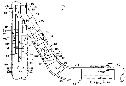
Schematically and representatively illustrated in FIG. 1 is a method 10
which ernbodies principles of the present invention. In the following
description of this embodiment of the invention, directional terms, such as
"above", "below", "upper", "lower", "upward", "downward", etc., are used for
convenience in referring to the accompanying drawings. It is to be understood
CA 02229109 1998-02-09
-6-
that the method 10 may be performed in orientations other than those
depicted. For example, a parent wellbore, although being depicted as
extending generally vertically, may actually be inclined, horizontal, or
otherwise oriented, and a lateral wellbore intersecting the parent wellbore,
although being depicted as extending generally horizontally, may actually be
inclined, vertical, etc. Additionally, more than one lateral wellbore may be
formed intersecting a single parent wellbore, according to the principles of
the
present irwention.
FICx. 1 shows a cross-section of a well after some initial steps of the
method 10 have been completed. An initial or parent wellbore 12 has been
drilled, cemented, and cased or lined, both above and below a desired point of
intersection 14 with a lateral wellbore 16 to be drilled later (the lateral
wellbore being shown in phantom lines in FIG. 1 as it is not yet drilled). The
point of intersection 14 refers not to a discreet geometric point in the well,
but
rather to an area where the parent and lateral wellbores 12, 16 intersect.
Casing 18 extends generally continuously through the upper and lower
portions c;0, 22 of the parent wellbore 12.
An assembly 24 is conveyed into the parent wellbore 12 and positioned
with respect to the point of intersection 14. The assembly 24 includes a
whipstocl~: 26 releasably attached to a packer 28. The packer 28 is set in the
casing 18 so that an upper inclined face 30 formed on the whipstock 26 faces
toward the desired lateral wellbore 16. In this respect, the whipstock 26 is
generally of conventional design and, although the inclined face 30 is
depicted
as being flat, it may actually have a curvature, etc. The whipstock 26 may be
attached to the packer 28 utilizing a conventional RATCH-LATCH'
connection 27 manufactured by, and available from, Halliburton Company of
Duncan, Oklahoma, or other such releasable connection.
CA 02229109 1998-02-09
_7_
The packer 28 has a tubular member 32 extending downwardly
therefrom.. The tubular member 32 may be a joint of tubing, a polished bore
receptacle, etc. Another packer 34 is set in the tubular member 32. Of course,
if the tubular member 32 is a polished bore receptacle, the packer 34 may be
replaced by a packing stack or other seals. Alternatively, the tubular member
32 may lie a mandrel of the packer 28, and the packer 34 may be seals
disposed therein. Thus, the packer 34 serves as a sealing device within, or
suspended from, the packer 28.
The packer 34 has a tubing string 36 extending downwardly therefrom.
The tubing string 36 includes a plug 38 and a sliding sleeve valve 40. The
plug 38 serves as a flow blocking device for preventing fluid flow through the
tubing sty°ing 36. The sliding sleeve valve 40 serves as a flow control
device
for selectively permitting fluid flow radially through the tubing string 36.
In
at least one embodiment of the present invention, which will be described in
more detail hereinbelow, the tubing string 36, with its associated plug 38 and
sliding sleeve valve 40, are not needed. However, where they are used in the
method 10, the sliding sleeve valve 40 may be a DURASLEEVE~ valve and
the plug 38 may be a MIRAGETM plug, both of which are manufactured by,
and available from, Halliburton Company. In general, the sliding sleeve valve
40 is used to selectively open and close a fluid communication path between
the tubing string 36 and the lower parent wellbore 22, for example, to test a
packer after setting it, and the plug 38 is used to block fluid communication
and physical access therebetween until it is desired to produce fluids from
the
lower parent wellbore.
With the assembly 24 positioned as shown in FIG. 1, and the packer 28
set in the casing 18, the lateral wellbore 16 may be drilled by, for example,
deflecting a milling tool off of the face 30 and milling through a portion 42
of
CA 02229109 1998-02-09
_g_
the casin;;, and then deflecting a drilling tool off of the face 30 to extend
the
wellbore '16 outwardly from the parent wellbore 12. FIG. 2 shows the lateral
wellbore .L6 after it has been drilled.
Rei:erring now additionally to FIG. 2, the method 10 is schematically
represented after additional steps have been performed. As described above,
the lateral wellbore 16 has been drilled and now intersects a formation 44
from which it is desired to produce fluids. The lower parent wellbore 22 also
intersects a formation 46 from which it is desired to produce fluids.
After the lateral wellbore 16 is drilled, all or a portion of it may be
cased or Lined and cemented, such as portion 48 of the lateral wellbore. In
the
representatively illustrated method 10, the portion 48 is lined and cemented
by positioning a liner 50 therein and setting packers, cement retainers, or
inflatable packers, etc., 52 straddling the portion 48. Cement may then be
flowed between the liner 50 and wellbore 16, and permitted to harden, to
thereby permit a lower portion 54 of the lateral wellbore 16 to be
conveniently
isolated from an upper portion 56 of the lateral wellbore.
Attached to the liner 50, and extending downwardly therefrom, a tubing
string 58 may be positioned in the lateral wellbore 16. The tubing string 58
includes a slotted liner 60, but it is to be understood that perforated
tubing,
screens, etc., may be utilized in place of the slotted liner as well. Note
that
the liner 50 and tubing string 58 may be positioned in the lateral wellbore 16
simultaneously if desired.
The whipstock 26 is retrieved from the well prior to further steps in the
method 11). The whipstock 26 is replaced with a hollow whipstock 66, similar
to the wh.ipstock 26, except that it has an axially extending bore 68 formed
therethrough. Note that the hollow whipstock bore 68 is preferably not sealed
at either end, and that it is circumscribed by a peripheral inclined surface
70.
CA 02229109 1998-02-09
_g_
The hollow whipstock 66 may be attached to the packer 28 utilizing a RATCH-
LATCH~ 27, or other, connection, so that the surface 70 is oriented to face
toward the lateral wellbore 16.
At this point, the method 10 may be continued in either of at least two
manners, depending largely upon whether it is desired to commingle fluids
produced from the formations 44, 46. The method 10 will first be described
hereinbelow for use where such commingling is desired, and then the method
will be described for use where commingling is not desired.
Two tubing strings 62, 64 are lowered simultaneously into the upper
parent wellbore 20 from the earth's surface. Referring additionally now to
FIG. 3A, it may be seen that the tubing strings 62, 64 are conveyed into the
parent wellbore 12 attached to a wye or "Y" connector 72 which is, in turn,
connected. to a packer 74 and a tubing string 76 extending to the earth's
surface. .Tote that flow from each of the tubing strings 62, 64 is commingled
in the wye connector 72. As will be more fully described hereinbelow, tubing
string 62 will be positioned in the lower parent wellbore 22 for production of
fluid (indi.cated by arrows 78) from the formation 46, and tubing string 64
will
be positioned in the lateral wellbore 16 for production of fluid (indicated by
arrows 80) from the formation 44. The commingled fluids (indicated by arrow
82) are, thus, produced through the tubing string 76 to the earth's surface.
The tubing strings 62, 64 are conveyed into the parent wellbore 12 with
both of them connected to the wye connector 72. Preferably, an axial length of
the tubing string 64 from the wye connector 72 to a relatively large item of
equipment included therein, such as a packer 84, is greater than the axial
length of the tubing string 62. In this manner, relatively large diameter
items
of equipment included in the tubing string 64 do not have to be contained side-
CA 02229109 1998-02-09
-10-
by-side with the tubing string 62 in the casing 18, thereby permitting such
relatively large diameter equipment to be utilized in the lateral wellbore 16.
The tubing string 64 includes the packer 84 and a tubing string 86
extending generally downwardly therefrom. The tubing string 86 includes a
flow blocking device or plug 88, a flow control device or sliding sleeve valve
90,
and a member 92. In general, the plug 88 and sliding sleeve valve 90 are
utilized for the same purposes as the plug 38 and sliding valve 40 of the
tubing string 36. As described above for the tubing string 36, the MIRAGETM
plug and DURASLEEVE~ sliding sleeve valve may be utilized for these items
of equipment. Thus, when the tubing strings 62, 64 are being initially
conveyed into the parent wellbore 12, the tubing string 62 is adjacent the
tubing string 64, but above the packer 84. Note that, as represented in FIG. 2
and for illustrative clarity, the tubing string 64 appears to have a larger
diameter than tubing string 62, but it is to be understood that either of the
tubing strings may be larger than, or the same diameter as, the other one of
them.
As the tubing strings 62, 64 are conveyed downward through the upper
parent wellbore 20, eventually they will arrive at the point of intersection
14.
The tubing string 64, being greater in length than tubing string 62, first
arrives at; the point of intersection 14. The member 92, attached to a lower
end of the tubing string 64, contacts the inclined surface 70 and is deflected
toward the lateral wellbore 16. The member 92 does not enter the bore 68 of
the hollow whipstock 66, since the member is configured in a manner that
excludes ;>uch entrance. For example, the member 92 may be a conventional
mule shoe having an outer diameter greater than the diameter of the bore 68.
It is to be understood that the member 92 and bore 68 may be otherwise
CA 02229109 1998-02-09
-11-
configured to exclude entrance of the tubing string 64 therein, without
departing from the principles of the present invention.
With the member 92 and, thus, the remainder of the tubing string 64
deflected toward the lateral wellbore 16, the tubing string 64 is further
lowered so that the packer 84 enters the liner 50. The tubing string 62 is, of
course, lowered simultaneously therewith, except that the tubing string 62 is
permitted to enter, and displace axially through, the bore 68. The hollow
whipstock: 66, therefore, acts as a selective deflection member, selecting the
tubing string 64 to be deflected over to the lateral wellbore 16, and
selecting
the tubing string 62 to be directed to the lower parent wellbore 22.
When the tubing string 62 has been conveyed into the lower parent
wellbore 22, it is then brought into sealing engagement with the sealing
device or packer 34. To accomplish such sealing engagement, the tubing
string 62 may be fitted with seals for engagement with a seal bore carried on
the sealing device 34, seals carried on the sealing device may engage a
polished outer diameter formed on the tubing string 62, or any of a number of
conventional methods may be used therefor. When the tubing string 62 is
sealingly engaged with the sealing device 34, the packer 84 and tubing string
86 are appropriately positioned within the lateral wellbore 16. Preferably,
the
tubing string 62 is also connected to the packer 34, such as by use of a
R,ATCH-L,ATCH~ connection therebetween.
Fluid pressure may then be applied to the tubing string 76 at the
earth's surface to set the packer 84 in the liner 50. As depicted in FIGS. 2 &
3A, and since the tubing strings 62, 64 are in fluid communication with each
other, the plug 38 and sliding sleeve valve 40 should be closed while the
packer 84 is being set (and, of course, the plug 88 and sliding sleeve valve
90
should be closed, also). Note that it is not necessary for the packer 84 to be
set
CA 02229109 1998-02-09
-12-
in the liner 50, but that the liner does provide a convenient location
therefor.
Alternatively, the packer 84 could be of the inflatable type and could be set
in
an unlined portion of the lateral wellbore 16.
With the packer 84 set in the lateral wellbore 16 and the tubing string
62 sealin~;ly engaging the packer 34, further fluid pressure may be applied to
the tubing string 76 to thereby set the packer 74 in the casing 18 in the
upper
parent wellbore 20. Again, the plugs 38, 88, and sliding sleeve valves 40, 90
should be closed while fluid pressure is applied to the tubing string 76 to
set
the packer 74. After the packer 74 has been set, fluids 78, 80 may be produced
from the formations 46, 44, respectively, to the earth's surface through the
tubing sty°ing 76 after opening desired ones of the plugs 38, 88 and/or
sliding
sleeve valves 40, 90. Note that the formations 44, 46 are both isolated from
each other and from an annulus 94 between the tubing string 76 and the
casing 18 extending to the earth's surface when packers 74, 84 are set and the
tubing string 62 is sealingly engaged with the sealing device 34. Accordingly,
the point of intersection 14 is also isolated from the lower parent wellbore
22,
lower lateral wellbore 54, and the annulus 94, and, thus, it is not necessary
to
line and cement the upper lateral wellbore 56, since any formation intersected
thereby is isolated from all other portions of the well.
Referring additionally now to FIG. 3B, the method 10 will now be
described for instances where it is desired to prevent commingling of the
fluids
78, 80. In place of the packer 74 shown in FIG. 3A, a dual string packer 96 is
utilized to permit separate fluid paths therethrough. The dual packer 96 is
conveyed into the parent wellbore 12 as a part of the tubing string 64. The
tubing string 62 is separately conveyed into the well, after the tubing string
64 is positioned within the lateral wellbore 16 and the packers 84, 96 have
been set a.s described hereinbelow.
CA 02229109 1998-02-09
- 13-
Alternatively, the tubing string 64 and a lower portion 62a of the tubing
string 62 may be conveyed into the wellbore 12, with the lower portion 62a
attached to the dual string packer 96. In that case, the remainder of the
tubing string 62 would be sealingly inserted into the dual string packer 96
(such as into a conventional scoop head thereof] after the tubing strings 64,
62a have entered their respective wellbores 16, 22 (as described above for the
tubing strings 62, 64 in the method 10 as depicted in FIG. 3A) and the dual
string packer has been set in the wellbore. The following further description
of the method 10 as depicted in FIG. 3B describes the tubing string 62,
including its lower portion 62a, as being separately conveyed into the well.
With the hollow whipstock 66 attached to the packer 28 and oriented as
described above, the tubing string 64, including the dual string packer 96,
packer 89:, and tubing string 86, is lowered into the upper parent wellbore
20.
Eventually, the member 92 contacts the hollow whipstock 66 and is deflected
toward the lateral wellbore 16. The tubing string 64 is lowered further, until
it is appropriately positioned within the lateral wellbore 16.
Fluid pressure is applied to the tubing string 64 at the earth's surface
to set thc~ packer 84 in the liner 50. Further fluid pressure may then be
applied to set the dual string packer 96 in the casing 18.
With the packers 84, 96 set, the tubing string 62 may then be conveyed
into the parent wellbore 12. As the tubing string 62 is lowered in the well,
it
eventually passes through a bore 98 of the dual string packer 96 in a
conventional manner, reaches the point of intersection 14, and is permitted to
pass through the bore 68 of the hollow whipstock 66. Thus, even when the
tubing string 62 is installed after the tubing string 64, the hollow whipstock
66 is still capable of serving as a selective deflection member.
CA 02229109 1998-02-09
- 14-
The tubing string 62 is further lowered into the lower parent wellbore
22, until it sealingly engages the sealing device 34 as described hereinabove.
The tubing string 62 is also preferably connected to the sealing device 34 as
described above. The tubing string 62 also sealingly engages the dual string
packer bore 98 in a conventional manner. Note, however, that, since the
tubing strings 62, 64 are not in fluid communication with each other, the plug
38 or sliding sleeve valve 40 need not be closed when the packer 84 is set
and,
in fact, the plug 38 or sliding sleeve valve 40 need not be included in the
tubing string 36. Indeed, it will be readily apparent to one of ordinary skill
in
the art that, if appropriately configured, instead of sealingly engaging the
sealing device 34, the tubing string 62 could directly sealingly engage the
tubular lr~ember 32, thereby eliminating the packer 34 and tubing string 36
altogether.
With the packers 84, 96 set in the liner 50 and casing 18, respectively,
and with the tubing string 62 sealingly engaging the packer 34 (or tubular
member 32) and packer bore 98, the fluids 78, 80 from the formations 46, 44,
respectively, may be flowed separately to the earth's surface after opening
desired ones of the plugs 38, 88 and/or sliding sleeve valves 40, 90. As with
the method 10 as described above in relation to FIG. 3A, the formations 44, 46
are both isolated from each other and from the annulus 94 between the tubing
strings 62, 64 and the casing 18 extending to the earth's surface above the
packer 96, and the point of intersection 14 is isolated from the lower parent
wellbore 22, lower lateral wellbore 54, and the annulus 94.
Thus has been described the method 10, which, in association with
uniquely configured apparatus, permits relatively large items of equipment,
such as packer 84 and tubing string 86, to be installed in the lateral
wellbore
16 whether the tubing strings 62, 64 are installed simultaneously or
CA 02229109 1998-02-09
-15-
separately, which requires few trips into the well, which is convenient,
economical, and efficient in its operation, and which permits automatic
selection of tubing strings to be deflected (or not deflected) into
appropriate
wellbores.
Rei:erring additionally now to FIGS. 4-8, a method 100 is
representatively and schematically illustrated, the method embodying
principles of the present invention. As depicted initially in FIG. 4, some
steps
of the method 100 have already been performed. A first wellbore portion 102
extending to the earth's surface has been drilled. A second wellbore portion
104, which intersects the first wellbore portion 102, has also been drilled.
A liner or casing 106 has been installed in the first and second wellbore
portions :102, 104, the casing extending internally through the junction or
intersection (indicated generally at 108) of the first and second wellbore
portions. Another liner or casing 110 has been installed in the second
wellbore portion 104, such as by attaching the liner 110 within the casing 106
by using ;~ conventional liner hanger 112. Attached to the liner 110 is a seal
surface 114, which may be, for example, a seal bore, a polished bore
receptacle, a packing stack or other seal, etc. The liner 110 and casing 106
are
cemented in place within the first and second wellbore portions 102, 104 as
shown, using conventional techniques.
An assembly 116 is then conveyed into the well adjacent the junction
108. The assembly 116 includes a packer 118 or other circumferential sealing
device, a tubular structure 120 (which may be a separate tubular member, a
mandrel of the packer, etc.) attached to the packer, a plug 122, a
conventional
nipple 124 having an orienting profile 126 formed therein, a seal surface 128
(which may be, for example, an external seal or polished seal surface, a
packing stack, a seal bore, etc.), and a whipstock 130 releasably attached to
CA 02229109 1998-02-09
-16-
the packer 118, for example, by utilizing a RATCH-LATCH. The whipstock
130 is positioned so that an inclined surface 132 formed thereon is adjacent
the junction 108 and faces radially toward a desired third wellbore portion
134.
The seal surface 128 sealingly engages the seal surface 114. The packer
118 is then set in the second wellbore portion 104 to anchor the assembly 116
therein, and to sealingly engage the assembly with the casing 106. An
opening 136 is milled through the casing 106 by deflecting a cutting tool (not
shown) off of the whipstock inclined surface 132. The third wellbore portion
134 is then drilled, so that the third wellbore portion extends outwardly from
the opening 136, the third wellbore portion, thus, intersecting the first and
second wellbore portions 102, 104 at the junction 108.
Another assembly 138 (see FI(1. 5) is then positioned in the well. The
assembly 138 includes a liner or casing 140, a valve 142 (for example, a
conventional valve used in cementing staged operations, etc.), a packer 144
(for example, an inflatable external casing packer), and a seal surface 146
(for
example, a seal bore, a polished bore receptacle, a packing stack, etc.). As
will
be more fully described hereinbelow, the assembly 138 may also include a
tubular drilling guide (not shown in FIG. 5, see FIG. 9) attached to the liner
140 and extending upwardly therefrom into the first wellbore portion 102. In
that case, a lower end of the tubular drilling guide may sealingly engage the
seal surface 146.
The assembly 138 is positioned within the well with the packer 144
being disposed within the third wellbore portion 134. The packer 144 is set in
the third wellbore portion 134 to thereby anchor and sealingly engage the
assembly 138 within the third wellbore portion. Such positioning of the
assembly 138 may be accomplished, for example, by suspending the assembly
CA 02229109 1998-02-09
-17-
from a running string 148 having a conventional liner running tool 150, and
conveying the running string and assembly into the well. The running string
148 may also include conventional cementing tools, such as a cup packer 152
and a scraper 154.
When the assembly 138 is appropriately positioned within the third
wellbore portion 134 and the packer 144 has been set, the valve 142 is opened
and cement (or other cementatious material) is pumped from the earth's
surface, through the running string 148, and into an annulus 156 radially
between i;he liner 140 and the third wellbore portion 134. The valve 142 is
closed and the cement is then permitted to harden in the annulus 156.
The running string 148 is then disengaged from the assembly 138, for
example, by disengaging the running tool 150 from the assembly. If a drilling
guide was attached to the assembly 138, the third wellbore portion 134 may
be extended by passing a cutting tool through the drilling guide, through the
liner 140, and drilling into the earth. When the drilling operations are
completed, the drilling guide may be disconnected from the assembly 138 and
retrieved to the earth's surface.
The whipstock 130 is then retrieved by detaching it from the packer 118
(see FIG. 6). The plug 122 is also retrieved from the well, thereby permitting
fluid communication axially through the remainder of the assembly 116, from
the interior of the liner 110 to the junction 108.
Another assembly 158 is conveyed into the well. The assembly 158
includes a multiple bore packer 160 (for example, a dual string packer), a
tubing string 162 connected to the packer and extending downwardly
therefrom, a housing 164 also connected to the packer and extending
downwardly therefrom, a tubular member 166 extending through a bore of the
packer and telescopingly received in the housing and releasably attached
CA 02229109 1998-02-09
-18-
thereto (for example, by shear pins 168) a seal surface 170 (for example, a
polished seal surface, a packing stack or other circumferential seal, etc.)
near
an upper end of the tubular member, and another seal surface 172 (for
example, a packing stack, a packer, a. polished seal surface, etc.) near a
lower
end of the tubular member. Preferably, the tubular member 166 includes a
previously deformed or bent portion 174, which is at least somewhat
straightened due to being laterally constrained within the housing 164.
The tubing string 162 includes a seal surface 176 (for example, a
polished seal surface, a packing stack or other circumferential seal, etc.)
and
an orienting surface 178 configured for cooperative engagement with the
orienting profile 126. The assembly 158 is positioned in the well, so that the
orienting surface 178 engages the orienting profile 126, thereby radially
orienting the assembly in the well with the housing 164 being disposed toward
the opening 136, and the seal surface 176 is sealingly engaged with the
tubular structure 120. The packer 160 is then set in the casing 106 in the
first
wellbore portion 102.
The tubular member 166 is released for displacement relative to the
housing 164 by, for example, applying sufficient downwardly directed force to
the tubular member to shear the shear pins 168. Means other than shear pins
for preventing premature displacement as are of course well known in the art
may also be used. The tubular member 166 is then extended outwardly (i.e.,
downwardly as viewed in FIG. 7) from the housing 164. If the tubular
member :166 includes the previously deformed portion 174, such outward
extension will cause the tubular member to deflect laterally toward the
opening 136, since the previously deformed portion will no longer be laterally
constrained by the housing 164. Alternatively, the housing 164 may be fitted
CA 02229109 1998-02-09
- 19-
with a device (such as rollers, etc., not shown in FIG. 7), which laterally
deflects the tubular member 166 as it is extended outwardly from the housing.
The tubular member 166 is then extended into the third wellbore
portion 134, until the seal surface 172 may sealingly engage the seal surface
146 or, alternatively, if the seal surface 172 is a packer, until the seal
surface
or packer 172 may be set in the assembly 138 as shown in FIG. 8. At this
point, the seal surface 170 sealingly engages the interior of the housing 164.
To flow fluids from the interior of the liner 110 and, thus, the second
wellbore
portion 104, to the earth's surface, a tubing string 180 having a seal surface
182 may be lowered into the well and the seal surface 182 sealingly engaged
with a bare of the packer 160 with which the tubing string 162 is in fluid
communication.
Nome that, with the seal surface 172 sealingly engaging the assembly
138, the seal surface 176 sealingly engaging the assembly 116, the seal
surface 170 sealingly engaging the housing 164, and the packer 160 set in the
casing 106, the junction 108 is isolated from fluid communication with the
first wellbore portion 102 above the packer 160, the second wellbore portion
104 below the assembly 116, and the third wellbore portion 134 below the
assembly 138. Also note that the third wellbore portion 134 below the
assembly 138 is in fluid communication with the interior of the tubular
member 166 (and with the interior of a tubing string 184 connected thereto
and extending to the earth's surface), and that the second wellbore portion
104
below the assembly 116 is in fluid communication with the interior of the
tubing string 162 and with the interior of the tubing string 180. Commingling
of fluids from the second and third wellbore portions 104, 134, if desired,
may
be accomplished by utilizing a single bore packer and wye block (see FIG. 3A
CA 02229109 1998-02-09
- 20 -
and accompanying written description) in place of the multiple bore packer
160.
Referring additionally now to FIGS. 9-12, a method 190 of completing a
subterranean well is representatively and schematically illustrated, the
method embodying principles of the present invention. As shown in FIG. 9,
some steps of the method 190 have been performed. A first wellbore portion
192 has been drilled from the earth's surface, and a second wellbore portion
194 has been drilled intersecting the first wellbore portion at an
intersection
or junction 196. A liner or casing 198 has been installed within the well,
extending internally through the junction 196. The casing 198 is cemented
within the first and second wellbore portions 192, 194.
An assembly 200 is then conveyed into the well. The assembly 200
includes a packer 202, a tubular structure 204 (which may be a separate
tubular member, a mandrel of the packer, etc.) attached to the packer, a seal
surface 206 (for example, a polished seal bore, a packing stack or other seal,
a
polished bore receptacle, etc.) attached to the tubular structure, a plug 216
preventing fluid flow through the tubular structure, and a whipstock 208
attached to the packer. As representatively illustrated, the whipstock 208 is
of the type which has a relatively easily milled central portion 210 for ease
of
access to the interior of the assembly 200, but it is to be understood that
the
whipstock may be otherwise configured without departing from the principles
of the present invention.
The assembly 200 is positioned within the well with the whipstock 208
being adjacent the junction 196. An inclined face 212 formed on the whipstock
208 faces radially toward a desired location for drilling a third wellbore
portion 214. The packer 202 is set in the second wellbore portion 194, thus
CA 02229109 1998-02-09
-21-
anchoring the assembly 200 within the well and sealingly engaging the second
wellbore portion.
An opening 218 is then milled through the casing 198 by deflecting a
cutting tool off of the whipstock inclined face 212. The third wellbore
portion
214 is drilled extending outwardly from the opening 218. At this point, only
an initial length of the third wellbore portion 214 is drilled, in order to
minimize damage to the junction 196 area of the well. As will be more fully
described hereinbelow, the third wellbore portion 214 is later extended
further
into the earth utilizing a removable tubular drilling guide 220.
An assembly 222 is then conveyed into the well. The assembly 222
includes a casing or liner 224, the tubular drilling guide 220, a packer 226
(for
example, a retrievable packer or retrievable liner hanger capable of anchoring
to and sealingly engaging the casing 198) attached to the drilling guide, a
packer 228 (for example, an external casing packer) attached to the liner 224,
a valve 230 (for example, a valve of the type used in staged cementing
operations), a seal surface 232 (for example, a polished seal surface, a
packing
stack or other seal, etc.) attached to the drilling guide, and a seal surface
234
(for example, a polished bore receptacle, a seal, etc.) attached to the liner
224.
The assembly 222 may be conveyed into the well utilizing a running
string 23Ei. The running string 236 may include a running tool 238 capable of
engaging the drilling guide 220, a tubing string 240 attached to the running
tool, and a sealing device 242 (for example, a packer, packing stack or other
seal, etc.). For convenience in later cementing operations, the running tool
238 may include ports 244 providing fluid communication between the interior
of the assembly 222 above the sealing device 242 and an annulus 246 between
the running string 236 and the first wellbore portion 192.
CA 02229109 1998-02-09
-22-
The assembly 222 is positioned in the well with the packer 228 being
disposed within the third well portion 214. The drilling guide 220 extends
internally through the junction 196, a portion thereof in the first wellbore
portion 192, and a portion in the third wellbore portion 214. The packer 228
is set in the third wellbore portion 2'14 to thus anchor the assembly 222 and
sealingly engage the third wellbore portion. The packer 226 is set in the
first
wellbore portion 192 to assist in anchoring the assembly 222 and to sealingly
engage the first wellbore portion.
To cement the liner 224 in place, the sealing device 242 is sealingly
engaged with the liner 224 and the valve 230 is opened. Cement or other
cementatious material may then be flowed through the running string 236
and into an annulus 248 between the liner 224 and the third wellbore portion
214. Rel~urns may be taken inward through the valve 230, through the
interior o:E' the assembly 222 above the sealing device 242, and through the
ports 244 into the annulus 246.
When the cementing operations have been completed, the running tool
238 is detached from the drilling guide 220 and the running string 236 is
retrieved from the well. As shown in FIG. 10, the liner 224 has been
cemented in place and the running string 236 has been removed. Note that
the drilling guide 220 forms a smooth, generally continuous transition from
the first wellbore portion 192 to the third wellbore portion 214, thus
permitting drill bits, other cutting tools, and other equipment to pass from
the
first wellbore portion into the third wellbore portion without deflecting off
of
the whipstock 208 and without damaging any of the well surrounding the
junction 196. Additionally, note that equipment may pass easily between the
first and third wellbore portions 192, 214 through the drilling guide 220
CA 02229109 1998-02-09
-23-
without regard to the size or shape of the equipment, provided that the
equipment will fit within the interior of the drilling guide.
The third wellbore portion 214 is then extended by drilling further into
the earth, for example, to intersect a. formation (not shown) from which it is
desired to produce fluids. In order to extend the third wellbore portion 214,
cutting tools are passed through the assembly 222 as described above. When
the drilling operations are completed, the drilling guide 220 is detached from
the liner 224 and retrieved from the well. To retrieve the drilling guide 220,
a
running tool, such as the running tool 238, is engaged with the drilling
guide,
the packer 226 is released from its engagement with the first wellbore portion
192, the seal surfaces 232, 234 are disengaged, and the drilling guide is
raised
to the earth's surface.
In ;gin alternative method of retrieving the drilling guide 220, it may be
severed from the remainder of the assembly 222 by, for example, mechanically
or chemically cutting the drilling guide within the third wellbore portion
214.
In that case, the drilling guide 220 may be an extension or a part of the
liner
224 and may be sealingly coupled thereto by, for example, a threaded
connection, etc., instead of utilizing the seal surfaces 232, 234 at a
predetermined separation point. FIG. 11 shows the drilling guide 220
removed from the well.
An opening 250 is then created axially through the whipstock 208,
removing the central portion 210, and leaving only a peripheral inclined
surface 252 outwardly surrounding the opening 250. This removal can
accomplished be by way of milling, mechanical removal, chemical removal, or
by other methods that are well known in the art. In certain applications, the
opening 250 may already be in the whipstock 208 at the time it is first
positioned in the wellbore. The plug 216 is removed from the tubular
CA 02229109 1998-02-09
-24-
structure 204, so that fluid flow is permitted through the assembly 200. At
this point, the well of the method 190 is similar in many respects to the well
of
the method 10 representatively illustrated in FIG. 2. Tubing strings 254, 256
may be conveniently installed for conducting fluids from the second and third
wellbore portions 194, 214 to the first wellbore portion 192, utilizing any of
the methods described hereinabove. For example, the tubing string 254,
including a seal or sealing device 258, and the tubing string 256, including a
seal or sealing device 260 and a deflection member 262 near a lower end
thereof, may be attached to a packer (such as the packer 74 or 96 shown in
FIGS. 3A & 3B) and lowered simultaneously into the well.
With the tubing string 256 longer than the tubing string 254, the
deflection member 262 first contacts the peripheral surface 252 and deflects
the tubing string 256 to pass through the opening 218 (the deflection member
not being permitted to pass through the opening 250) and into the third
wellbore portion 214. As the tubing strings 254, 256 are further lowered, the
tubing string 254 eventually passes through the whipstock opening 250. The
sealing devices 258, 260 are then sealingly engaged with the tubular structure
204 and liner 224, respectively, and the packer attached the tubing strings is
set in the first wellbore portion 192. Alternatively, one of the tubing
strings
254, 256 may be installed in the well before the other one.
FIG. 12 representatively illustrates another alternative installation of
the tubing strings 254, 256, wherein the tubing string 256 does not extend
into the third wellbore portion 214. The tubing string 256 is shorter than the
tubing string 254 and does not include the deflection member 262 or sealing
device 260. For this reason, and if it is desired, the whipstock 208, instead
of
being milled through before installation of the tubing strings 254, 256, may
be
removed from the well after being detached from the packer 202. The
CA 02229109 1998-02-09
-25-
whipstock 208 is shown in FIG. 12, since it may be desired in the future to
install a tubing string or other equipment in the third wellbore portion 214.
Flow control devices, such as valves, plugs, etc., may be included in the
tubing strings 254, 256, to permit selective fluid communication between the
second and third wellbore portions 194, 214, and the first wellbore portion
192
through the tubing strings. For' example, a valve 264, such as a
DUR,ASLEEVE~ valve, may be installed in the tubing string 254, so that the
tubing string 254 may be placed in fluid communication with the second
wellbore portion 194 and with the third wellbore portion 214 when the valve is
opened.
Note that the alternative installation of the tubing strings 254, 256
shown in FIG. 12 is substantially different from the installation of the
tubing
strings shown in FIG. 11 in the manner in which the area of the well
surrounding the junction 196 is in fluid isolation or communication with the
wellbore portions 192, 194, 214. In the installation shown in FIG. 11, it will
be readily apparent that the area of the well surrounding the junction 196 is
isolated from fluid communication with the third wellbore portion 214 below
the sealing device 260, isolated from fluid communication with the second
wellbore portion 194 below the sealing device 258, and isolated from fluid
communication with the first wellbore portion 192 above the packer 76 or 94
(see FIG. 3A & 3B). In contrast, in the installation shown in FIG. 12, it will
be readily apparent that the area of the well surrounding the junction 196 is
substantially isolated from fluid communication with the first and second
wellbore portions 192, 194, but is in fluid communication with the third
wellbore portion 214. Thus, the installation shown in FIG. 12 does not seal
the junction 196 off from the third wellbore portion 214, and should be used
where such lack of sealing is acceptable.
CA 02229109 1998-02-09
-26-
Referring additionally now to FIGS. 13-15, a method 270 of completing
a subterranean well is representatively and schematically illustrated, the
method embodying principles of the present invention. As shown in FIG. 13,
some steps of the method 270 have already been performed. A first wellbore
portion 272 has been drilled from the earth's surface, and a second wellbore
portion 274 has been drilled intersecting the first wellbore portion at an
intersection or junction 276. A liner or casing 278 has been installed within
the well, extending internally through the junction 276. The casing 278 is
cemented within the first and second wellbore portions 272, 274.
An assembly 280 is then conveyed into the well. The assembly 280
includes a packer 282, a tubular structure 284 (which may be a separate
tubular member, a mandrel of the packer, etc.) attached to the packer, a seal
surface 286 (for example, a polished seal bore, a packing stack or other seal,
a
polished bore receptacle, etc.) attached to the tubular structure, and a
whipstock 288 attached to the packer. As representatively illustrated, the
whipstock 288 is similar to the whipstock 208 described previously and has a
relatively easily milled central portion for ease of access to the interior of
the
assembly 280, but it is to be understood that the whipstock may be otherwise
configured without departing from the principles of the present invention. As
shown in FIG. 13, the whipstock 288 central portion has been milled through,
leaving an opening 290 therethrough.
The assembly 280 has been positioned within the well with the
whipstock 288 being adjacent the junction 276. An inclined face formed on the
whipstock 288 faced radially toward a desired location for drilling a third
wellbore portion 292 before the whipstock was milled through. The packer
282 was set in the second wellbore portion 274, thus anchoring the assembly
280 within the well and sealingly engaging the second wellbore portion.
CA 02229109 1998-02-09
-27-
An opening 294 was then milled through the casing 278 by deflecting a
cutting tool off of the whipstock inclined face. The third wellbore portion
292
was drilled extending outwardly from the opening 294. After drilling the third
wellbore portion 292, the whipstock 288 was milled through, forming the
opening 290 and leaving a peripheral inclined face 296 outwardly surrounding
the opening 290.
An assembly 298 is then conveyed into the well. The assembly 298
includes a casing or liner 300, a valve 302 (for example, a valve of the type
used in staged cementing operations), a packer 304 (for example, an external
casing packer), a seal surface 306 (for. example, a packing stack or other
seal,
a seal bore, a polished bore receptacle, etc.), a generally tubular member 308
having a window or aperture 310 formed through a sidewall portion thereof,
and another packer 312 attached to the tubular member. The assembly 298
may be conveyed into the well suspended from a running string 314, similar to
the running string 236 with running tool 238 previously described. In a
unique aspect of the present invention, the running string 314 may also
include a device 316 configured for locating the junction 276 so that the
aperture 310 may be aligned with the opening 290, or with the second
wellbore portion 274.
Note that the liner 300, valve 302, packer 304, and seal surface 306
may be separately conveyed into the well, similar to the manner in which the
assembly 138 is conveyed and positioned in the method 100 using the running
string 148. In that case, the running string 314 may convey the tubular
member 308, packer 312, and a sealing device 318 (for example, an inflatable
packer, a packing stack or other seal, etc.) into the well after the liner has
been cemented into the third well portion 292 as previously described. The
sealing device 318 may sealingly engage the seal surface 306, for example, if
CA 02229109 1998-02-09
-28-
the sealing device is an inflatable packer, by opening a valve 320 positioned
on
the running string 314 between two sealing devices 322 straddling the sealing
device 318, and applying fluid pressure to the running string to inflate the
sealing device 318.
As representatively illustrated in FIG. 13, the locating device 316 is a
hook-shaped member pivotably secured to the running string 314. The device
316 extends outward through the aperture 310 when the tubular member 308
is conveyed into the well. As the device 316 passes by the whipstock opening
290, the device is permitted to engage the whipstock 288 adjacent its
peripheral surface 296, thereby aligning the aperture 310 with the opening
290. Of course, the device 316 may have many forms, and may be otherwise
attached without departing from the principles of the present invention. For
example, the device 316 may be attached to the tubular member 308 instead
of the running string 314, the device may be shaped so that it cooperatively
engages another portion of the whipstock 288 or another portion of the
assembly 280, etc. Where the whipstock 288 is of the type releasably attached
to the packer 282, the whipstock may be detached from the packer prior to
installing the tubular member 308, in which case the opening 290 may not
have been formed through the whipstock and the device 316 may engage the
packer 282 instead of the whipstock. Also note that a seal (not shown in FIG.
13, see FIG. 20) may be positioned on the tubular member 308 circumscribing
the aperture 310 and, when the device 316 has located the opening 290, the
seal may sealingly engage the peripheral surface 296.
With the aperture 310 aligned with the opening 290, that is, facing
toward the second wellbore portion 274, the packer 312 is set in the first
wellbore portion 272. At this point., the tubular member 308 is sealingly
engaged with the liner 300, and the tubular member extends through the
CA 02229109 1998-02-09
-29-
junction 276. Of course, where the tubular member 308 is conveyed into the
well separate from the liner 300, it may be preferable to sealingly engage the
tubular member and liner before setting the packer 312. The packer 304 was
set in the third wellbore portion 292 prior to cementing the liner 300
therein.
The running string 314 is then detached from the tubular member 308
and removed from the well. FIG. 14 shows the well after the running string
314 has been removed therefrom. At this point, an unobstructed path is
presented from the first wellbore portion 272, through the interior of the
assembly 286, and to the second wellbore portion 274. The junction 276 is in
fluid communication with the first, second and third wellbore portions 272,
274, 292.
An assembly 324 is then conveyed into the well (see FIG. 15). The
assembly 324 includes a tubular member 326, a packer 328, a sealing device
330 configured for sealing engagement with the tubular member 308, a
sealing device 332 configured for se;~ling engagement with the seal surface
286, and a flow diverter device 334 attached to the packer 328. The assembly
324 is conveyed into the well utilizing a tubing string 336 extending to the
earth's surface.
The assembly 324 is positioned within the well with the tubular
member 326 extending through the aperture 310, the sealing device 332
sealingly engaging the seal surface 286, and the sealing device 330 sealingly
engaging a seal surface 338 attached to the tubular member 308. The packer
328 is then set in the first wellbore portion 272 to anchor the assembly 324
in
place.
At this point, the second wellbore portion 274 is in fluid communication
with the interior of the tubing string 336, through the tubular member 326,
and via a generally axially extending fluid passage 340 formed through the
CA 02229109 1998-02-09
-30-
flow diverter 334. The third wellbore portion 292 below the liner 300 is in
fluid communication with an annulus 342 between the tubing string 336 and
the first wellbore portion 272, through the interior of the assembly 298,
through the tubular member 308, and via a series of ports 344 formed
generally radially through a sidewall portion of the flow diverter 334. In
this
manner, fluid from the third wellbore portion 292 may be produced via the
annulus 342 to the earth's surface while fluid from the second wellbore
portion
274 is produced via the interior of the tubing string 336 to the earth's
surface.
Alternatively, fluid may be injected from the earth's surface via the annulus
342 or the tubing string 336, while fluid is produced via the other. In that
case, preferably the fluid to be injected is flowed from the earth's surface
via
the annulus 342.
Referring additionally now to FIG. 16, an alternate flow diverter 346 is
representatively and schematically illustrated, the flow diverter embodying
principles of the present invention. The flow diverter 346 may be used in
place of the flow diverter 334 shown in FIG. 15.
The flow diverter 346 includes a centrally disposed axial flow passage
348, a series of peripherally disposed, circumferentially spaced apart, and
axially extending fluid passages 350, and a series of circumferentially spaced
apart and generally radially extending ports 352. A retrievable plug 354
initially prevents fluid flow axially through the central flow passage 348.
When installed in place of the flow diverter 334 in the method 270, the
peripheral fluid passages 350 permit fluid communication between the
interior of the tubular member 308 (and, thus, with the third wellbore portion
292) and the interior of the tubing string 336. The radial ports 352 permit
fluid communication between the interior of the tubular member 326 (and,
thus, with the second wellbore portion 274) and the annulus 342. If it is
CA 02229109 1998-02-09
-31-
desired to commingle these flows, or otherwise to provide fluid communication
between the fluid passages 350 and the radial ports 352, the plug 354 may be
removed from the axial flow passage 348. This may, for example, be desired
to provide circulation between the annulus 342 and the tubing string 336, for
example, to kill the well, etc. The plug 354 may later be replaced in the
axial
flow passage 348, if desired. Another reason for removing the plug 354 may
be to provide unrestricted access to l;he second wellbore portion 274 through
the tubular member 326, for example., for remedial operations therein.
If it is desired to remove the plug 354 without permitting fluid
communication between the flow passages 350 and the radial ports 352,
another flow diverter 356 (see FIG. 19) embodying principles of the present
invention may be used in place of the flow diverter 346. The flow diverter 356
includes an internal sleeve 358 and circumferential seals 360 axially
straddling its radial ports 362 (only one of which is visible in FIG. 19).
When
its plug 364 is removed from its central axial flow passage 366, the sleeve
358
may be displaced so that the sleeve blocks fluid communication between the
central flow passage and the radial ports 362. The sleeve 358 may be so
displaced, for example, by utilizing a conventional shifting tool, or the
sleeve
may be releasably attached to the plug 364, so that, as the plug is removed
from the central flow passage 366, the sleeve is displaced therewith, until
the
sleeve blocks flow through the radial ports 362, at which time the plug is
released from the sleeve.
Referring additionally now to :E'IGS. 17A & 17B, another flow diverter
368 is representatively and schematically illustrated, the flow diverter
embodying principles of the present invention. As with the flow diverter 346,
the flow diverter 368 shown in FIGS. 17A & 17B may be utilized in place of
the flow diverter 334 in the method 270. The flow diverter 368 includes an
CA 02229109 1998-02-09
- 32 -
outer housing 370 and a generally tubular sleeve 372 axially slidingly
disposed within the housing.
The housing 370 includes a series of circumferentially spaced apart and
generally radially extending ports 374 providing fluid communication through
a sidewall portion of the housing. Fluid flow through the ports 374 is
selectively permitted or prevented, depending upon the position of the sleeve
372 within the housing 370. As shown in FIG. 17A, fluid flow is permitted
through the ports 374, due to a generally radially extending port 376 formed
through the sleeve 372 being in fluid communication therewith. Such fluid
communication is permitted since both the housing ports 374 and the sleeve
port 376 are axially straddled by two seals 378 which sealingly engage the
exterior of the sleeve 372 and the interior of the housing 370. As shown in
FIG. 17B, fluid flow is prevented through the ports 374, the sleeve 372 having
been axially displaced so that the port 376 is no longer straddled by the
seals
378.
The sleeve 372 further includes a generally axially extending flow
passage 380. The flow passage 380 permits fluid communication between the
interior of the tubing string 336 and the interior of the tubular member 308
(and, thus, with the third wellbore portion 292). A circumferential seal 382
isolates the flow passage 380 from fluid communication with an axially
extending central flow passage 384 formed through the sleeve 372. A
conventional latching profile 386 is formed internally on the sleeve 372 and
permits displacement of the sleeve 372 by, for example, latching a shifting
tool
thereto.
A plug 388 may be initially installed in the central flow passage 384 to
prevent fluid flow therethrough. Note that the sleeve 372 in the flow diverter
368 may be displaced without removing the plug 388, since the shifting profile
CA 02229109 1998-02-09
-33-
386 is positioned above the plug 388. Removal of the plug 388 permits fluid
communication between the interior of the tubular member 326 (and, thus,
the second wellbore portion 274) and t;he interior of the tubing string 336.
Referring additionally now to :FIG. 18, a flow diverter 390 embodying
principles of the present invention is representatively and schematically
illustrated. The flow diverter 390 may be utilized in the method 270 in place
of the flow diverter 334. As representatively illustrated, the flow diverter
390
may be positioned in the assembly 324 between the packer 328 and the
tubular member 326. In this manner, the annulus 342 is in fluid
communication with an annulus 392 between the tubing string 336 and the
interior of the packer 328.
The flow diverter 390 includes a generally tubular upper housing 394
coaxially attached to a generally tubular lower housing 396. In the method
270, the upper housing 394 is attached to the packer 328 and to the tubing
string 336, and the lower housing is attached to the tubular member 326. A
generally tubular sleeve 398 is axially reciprocably disposed within the upper
and lower housings 394, 396.
The upper housing 394 includes a central axially extending flow
passage 400 formed therethrough, within which the sleeve 398 is slidingly
disposed. A series of circumferentially spaced apart and axially extending
peripheral flow passages 402 are formed through the upper housing 394. The
flow passages 402 permit fluid communication between the annulus 392 and
an annulus 404 radially between the lower housing 396 and the sleeve 398
and axially between the upper housing 394 and a radially enlarged portion
406 formed on the sleeve. The central flow passage 400 permits fluid
communication between the interior of the tubing string 336 and the interior
of the tubular member 326 (and, thus, the second well portion 274). Of course,
CA 02229109 1998-02-09
-34-
a plug may be disposed within the upper housing 394, lower housing 396, or
sleeve 398 if desired to prevent such fluid communication.
FIG. 18 shows the sleeve 398 in alternate positions. With the sleeve
398 in an upwardly displaced position, a seal 408 carried on the radially
enlarged portion 406 sealingly engages a seal bore 410 formed internally on
the lower housing 396. Another seal 412 carried internally on the upper
housing 394 sealingly engages the exterior of the sleeve 398. Thus, with the
sleeve 398 in its upwardly disposed position, fluid flow is prevented through
the flow passages 402.
With the sleeve 398 in its downwardly displaced position, the seal 408
no longer sealingly engages the bore 410, and fluid communication is
permitted between the flow passages 402 and a series of ports 414 formed
radially through the lower housing 396. Thus, fluid (indicated by arrow 416)
may be flowed from the annulus 3f)2 through the ports 414 and into the
interior of the tubular member 308 (and, thus, into the third wellbore portion
292) when the sleeve 398 is in its downwardly disposed position.
A seal 418 carried internally within the lower housing 396 sealingly
engages the exterior of the sleeve 398. An annulus 420 radially between the
sleeve 398 and the interior of the lower housing 396 and axially between the
enlarged portion 406 and a shoulder 422 formed internally on the lower
housing 396 is in fluid communication with the exterior of the flow diverter
390 via the ports 414 (when the sleeve is in its upwardly displaced position)
and a series of ports 424 formed radially through the lower housing 396 (at
all
times). When the fluid pressure in the annulus 404 exceeds the fluid pressure
in the annulus 420, the sleeve 398 is biased downwardly. Thus, the flow
diverter 390 may be installed in the assembly 324 and conveyed into the well
with the sleeve 398 in its upwardly disposed position, and then, after the
CA 02229109 1998-02-09
-35-
assembly has been installed as previously described in the method 270, fluid
pressure may be applied to the annulus 342 at the earth's surface, thereby
biasing the sleeve 398 to displace downwardly and permit fluid
communication between the annulus 392 and the ports 414. The sleeve 398
also has latching profiles 426 formed internally thereon to permit
displacement of the sleeve by, for example, latching a shifting tool therein
in a
conventional manner.
Referring additionally now to FIG. 19, a method 430 of completing a
subterranean well embodying principles of the present invention is
representatively and schematically illustrated. The method 430 is somewhat
similar to the method 270 and, therefore, elements shown in FIG. 19 which
are similar to those previously described are indicated using the same
reference numerals, with an added suffix "b". In the method 430, after the
assembly 298b, including the tubular member 308b, is installed in the well as
previously described, an assembly 432 is conveyed into the well instead of the
assembly 324 in the method 270.
The assembly 432 includes a tubular member 434, the flow diverter
356, the sealing device 330b, a sealing device 436 (for example, a packing
stack, packer, a seal, a polished seal surface, etc.), a valve 438 (for
example, a
DURASLEEVE~ valve), and a plug 9:40. The assembly 432 is conveyed into
the well suspended from the tubing string 336b. The sealing device 330b
sealingly engages the seal surface 338b, and the sealing device 436 sealingly
engages a seal surface 442 (for example, a polished seal bore, a packing stack
or other seal, etc.) attached to a casing or liner 444 previously installed in
the
second well portion 274b. The valve 438 may then be utilized to selectively
permit or prevent fluid flow between t;he second wellbore portion 274b and the
interior of the tubular member 434, and the plug 440 may be removed to
CA 02229109 1998-02-09
-36-
permit unrestricted access to the second wellbore portion (provided, of
course,
that the plug 364 of the flow diverter 356 has also been removed).
It is to be understood that others of the flow diverters 334, 390, 368,
346 may be utilized in place of the flow diverter 356 in the method 430
without departing from the principles of the present invention. Note that the
method 430 does not utilize the packer 328 of the method 270, but that the
method 430 may utilize the packer 3 28 without departing from the principles
of the present invention. Preferably, an anchoring device is provided with the
assembly 432 to secure it in its position in the well as shown in FIG. 19, and
for that purpose, the sealing device 436 may be a packer if the packer 328 is
not utilized.
Referring additionally now to FIG. 20, a method 450 of completing a
subterranean well embodying principles of the present invention is
representatively and schematically illustrated. The method 450 is somewhat
similar to the method 270 and, therefore, elements shown in FIG. 20 which
are similar to those previously described are indicated using the same
reference numerals, with an added suffix "c". In the method 450, after the
assembly 298c, including the tubular member 308c, is installed in the well as
previously described, an assembly 452 is conveyed into the well instead of the
assembly 324 in the method 270.
In addition, the liner 300c, packer 304c, valve 302c, and tubular
member 308c are arranged somewhat; differently in the third wellbore portion
292c in the method 450. Instead of the liner 300c being cemented within the
wellbore portion 292c below the packer 302c, the tubular member 308c is
cemented within the first and third wellbore portions 272c, 292c, with the
cement or other cementatious material extending generally between the
packers 312c and 304c. In this manner, the area of the well surrounding the
CA 02229109 1998-02-09
-37-
junction 276c is isolated from fluid communication with the first, second and
third wellbore portions 272c, 274c, 292c. The cementatious material may also
surround the whipstock 288c in the second wellbore portion 274c. In order to
prevent the cementatious material from entering the interior of the tubular
member 308c and the whipstock opening 290c, a seal 458 may be provided for
sealing engagement with the peripheral surface 296c and with the tubular
member 308c circumscribing the aperture 310c. The seal 458 may be carried
on the peripheral surface 296c, or it may be carried on the tubular member
308c. Alternatively, the cementatious material may be permitted to flow into
the opening 290c and aperture 310c, and then later removed before installing
the assembly 452.
The assembly 452 includes the packer 328c, the sealing device 330c, a
valve 454 (for example, a DURASLEEVE~ valve), a tubular member 456, the
sealing device 332c, the valve 438c, and the plug 440c. After the tubular
member 308c has been installed as previously described, the assembly is
conveyed into the well suspended from the tubing string 336c. The sealing
device 330c sealingly engages the seal surface 338c, and the sealing device
332c sealingly engages the seal surface 286c. The packer 328c is then set to
secure the assembly 452 within the well.
Utilizing the valves 454, 438c, and the plug 440c, fluid communication
between the interior of the tubing string 336c and each of the second and
third
wellbore portions 274c, 292c may be conveniently and independently
controlled. Fluid communication between the interior of the tubing string
336c and the second wellbore portion 274c may be established by opening the
valve 438c and/or by removing the plug 440c. Fluid communication between
the interior of the tubing string 336c and the third wellbore portion 292c may
be established by opening the valve 4 54. Of course, both valves 454, 438c may
CA 02229109 1998-02-09
-38-
be opened, or the valve 454 may be opened and the plug 440c removed, to
thereby permit fluid communication between the second and third wellbore
portions 274c, 292c and the interior of the tubing string 336c at the same
time.
Referring additionally now to FIG. 21, a method 460 of completing a
subterranean well embodying principles of the present invention is
representatively and schematically illustrated. The method 460 is in some
respects similar to the method 10 as representatively illustrated in FIG. 2,
and, therefore, elements shown in FIG. 21 which are similar to those
previously described are indicated in FIG. 21 using the same reference
numerals, with an added suffix "d".
After the parent wellbore 12d and lateral wellbore 16d have been
drilled, the casing 18d installed, and the tubular string 58d installed in the
lateral wellbore (and the whipstock 66, packer 28, etc., removed from the
lower parent wellbore 22d), an assembly 462 is conveyed into the well. The
assembly 462 includes a packer 464 a tubular string 466 attached to the
packer, a valve 468 (for example, a DURASLEEVE~ valve), another packer
470, another valve 472 (for example, a DURASLEEVE~ valve), and a plug
474. The assembly 462 may be conveyed into the well suspended from a
tubing string 476 extending to the earth's surface.
The assembly 462 is positioned within the well with the packer 464
disposed in the upper parent wellbore 20d and the packer 470 disposed in the
lower parent wellbore 22d, and the tubular string 466 extending through the
point of intersection or junction 14d. The valve 468 is positioned axially
between the packers 464, 470, and the valve 472 and plug 474 are positioned
below the packer 470 in the lower parent wellbore 22d. The packer 464 is set
CA 02229109 1998-02-09
-39-
in the upper parent wellbore 20d and the packer 470 is set in the lower parent
wellbore 22d.
Fluid 80d from the formation 44d may be permitted to flow into the
interior of the tubing string 476 by opening the valve 468, or fluid 78d from
the formation 46d may be permitted to flow into the interior of the tubing
string 476 by opening the valve 472 or removing the plug 474, or both of the
valves 468, 472 may be opened to establish fluid communication between the
interior of the tubing string and both of the lower parent wellbore 22d and
the
lateral wellbore 16d. Removal of the plug 474 permits physical access to the
lower parent wellbore 22d.
It will be readily apparent to one of ordinary skill in the art that where
flow control devices, such as valves 40, 90, 438, 438c, 472 and plugs 38, 88,
440, 440c, 474 are used to control access to, and/or control fluid
communication with, a portion of a wellbore in the various methods described
herein, other combinations or arrangement of flow control devices may be
utilized. For example, in the method 450 representatively illustrated in FIG.
20, in order to establish fluid communication between the interior of the
tubular member 456 and the second wellbore portion 274c below the packer
282c, the plug 440c may be removed, and it is not necessary to also provide
the valve 438c in the assembly 452. Therefore, it is to be understood that, in
the methods described herein, substitutions, modifications, additions,
deletions, etc. may be made to the flow control devices described as being
utilized therewith, without departing from the principles of the present
rove ntion.
Again referring to FIG. 21, the tubular string 466 may be attached to
the packer 470 by a releasable attachment member 478 (for example, a
RATCH-LATCH~). In this manner, i;he tubing string 476, packer 464, valve
CA 02229109 1998-02-09
-40-
468, and tubular string 466 may be removed from the well, leaving the packer
470, valve 472, and plug 474 in the lower parent wellbore 22d, and thereby
permitting enhanced physical access to the lateral wellbore 16d for remedial
operations therein, etc. In this case, it will be readily appreciated that the
whipstock 66 could be previously or subsequently attached to the packer 470.
It will be further appreciated that the packer 470, valve 472, and plug 474
may correspond to the packer 28, valve 40, and plug 38 of the method 10 and,
thus, these items of equipment need not be removed before initially installing
the tubular string 466, valve 468 and packer 464 of the assembly 462 in the
method 460.
Referring additionally now to FIG. 22, a method 480 of completing a
subterranean well embodying principles of the present invention is
representatively and schematically illustrated. As shown in FIG. 22, some
steps of the method 480 have already been performed.
A first wellbore portion 482 is drilled from the earth's surface, and a
second wellbore portion 484 is drilled intersecting the first wellbore portion
at
an intersection or junction 486. A casing 488 is installed internally through
the junction and cemented in place within the first and second wellbore
portions 482, 484.
An assembly 490 is conveyed into the well. The assembly 490 includes
a packer 492, a tubular structure 494 (which may be a mandrel of the packer,
a separate tubular structure, etc.) attached to the packer, and a whipstock
(not shown in FIG. 22, see FIG. 1) releasably attached to the packer, for
example, by utilizing a releasable ai;tachment member, such as a RATCH-
LATCH~. The assembly 490 is positioned within the well, with the whipstock
being adjacent the junction 486. The packer 492 is set in the second wellbore
portion 484. An opening 496 is then formed through the casing 488 by
CA 02229109 1998-02-09
-41-
deflecting a cutting tool off of the whipstock, and a third wellbore portion
498
is drilled extending outwardly from the opening 496.
Another assembly 500 is conveyed into the well. The assembly 500
includes a casing or liner 502, a valve 504 (for example, a valve of the type
used in staged cementing operations), a seal surface 506 (for example, a seal
bore, a polished bore receptacle, a packing stack or other seal, etc.), and a
packer 508 (for example, an external casing packer). The assembly 500 is
positioned within the third well portion 498 by lowering it through the first
wellbore portion 482 and deflecting it off of the whipstock and through the
opening 496 into the third well portion. The packer 508 is set in the third
wellbore portion 498, the valve 504 is opened, and cement is flowed into an
annulus 510 between the liner 502 and the third wellbore portion.
The whipstock is removed from the well by, for example, detaching it
from the packer 492. An assembly 512 is then conveyed into the well. The
assembly 512 includes a packer 514, two valves 516, 518 (for example, valves
of the type utilized in staged cementing operations), an attachment portion
520 (for example, a BATCH-LATCH~;), a seal surface 524 (for example, a seal
bore, a polished bore receptacle, a packing stack or other seal, etc.), a
sealing
device 526 (for example, a packing stack or other seal, a packer, a polished
seal surface, etc.), a tubular member 522 attached to the packer 514, seal
surface 524 and valve 516, a tubular member 528 attached to the valve 518
and sealing device 526, and a device 530.
The device 530 includes three portals 530, 532, 534 an is shown
somewhat enlarged in FIG. 22 for illustrative clarity. Of course, the device
530 should be dimensioned so that it i.s transportable within the first
wellbore
portion 482. The portal 532 is connected to the attachment portion 520, the
portal 534 is connected to the tubular member 528, and the portal 536 is
CA 02229109 1998-02-09
-42-
connected to the tubular member 522. As shown in FIG. 22, each of the
portals 532, 534, 536 is in fluid communication with the others of them, but
it
is to be understood that flow control devices, such as plugs, valves, etc.,
may
be conveniently installed in one or more of the portals to control fluid
communication between selected ones of the portals.
The assembly 512 is positioned within the well with the device 530
disposed at the junction 486. The tubular member 528, valve 518, and sealing
device 526 are inserted into the third wellbore portion 498. The sealing
device
is sealingly engaged with the seal surface 506. The attachment portion 520 is
engaged with the packer 492. The packer 514 is set within the first wellbore
portion 482. Note that the portal 532 could be sealingly engaged with the
assembly 490 without the attachment portion 520 by providing a sealing
device connected to the portal 532 and sealingly engaging the sealing device
with the tubular structure 494.
At this point, the well surrounding the junction 486 is isolated from
fluid communication with substantially all of the first, second and third
wellbore portions 482, 484, 498. The packers 508, 492, 514 prevent such fluid
communication. However, to provide further fluid isolation and to further
secure the device 530 within the junction 486, the valves 516, 518 may be
opened and cement or cementatious material may be flowed between the
device and the well surrounding the junction if desired.
Referring additionally now to FIG. 23, another device 538 embodying
principles of the present invention is representatively and schematically
illustrated. The device 538 may be utilized in the method 480 in place of the
device 530. The device 538 includes three portals 540, 542, 544. The portals
540, 542 are internally threaded, l:or example, for threaded and sealing
attachment to the tubular members 522, 528, respectively.
CA 02229109 1998-02-09
-43-
The portal 544 has a circumferentially extending, generally convex
spherical surface 546 formed externally thereabout. A circumferential seal
548 is carried on the surface 546. The surface 546 is complementarily shaped
relative to a circumferentially extending and generally concave spherical
surface 550 formed on a generally tubular member 552. The member 552 is
preferably attached to the packer 492 prior to installation of the assembly
512
in the well, for example, the member 552 may be attached to the attachment
portion 520 and engaged with the packer 492 after the whipstock is removed
from the well. Alternatively, the member 552 may be a part of the packer 492
or attached thereto, so that it is installed in the well with the assembly
490.
When the assembly 512 is installed in the well, the surface 546 is
sealingly engaged with the surface 550. Note that it is not necessary for the
seal 548 to be included with the device 538, since the surfaces 546, 550 may
sealingly engage each other, for example, with a metal-to-metal seal. It is
also
to be understood that the surfaces 546, 550 may be otherwise configured
without departing from the principles of the present invention. Additionally,
the surface 546 may be formed about the portal 542 or the portal 540 instead
of, or in addition to, the portal 544, such that the mating surfaces 546, 550
are
disposed at the connection to the tubular member 528 and/or at the connection
to the tubular member 522.
Referring additionally to FICx. 24, another device 554 embodying
principles of the present invention is representatively and schematically
illustrated. The device 554 may be utilized in the method 480 in place of the
device 530. The device 554 includes three portals 556, 558, 560. The portal
556 is internally threaded, and the portal 558 is externally threaded, for
example, for threaded and sealing ai~tachment to the tubular members 522,
528, respectively.
CA 02229109 1998-02-09
-44-
The portal 560 has a circumferentially extending, generally convex
spherical surface 562 formed externally thereabout. A circumferential seal
564 is carried on the surface 562. The surface 562 is complementarily shaped
relative to the surface 550 formed on the member 552, which may be provided
with the device 554. The member 552 may be utilized with the device 554 and
installed in the well as previously described in relation to the device 538.
When the assembly 512 is installed in the well, the surface 562 is
sealingly engaged with the surface 550. As with the device 538, the surface
562 may be formed on others of the portals 556, 558, the surface may be
otherwise configured, and the seal 564 is not necessary for sealing
engagement therewith.
In a unique aspect of the device 554, the portal 558 is formed within a
separate tubular structure 566. The tubular structure has a radially enlarged
end portion 568 which is received wii;hin a recess 570 formed internally on a
body 572 of the device 554. A circumferential seal 574 sealingly engages the
tubular structure 566 and the body 5 7 2.
The tubular structure 566 permits the body 572 to be separately
conveyed into the well. In this manner, an outer dimension "A" of the body
572 may be made larger than outer dimensions of the device 538 or device
530, since the tubular structure 566 is not extending outwardly from the body
when it is installed in the well. For example, the body 572 with the tubular
member 522, valve 516, packer 516, and seal surface 524 connected at the
portal 556 may be conveyed into the well, the surface 562 sealingly engaged
with the surface 550, and the packer set in the first wellbore portion 482.
Then, the tubular structure 566 with the tubular member 528, valve 518, and
sealing device 526 connected at the portal 558 may be separately conveyed
into the well, through the portal 556, into the body 572, and outward through
CA 02229109 1998-02-09
-45-
a lateral opening 576, until the end portion 568 sealingly engages the recess
570.
Referring additionally now to FIG. 25, a device 578 embodying
principles of the present invention is representatively and schematically
illustrated. The device 578 may be utilized in the method 480 in place of the
device 530. The device 578 includes three portals 580, 582, 584. The portal
580 is internally threaded, and the portal 582 is externally threaded, for
example, for threaded and sealing attachment to the tubular members 522,
528, respectively.
The portal 584 has a circumferential seal 586 carried externally
thereabout. The seal 586 is configured for sealing engagement with the packer
492, or the tubular structure 494 attached thereto. Thus, when the device 578
is installed in the well, the seal 586 is inserted into the packer 492 and/or
the
tubular structure 494 for sealing engagement therewith.
In a manner somewhat similar to the device 554, the portal 582 is
formed within a separate tubular structure 588. The tubular structure 588
has a radially enlarged end portion 590 which is received within a
complementarily shaped recess 592 formed internally on a body 594 of the
device 578. A circumferential seal 596 carried on the end portion 590
sealingly engages the tubular structure 588 and the body 594.
Representatively, the end portion 590 and recess 592 are generally spherically
shaped, in order to permit a range of angular alignment between the tubular
structure 588 and the body 594 while still permitting sealing engagement
between them. Additionally, internal keyways 598 and projections 600 may
be provided internally on the body 594 for radial alignment of members
inserted thereinto, selective passage of members therethrough, etc.
CA 02229109 1998-02-09
-46-
Installation of the device 578 is similar to the installation of the device
554 previously described. As with the device 554, the separate construction of
the tubular structure 558 and body 594 permits the device 578 to be made
larger than if it were constructed as a single piece.
Of course, a person of ordinary skill in the art would find it obvious to
make certain modifications, additions, substitutions, etc., in the methods 10,
100, 190, 270, 430, 450, 460, 480 and their associated apparatus, and these
are contemplated by the principles of the present invention. Accordingly, the
foregoing detailed description is to be clearly understood as being given by
way of illustration and example only, the spirit and scope of the present
invention being limited solely by the appended claims.
WHAT IS CLAIMED IS: