Note: Descriptions are shown in the official language in which they were submitted.
CA 0222914~ 1998-02-lO
W O 97/08052 PCT~US95/10735
TITLE: METHOD FOR WRAPPING SILVERWARE IN A NAPKIN
Technical Field
The present invention relates to equipment for
the food service industry, and in particular, to an
apparatus and method for wrapping silverware in
napkins for use as place settings.
Backqround of the Invention
Within a large segment of the food service
industry, food service providers serve millions of
customers reusing a small inventory of silverware,
also referred to herein as eating utensils, which
are washed after each use. Because individually
handling eating utensils to set places at tables is
time-consuming, a significant number of food service
providers supply eating utensils in bundles which
are prepared well in advance of use by manually
wrapping the necessary utensils in napkins. While
this procedure permits more rapid dispensing of
utensils when needed, and facilitates the rapid
resetting of tables for use, such preparation
r~m~; n~ labor intensive. For high volume
restaurants and chains, the labor costs may be in
the tens of thousands of dollars annually per
restaurant.
Accordingly, the need exists for improvements
- CA 0222914~ 1998-02-10
-
W097/08052 ~CT~S95/10735
in preparing eating utensils for place settings
which achieves the benefits of rapid dispensing
thereof, at lower cost.
Summary of the Invention
The present invention satisfies that need with
a method and apparatus for automatically wrapping at
least one utensil in a napkin.
In accordance with the method of the present
invention, at least one utensil and at least one
napkin are positioned in a receiving area of an
apparatus for automatically wrapping, and the napkin
is manipulated with an automatic wrapping mechanism
to wrap the utensil with the napkin.
The surface of a napkin can be said to include
first and second side portions and a central portion
therebetween. In accordance with the preferred
method, the utensil is positioned in one of the
portions of the napkin, and manipulation thereof is
performed by automatically folding one of the side
portions into generally opposing relationship with
at least part of another portion. This folding
action further tends to urge the utensils 12 towards
the central portion of the napkin. Continued
manipulation urges the opposing portions to wrap in
unison generally around the utensils. A flexible
belt in frictional contact with the napkin is
preferably used to produce the desired folding and
wrapping thereof.
In a further aspect of the present invention,
an apparatus for
wrapping utensils in a napkin is provided which
includes a receiving area and a mechanism for
automatically wrapping at least one napkin around at
least one utensil provided in the receiving area.
CA 0222914~ 1998-02-10
W O 97/08052 PCTrUS95/10735
The mechanism for automatically wrapping includes a
frame and a flexible belt disposed in the frame, and
a belt manipulation device. The belt has a first
surface adapted for frictional contact with the
napkin, and at least a portion of the belt is
movable, enabling the belt to manipulate of the
napkin. The belt manipulation device moves the belt
to urge the napkin in contact therewith to
automatically wrap the utensil.
The present invention makes possible the
preparation of eating utensils in bundles with
reduced labor input, and is capable of higher speeds
than can be achieved manually, providing significant
cost savings to food service providers. The
apparatus may be further provided with means for
securing the wrapped utensils in a wrapped
condition, such as a dispensing device for applying
gummed napkin rings or bands to the napkin after
wrapping. During operation, napkins may be
dispensed manually or automatically to the receiving
area. As well, the silverware may be placed
manually in a hopper and delivered manually into the
receiving area, or the entire process automated with
an automatic silverware sorting apparatus, and means
for automatically delivering silverware to the
receiving area.
Accordingly, it is an object of the present
invention to reduce labor costs required for
silverware preparation.
It is a further object of the present invention
to increase the speed at which silverware can be
prepared in bundles for use.
It is a still further object of the present
invention to provide an apparatus which may be used
to wrap one or more eating utensils in a paper or
CA 0222914~ 1998-02-10
=
~ WO 97/080S2 PCTAJS95/10735
-
cloth napkin for use.
These and other features and benefits of the
present invention are set forth in greater detail in
the drawings and detailed description which follow.
Brief Description of the Drawinas
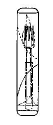
Figure 1 is a schematic side elevation view of
the apparatus of the present invention in one
embodiment.
Figure 2 is a schematic plan view of the
apparatus of Figure 1.
Figure 3 is a partial schematic perspective
view of the automatic wrapping mechanism of the
present invention.
Figures 4A - 4E are partial schematic top views
of a napkin and utensils, and the belt of Figure 3,
in various stages during the wrapping process.
Figures 5A - 5E are partial schematic side
elevation views of the napkin, utensils and belt
shown in corresponding Figures 4A-4E.
Figure 6 is a partial schematic perspective
view of an alternative embodiment of the automatic
wrapping mechanism of the present invention.
Figures 7A - 7E are partial schematic side
elevation views of a napkin and utensils, and the
belt of Figure 6, in various stages during the
wrapping process.
Figure 8 is a detail schematic cross-sectional
view of one utensil magazine of a silverware
delivery apparatus.
Figure 9 is a detail schematic view of a gummed
band dispenser.
Figure 10 is a partial schematic perspective
view of a second alternative embodiment of the
automatic wrapping mechanism of the present
CA 0222914~ 1998-02-10
W O 97/08052 PCT~US95/10735
invention.
Detailed Description of the Preferred Embodiments
Referring to Figure~ 1-2, a representative
embodiment of the wrapping apparatus 10 for wrapping
utensils 12 in a napkin 14 is shown con~igured for
completely automatic operation. In accordance with
the present invention, the apparatus 10 includes a
receiving area 18 and a mechanism 20 for
automatically wrapping at least one napkin 14 around
at least one utensil 12 provided in the receiving
area 18. Completely automatic operation is provided
by including a napkin dispenser 62 which
automatically loads at least one napkin 14 in the
receiving area 18, and an utensil dispenser 82 which
automatically delivers utensils 12 to the receiving
area 18. Means for securing the wrapped utensils 16
in a wrapped condition, such as a gummed band
dispenser 90, i8 Eurther provided to dispense a
gummed band 92 around the wrapped utensils 16.
Gummed band dispenser 90 is shown in greater detail
in Figure 9. The gummed band 92 serves as a napkin
ring to maintain the napkin 14 in wrapped
relationship, and preferably includes on one side an
adhesive such as those well known for use with
postable note papers.
Re~erring now to Figure 3, the mechanism 20 for
automatically wrapping includes a frame 22, and a
flexible belt 24 therein. The flexible belt has a
first surface 26 for frictional contact with at
least a portion of a napkin 14 provided in the
receiving area 18. At least a portion of the
flexible belt 24 is movable for manipulation of a
napkin 14 so provided. The mechanism 20 for
automatically wrapping includes a belt manipulation
CA 0222914~ 1998-02-10
- W O 97/08052 PCTrUS95/10735
device 30 to move the movable portion of the belt 24
~ to urge the napkin 14 in contact therewith to
= automatically wrap the utensils 12.
As shown in Figure 3, it is preferred that the
flexible belt 24 is connected at its opposite ends
24a, 24b, to the frame 22, with the movable portion
of the belt 24 positioned between the ends. The
frame 22 preferably includes a generally planar
- supporting surface 32 (shown best in Figure 1), such
as a flat surface or screen, which is in contact
with the preferably low friction second surface 28
of the flexible belt 24 and supports at least a
portion of the movable portion thereof. A part of
the movable portion of the belt 24 extends beyond
the planar supporting surface 32, and forms a first
trough 34, as shown in Figures 1 and 3.
The supporting surface 32 may further include
a means for restraining a portion of the napkin in
a flat position in the receiving area. One such
means for restraining is a vacuum table 39, shown in
phantom in Figure 3, which provides suction pressure
on napkin 14 through the interstices of the flexible
belt material. Such restraint is maintains the
position of napkin 14 against undesirable
displacement when loading utensils 12 upon a portion
of the napkin 14 extending into the trough 34.
The trough 34 is formed in the flexible belt 24
prior to wrapping either by gravity, or with
assistance of mechanical means such as fingers
(shown in Figure 6), or trough vacuum means 31, as
indicated in phantom in Figure 3. As further
indicated in phantom, the trough depth may be varied
by adjusting the level of trough plate 33 with a
gear drive 35. The trough depth is variable to
accommodate different types of napkins 14 which may
CA 0222914~ 1998-02-10
W O 97/08052 PCT~US95/10735
have varying flexibility and size, and is variable
to accommodate varying numbers of utensils 12.
Still referring to Figure 3, in the preferred
embodiment, the belt manipulation device 30
preferably comprises a slidable, rotatable first rod
36 extending across the flexible belt 24 in contact
with the second surface 28 thereof. The first rod
36 has a first position A, shown in Figures 3 and
5A, near end 24a of the flexible belt, where it is
positioned prior to automatically wrapping, and a
second position B nearer the opposite end 24b of the
flexible belt 24, as shown in Figure 5E, where its
travel terminates after producing wrapped utensils
16.
The belt manipulation device 30 further
includes a rod positioning device 40 connected to
the first rod 36, to automatically move the first
rod 36 between its first position A and second
position B. It is preferred that the rod
positioning device 40 include a pair of fixed cams
42 extending from the first position A to the second
position B along the sides of the belt 24, defining
a path of travel for the first rod 36 along the
frame 22. At least one, and preferably two cam
followers 46 attached to the first rod 36 through
bearings 44 allow free rotation of the ends of the
rod 36 and cam followers 46 as they move along cams
42.
Rod positioning device 40 also includes a drive
48, such as a belt drive rotatably driven by a
reversible drive motor 50. Alternatively, the drive
48 could include a hand crank. The drive 48
includes identical elements on both sides of the
flexible belt 24, except for the motor 50, and the
description which follows applies to portions of the
CA 0222914~ 1998-02-10
-
W097/080s2 PCT~S95/1073
drive 48 on each side of the belt 24.
Drive 48 further includes first and second
pulleys 53, 54 and a drive belt 56 which extends
therebetween. Second pulleys 54 are mounted on
drive axle 51, while first pulleys 52 are mounted to
respective sub-frames (which are not shown for
clarity) extending between the first and second
pulleys 52, 54. The sub-frames pivot around axis W.
Motor 50 connects to drive axle 51 to rotatably
drive the second pulleys 54, and the drive belt 56.
The drive belt 56 is positively connected to the
first rod 36 via a bearing 44b which allows the
first rod 36 to freely rotate as the drive belt 56
moves the first rod 36 along the cams 42. Such
positive connection of the rod to the drive belt 56
also causes permits the cam 42 and cam follower 46
to provide some support to the drive 48.
At the first pulley 52, the drive 48 is
supported by the frame bearing pad 23. First pulley
52 is also attached to the frame 22 by a spring 58
which allows vertical displacement of the cam
follower 46 as well as additional vertical
displacement of the first rod 36 to accommodate
vertical displacement in the position of first rod
36 during wrapping. The rod positioning device 40
of Figure 3 is preferred as it provides flexibility
in the vertical location of first rod 36 by
permitting both deflection of the drive belt 56 and
extension of the spring 58. As well, the belt drive
permits some belt slippage in the event of jamming.
A motor clutch (not shown) also may be provided to
disengage the drive motor 50 in the event of
jamming.
First and second limit switches 60a, 60b or
other motor control means may be used to control the
CA 0222914~ 1998-02-10
W O 97/080~2 PCT~US95/1073
travel of the first rod 36 between the first and
second positions A, B. Upon reaching a limit
switch, the drive motor 50 reverses to return the
first rod 36 to its opposite position.
During operation, illustrated in Figures 5A-5E,
the preferred belt manipulation device 30 permits
the first rod 36 to rotate due to frictional contact
with the second surface 28 of the flexible belt 24.
In this regard, such rotation prevents wear on the
low friction second surface 28 of flexible belt 24
otherwise imposed by a rigid rod. Alternatively,
the surface of the first rod 36 may be worked (e.g.
knurled) to increase friction, if desired, and
additional ribbing may be provided in the first rod
36 to assist in urging the napkin to wrap.
It ls understood that numerous other rod
positioning devices 40 are possible to provide the
desired motion of first rod 36 and flexible belt 24,
and that Figure 3 is illustrative of one, preferred
embodiment. For example, an alternative rod
positioning device 40 (not shown) may employ a pair
of coordinated screw drives, each rotatably driven
by a drive motor 50 located along axis W near second
end B, and which is also pivotable about axis W.
The screws of the screw drive extend from end B to
end A, on each side of the flexible belt 24, and a
drive nut is connected through a rotatable bearing
to the first rod 36. Rotation of the screws by
drive motor 50 causes the drive nut to move along
the length of the screw, moving the first rod 36
between the first position A and second position B
along cams 42. The screws may be supported in like
manner as the first pulley 52 at the end A, with a
bearing pad 23 for support and a spring 58 for
vertical displacement.
CA 0222914~ 1998-02-10
WO 97/08052 PCT~US95/10735
-
- 10
- Another alternative rod positioning device 40
(not shown) may employ a grooved first rod and a
mating, ribbed second surface 28 of belt 24.
Rotation of the grooved first rod imposed by a
traveling motor, permits the grooves to mesh with
the ribs on the second surface 28, advancing the
- grooved first rod from the first position A to
second position B along the cams 42. Reverse
rotation of the motor 50 returns the grooved first
rod to the first position A.
Other variants of the present invention may
include rod positioning devices 40 using levers,
rotating cams, gears drives, pistons and the like,
and such rod positioning devices are contemplated to
fall within the scope of the present invention.
Regardless of the precise drive 48 used, the transit
of the first rod 36 along the second surface 28 of
the flexible belt 24 across the frame 22 causes the
flexible belt to automatically roll a napkin 14
around at least one utensil 12, as shown in Figures
4A-4E and 5A-5E.
The mechanism 20 for automatically wrapping may
further include an element for tucking which urges
one end of the napkin 14 adjacent to one end of the
utensils 12 to tuck inward during wrapping to close
off one end of the bundle thus formed. This element
may comprise a fixed feature 21 (shown in phantom in
Figure 3) on the frame 22 which causes the napkin
positioned in the receiving area to form a tuck
(indicated in phantom in Figures 4C-4E), or may be
a moveable element, such as a large leaf spring 29,
as shown in phantom in Figure 3, which contacts an
edge portion of the flexible belt 24 to urge an end
to tuck.
Once the wrapped utensils 16 are produced, they
CA 0222914~ 1998-02-10
W O 97/08052 PCTAUS95/10735
are discharged from the flexible belt 24 by
continued motion of the first rod 36 towards the
second end B, as indicated in Figure 5E. Where a
gummed band is to be placed around the wrapped
utensils 16, it is preferred to apply it from a
dispenser 90, such as a roll and
cutter dispenser shown in Figures 1 and 9, which may
be fed from beneath the supporting surface 32
through a slot in the flexible belt 24.
Alternatively, a pre-cut gummed band may be
positioned on the surface of the flexible belt 24 by
a finger mechanism, or pre-applied to the outer
surface of the napkin 14 on its trailing edge 14t
prior to wrapping.
Referring now to Figure 6, an alternative
embodiment of the mechanism 20 for automatically
wrapping is shown where like elements have like
numbers. In the alternative embodiment, the
flexible belt comprises a continuous belt 124 which
is rotatable in at least one direction, and thus the
entire belt 124 is movable for manipulation of the
napkin 14 to automatically wrap the utensils 12. h
before, a portion of the belt 124 extends beyond the
planar supporting surface 32, and forms a first
trough 34, as shown in Figure 6 and 7B-7D.
In the alternative embodiment of Figure 6, the
belt manipulation device 130 includes a first rod 36
extending across the belt 124 in contact with the
second surface 28, and a generally planar supporting
surface 32 spaced from the first rod 36 and
supporting a portion of the belt 124. Preferably,
the belt manipulation device 130 includes a pair of
fingers 132 which extend to contact the first
surface 26 of the belt 124 along both belt edges,
and are initially positioned between the first rod
CA 0222914~ 1998-02-10
W O 97/08052 PCTAUS95/10735
-
12
36 and the supporting surface 32. The fingers 132
- depress a portion of the belt 124 to form the first
trough 34.
The belt manipulation device 130 also includes
a rod positioning device 140. The rod positioning
device 140 moves the first rod 36 from a first
position C shown in Figure 6 and 7A spaced laterally
from the supporting surface 32, to a second position
D shown in Figure 6 and 7D, spaced closer to, and
- 10 preferably above, the supporting surface 32 during
wrapping. The rod positioning device 140,
preferably further positions the fingers 132 to form
a first trough 34 in the belt 124 between the first
rod 36 and the supporting surface 32. The rod
positioning device 140 may, as before, take many
forms. In accordance with the alternative
embodiment of the present invention, as the motions
of the first rod 36 and fingers 132 are more
limited, it is preferred to provide a lever
mechanism positioned on each side of the belt 124
and shown in Figure 6 including lever 142, links
144a and 144b, and spring 146. The lever may be
driven by a motor (not shown), piston 150, solenoid
(not shown), manually or other operating means, to
cause automatic wrapping.
The belt manipulation device 130 further
includes a dancer roller 134 to both maintain
tension on the belt 124 and permit manipulation of
the belt 124 when the fingers 132 depress the belt
to form the trough 34 and the first rod 36 moves
between the first position C and the second position
D. In accordance with the alternative embodiment,
in operation, the continuous belt 124 is preferably
rotated as shown in Figures 7C and 7D when the first
rod 36 is moved to its second position D to urge the
CA 0222914~ 1998-02-lO
W O 97/08052 PCTrUS95/10735
napkin 14 to wrap around the utensil 12. Drive means
148 for rotating the belt 124, such as a belt drive
motor 49 are provided to rotate rollers 136
supporting the belt 124.
Thus, the motion of the first rod 36 from its
first to its second position C and D, in cooperation
with the supporting sur~ace 32 and rotation of the
belt 124 causes the napkin 14 to automatically roll
around the utensil 12.
Once the wrapped utensils 16 are produced, they
are discharged from the belt 124 (Figure 7E) by
returning the first rod 36 towards its first
position C, and continuing the same rotation of the
belt 124 as was provided during wrapping. In the
alternative embodiment, it is preferred to pre-apply
a gummed band 92 to a napkin 14 on its trailing edge
14t prior to wrapping. This may be accomplished by
mechanically positioning the gummed band in the
receiving area, or by applying it from a gummed band
dispenser 90, such as a roll and cutter dispenser in
like ~ashion as shown in Figure 9, through a gap in
the flexible belt 124. With this arrangement belt
124 becomes a pair of parallel belts which include
a gap therebetween.
As shown in Figure 6, for improved production
rates, a second, separately rotating, continuous
feed belt 126 may be included which provides both a
receiving area 118 for receiving a napkin 14 and
utensils 12. Thus, the apparatus 10 can wrap a
napkin and utensils on belt 124, while
simultaneously preparing the next napkin and
utensils on feed belt 126. When the belt 124
discharges the wrapped utensils 16, the next napkin
14 and utensils 12 can be simultaneously advanced
thereon, as shown in Figure 7E. A feed belt 126
CA 02229l4~ l998-02-lO
W 097/08052 PCTrUS95/10735
; 14
- further permits improved application of gummed bands
by making possible the application of gummed bands
92 at the feed belt 126 and receiving area 118 (not
shown) in like manner as previously described. As
well, the gummed bands 92 may be applied from either
below or between a transition element 125 as shown
in Figure 6, or otherwise through a gap between the
belts 126 and 124 (not shown). Where a feed belt
126 is used it may be desirable to apply an upward
- 10 burst of air with air jets 128, connected to a
source of positive pressure air, between transition
element 125 and belts 126 and 124 to prevent the
napkin 14 from diverting therebetween.
The alternative configuration of Figure 6 has
the advantage of requiring only a limited
displacement of first rod 36, and requires rotation
of belt 124 in only one direction. Further, where
a feed belt is used, a second set of utensils 12 may
be prepared on a napkin 14 for wrapping, while a
first set is being wrapped, increasing the capacity
and speed of the apparatus 10. Delivery of the
napkin 14 and utensils 12 for wrapping is further
improved by the single direction of belt rotation
which allows feeding from one end and discharge from
the other.
It is understood that a hybrid configuration of
the preferred and alternative embodiments of Figures
3 and 6 may be used where the continuous belt 124 of
Figure 6 is moved to bring the napkin 14 and
utensils 12 into position at the trough 34 in an
apparatus where the first rod 36 is configured as in
Figure 3 for movement between first and second
positions A and B. To achieve this end, trough
plate 33 may be raised to approximately the level of
the supporting surface 32 to receive the napkin 14
CA 0222914~ 1998-02-10
W O 97/08052 PCT~US95/10735
and utensils 12 to maintain their desired
relationship, and then lowered to begin folding and
wrapping. The continuous belt 124 can be locked in
position during movement of the first rod 36, with
necessary slack provided by a dancer roll, to
perform in essentially the same manner as in the
preferred embodiment of Figure 3.
Referring now to Figures 1 and 2, completely
automatic operation of the apparatus 10 can be
provided by including a napkin dispenser 62 which
automatically loads at least one napkin 14 in the
receiving area 18 (or 118), and an utensil dispenser
82 which automatically delivers utensils 12 to the
receiving area 18 (or 118). The illustrative napkin
dispenser 62 of Figures 1 and 2 includes a frame 64
which supports a tray 66, and a tray elevator 68,
such as an elevator motor 72 and a conventional
belt, chain or gear drive (not shown). Means 70 for
controlling the elevator include a stack height
sensor 74 to maintain the stack height at the
desired level with the motor 72. A tray elevation
sensor 76 may also be used to detect when the tray
66 is empty. A vacuum plate 78 is mounted on an arm
80 which pivots as shown in Figure 2 from the stack
to the receiving area 18 (or 118). The arm 80
lowers to pick up a napkin 14 at the stack by
vacuum, raises (as shown in phantom) to lift the
napkin, and lowers to position the napkin for
release at the receiving area 18 (or 118). Such
raising and lowering can be induced by action of a
cam (not shown) which is engaged when the arm 80
pivots, or by other means. Other napkin dispensing
devices are possible, and the dispenser 62 shown is
illustrative. Napkins 14 are preferably cloth or
paper, and each material will require a slightly
CA 0222914~ 1998-02-10
W097/08052 PCT~S95/10735
16
dif~erent dispensing means. It is noted that the
- position of the napkin dispensed at the receiving
area in Figures 3 and 6 is pre~erably diagonal, so
that the leading edge 141 of the napkin actually
comes to a point o~ the napkin, and the trailing
edge 14t comes to another point. It is also
pre~erable to position folded napkins such that the
sides which form the leading edge 141 are folded
edges.
Further illustratively shown in Figures 1 and
2, a utensil dispenser 82 is shown having a
plurality of magazines 84, one type of utensil 12
being placed in each magazine 84. A motor 86
mounted on dispenser ~rame 87 is provided to
incrementally position the magazines 84 as desired,
for dispensing desired utensils 12 therefrom. Motor
86 is preferably a belt drive motor. Utensils 12
can be loaded in the magazines 84 manually or
automatically after sorting. As ~urther shown in
Figure 8, solenoid or air operated pins 88u, 881 may
be used to separate and dispense utensils 12 from
the magazines 84. The pins 88u, 881 are preferably
pointed to improve insertion between utensils 12,
and extend at least hal~way across the width o~ the
magazine 84. One pair of pins 881 is positioned
below, and one pair o~ pins 88u is positioned above,
the bottom utensil 12 in a stack. To dispense a
utensil 12, both pairs of pins 881 and 88u begin in
extended position, and the lower pair of pins 881
are retracted, while the upper pins 88u support the
stack. Then, the lower pins 881 are again extended,
and the upper pins 88u retracted to allow the stack
o~ utensils 12 to drop. Then, the upper pins 88u
are again extended.
Alternatively, a series of ~ixed, parallel
CA 0222914~ 1998-02-10
W O 97/080~2 PCTrUS95/1073
magazines 84 feeding into a common chute (not shown)
can be used to dispense the utensils 12 to the
receiving area.
Finally, it is possible to combine an automatic
silverware sorting apparatus with the apparatus of
the present invention. One such apparatus is shown
in U.S. Patent No. 3,394,804, issued July 30, 1968
to Reichel, to further automate the entire process.
Other features discussed with regard to the
preferred embodiment, such as the adjustable trough
plate 33 and vacuum table 39, can be also provided
in the various alternative embodiments of the
present invention to enhance the performance and
capabilities of the apparatus 10. As well, other
features of the alternative embodiments, such as the
feed belt 126, transition element 125, air jets 128,
and continuous belt 124 may be added to the
pre~erred embodiment to achieve the advantages
thereof.
Referring now to Figure 10, a second
alternative embodiment is shown in which like
numbers represent like elements. The drum-like
arrangement of Figure 10 is illustrative of the
various alternative embodiments which may produce
the folding and rolling of the napkin 14 and
utensils 12 illustrated in accordance with the
present invention in Figures 7A-7E. The rotating
drum 100 preferably includes ~ive sections, each of
which includes a continuous belt 124 mounted on a
plurality of rollers. Two larger rollers 102 and
104 are operable from a first, separated position to
a second, closed position. The relationship between
the rollers 102, 104 (and effect on the napkin 14
and utensil 12) is similar to that between the first
rod 36 and supporting sur~ace 32 in the alternative
CA 0222914~ 1998-02-10
= W097/08052 PCT~S95/10735
embodiment of Figure 6. In that alternative, the
first rod 36 is separated from, and then brought
into opposing relationship with, the supporting
surface 32, as shown in Figures 7A and 7D. In the
~ 5 second alternative embodiment of Figure 10, rollers
102 and 104 are supported at their ends by shafts
103 and 105 (only partially shown for clarity) which
are preferably hinged at the hub 109. The position
of rollers 102 and 104 is controlled by mechanical
connection to cam follower 108 which travels in
fixed cam 106 (the path of which is shown in
phantom).
The drum 100 rotates by conventional connection
to a motor (not shown). Each section of the drum is
- 15 divided by a spoke 110, and each spoke 110 includes
a vacuum means 112 at its ends which serves to
receive a gummed band 92 from gummed band dispenser
90 and a napkin 14 from the napkin dispenser 62.
Preferably, each spoke 110 extends across the width
of the drum 100. The path of a spoke 110 as it
travels on the drum will further illustrate the
structure and function of this alternative
embodiment. At approximately the seven o'clock
position, the vacuum means 112 of spoke 110 contacts
a fixed vacuum source 114, and the vacuum means 112
receives and restrains a gummed band 92 severed by
cutter 94 from a roll of gummed bands. The sticky
side of the band 92 faces away from the drum 100.
As the spoke 110 carries the gummed band 92 to
approximately the nine o'clock position, the vacuum
means 112 further contacts and receives a napkin 14
delivered by the vacuum plate 78 from the stack.
Part of the edge of the napkin 14 also adheres to
part of the gummed band 92. As the spoke 110
continues towards the 12 o'clock position, utensils
CA 0222914~ 1998-02-10
W O 97/08052 PCT~US95/10735
12 are deposited upon the belt 124, preferably by
means of an utensil dispenser 82 which includes a
gate 89 which lowers by mechanical or electrical
means in time with the drum rotation. Up to this
point, the belt 124 has been static. As the spoke
110 continues past approximately the 12 o'clock
position, the rollers 102, 104 close into generally
opposing relationship under action of the cam 106
and cam follower 108. The belt 124 is then rotated
by convéntional means, such as a belt drive 116
(shown in phantom) which contacts at least one end
of the surface of rollers 102, 104 or belt 124, or
both, or a pin drive (not shown), or the like, in
time with the drum rotation, causing the napkin 14
and utensils 12 to roll, as illustrated in Figure
7D. This action further causes the gummed label 92
to secure the napkin 14 and utensils 12 in rolled
relationship. The belt rotation is stopped, and,
finally, as the spoke 110 moves to approximately the
5 o'clock position, the wrapped utensils 16 are
discharged by gravity.
The alternative embodiment of Figure 10 has the
advantage of simultaneous operation upon multiple
napkins 14 and utensils 12, improving production
rates. As well, the napkin 14 can be dispensed with
either a flat or pointed leading edge. However, the
complexity of the alternative embodiment of Figure
10 results in higher manufacturing costs.
In accordance with the present invention, the
materials of construction are preferably stainless
steel or corrosion resistant steel for most metallic
materials. The material of flexible belt 24 (and
124) may be any flexible material which, preferably,
has a coefficient of friction on the first surface
26 sufficient to induce a napkin 14 to fold and
~ CA 0222914~ 1998-02-10
-
W097/080s2 ~CT~S95/10735
- 20
roll, and a low friction coating or quality on the
second surface 28. By way of example and not
limitation, a teflon coated canvas material could
serve as flexible belt 24.
In a further aspect of the present invention,
a method for automatically wrapping at least one
utensil 12 in a napkin 14 is provided including the
- steps of positioning at least one utensil 12 and at
least one napkin 14 in a receiving area 18, as shown
in Figures 4A, 5A, 7A and 7E, and then manipulating
the napkin 14 with an automatic wrapping mechanism
20, manually or automatically powered, to
automatically wrap the napkin 14 around the utensils
12, as further illustrated in Figures 4B-4E, 5B-5E,
and 7B-7D.
One surface of the napkin 14 may be said to
include first and second side portions 14a, 14c and
a central portion 14b therebetween, as indicated in
Figure 4A, so that, more specifically, the step of
positioning includes positioning the utensil 12 in
one of the portions 14a, 14b, 14c of the napkin 14.
The step of manipulating includes automatically
folding at least part of one of the portions over
the utensils 12 into generally opposing relationship
with at least part of another of the portions, as
illustrated in Figures 4C and D, 5C and D and 7C and
D, and urging the napkin 14 to roll around and wrap
the utensils 12 into a bundle, or wrapped utensils
16. During the step of urging, the utensils 12 tend
to move towards the central portion 14b of the
napkin 14, and the opposing portions of the napkin
tend to wrap in unison generally around the utensils
12.
Depending upon how the step of positioning
establishes the initial position of the utensil 12
CA 0222914~ 1998-02-10
W O 97/08052 PCT~US95/10735
on the napkin, the step of manipulating can result
in wrapping the napkin 14 around the utensil 12
approximately from edge to edge, or can result in
substantially ~olding the napkin 14 in half over the
utensils 12 and rolling the opposing halves together
around the utensils 12.
In accordance with Figures 1, 4A and 7A, it is
understood that where a napkin dispenser 62 is
provided, the step of positioning includes
automatically positioning the napkin 14 in the
receiving area 18 (or 118). Where an utensil
dispenser 82 is provided, it is further understood
that the step of positioning includes automatically
positioning at least one utensil 12 in the receiving
area 18 (or 118).
As is understood from the description of the
apparatus 10, the step of manipulating is performed
by frictionally engaging at least a portion of the
napkin 14 with a movable portion of the flexible
belt 24 (or 124), and moving that portion to urge
the napkin 14 into wrapped relationship around the
utensils 12. Where a means for restraining the
napkin, such as a vacuum table 39 is included in the
apparatus 10, the step of manipulating includes the
step of initially restraining a portion of said at
least one napkin 14 in a flat position in the
receiving area 18 (or 118). And, where the wrapping
apparatus 10 includes an element for tucking an end
of the napkin 14 during wrapping(e.g. a fixed
feature 21 or leaf spring 29), as shown in Figure 3,
the step of manipulating includes tucking inward an
edge of the central portion 14b of the napkin 14.
Such a tuck is desirable to produce one closed end
in the bundle of wrapped utensils 16. To permit
fixed feature 21 to ~unction, the napkin 14 must be
~ CA 0222914~ 1998-02-10
-
W O 97/08052 PCTAUS95/10735
selectively placed in the receiving area 18 to
engage the fixed feature 21, as shown in Figure 2.
The method includes further steps where
additional elements are included in apparatus 10.
Thus, where a gummed band dispenser 90 is included
; in the apparatus lO, the method of the present
- invention further includes the step of securing the
napkin 14 in wrapped condition around at least one
utensil 12. Where an automatic silverware sorting
apparatus is included, the method of the present
invention further includes, prior to the step of
positioning, the step of automatically sorting at
least one utensil 12 in an automatic silverware
sorting apparatus. Finally, where an utensil
dispenser 82 is included in the apparatus 10, the
method includes the step of automatically delivering
at least one utensil to the receiving area 18 (or
118) from the utensil dispenser 82.
Where the apparatus 10 of the alternative
embodiments of Figures 6 and 10 are used, the method
of the present invention is performed with the same
steps as set forth above. In this regard, as may be
understood from Figures 4A-4E, 5A-5E, and 7A-7E, the
wrapping process imposed by the belts 24 and 124
upon the napkin 14 follows the same essential steps.
Where using the alternative embodiment of Figures 6
and 10, the steps of feeding the napkin and utensil
from a receiving area 118 may be included, as
illustrated in Figures 7A and 7E. In addition, the
step of rotating the belt 124 is included in the
step of manipulating, as illustrated in Figures 7C
and 7D.
While certain representative embodiments and
details have been shown for purposes of illustrating
the present invention, it will be apparent to those
CA 0222914~ 1998-02-10
W O 97/08052 PCTAUS95/10735
skilled in the art that various changes in the
apparatus and method disclosed herein may be made
without departing from the scope of the invention,
which is defined in the appended claims.