Language selection

Search

Patent 2229189 Summary

Third-party information liability

Some of the information on this Web page has been provided by external sources. The Government of Canada is not responsible for the accuracy, reliability or currency of the information supplied by external sources. Users wishing to rely upon this information should consult directly with the source of the information. Content provided by external sources is not subject to official languages, privacy and accessibility requirements.

Claims and Abstract availability

Any discrepancies in the text and image of the Claims and Abstract are due to differing posting times. Text of the Claims and Abstract are posted:

  • At the time the application is open to public inspection;
  • At the time of issue of the patent (grant).
(12) Patent Application: (11) CA 2229189
(54) English Title: TOUCH SENSOR CIRCUIT
(54) French Title: CIRCUIT DE COMMANDE A EFFLEUREMENT
Status: Deemed Abandoned and Beyond the Period of Reinstatement - Pending Response to Notice of Disregarded Communication
Bibliographic Data
(51) International Patent Classification (IPC):
  • H03K 17/96 (2006.01)
  • H05B 39/08 (2006.01)
(72) Inventors :
  • JAROS, JEFFREY J. (United States of America)
(73) Owners :
  • THE LAMSON & SESSIONS CO.
(71) Applicants :
  • THE LAMSON & SESSIONS CO. (United States of America)
(74) Agent: MARKS & CLERK
(74) Associate agent:
(45) Issued:
(22) Filed Date: 1998-02-10
(41) Open to Public Inspection: 1998-08-11
Examination requested: 1998-02-10
Availability of licence: N/A
Dedicated to the Public: N/A
(25) Language of filing: English

Patent Cooperation Treaty (PCT): No

(30) Application Priority Data:
Application No. Country/Territory Date
08/799,118 (United States of America) 1997-02-11

Abstracts

English Abstract


A touch sensitive sensor circuit having a touch input, pad for receiving a
person's touch, and a power switching circuit for applying AC power to a load,
wherein the Ac power includes a line-hot and line-neutral input, and wherein a
person's touch on the touch input pad creates a circuit connection between the
line-hot AC input and earth ground that triggers the power switch, the touch
sensor circuit comprising a sense input circuit connected between the touch
input pad and the power switching circuit and a power supply and reference
circuit including AC to DC conversion circuitry that generates positive ground
DC voltage references that track the line-hot AC input, and that supply DC
power to the sense input circuit and the power switching circuitry .


Claims

Note: Claims are shown in the official language in which they were submitted.


-20-
What is claimed:
1. A touch sensor circuit having a touch input pad
for receiving a person's touch, and a power
switching circuit for applying AC power to a load,
wherein the AC power includes a line-hot and
line-neutral input, and wherein a person's touch on the
touch input pad creates a circuit connection between
the line-hot AC input and earth ground that triggers
the power switch, the touch sensor circuit
comprising:
a sense input circuit connected between the
touch input pad and the power switching circuit; and
a power supply and reference circuit including
AC to DC conversion circuitry that generates
positive and ground DC voltage references that track
the line-hot AC input, and that supply DC power to
the sense input circuit and the power switching
circuitry.
2. The touch sensor circuit according to claim 1,
wherein the sense input circuit includes a pull-up
resistor connected between a sense node and the
positive DC reference voltage.

-21-
3. The touch sensor circuit according to claim 2,
wherein a sense signal is generated by the sense
input circuit at the sense node when a person
touches the touch pad, a.nd wherein the sense signal
is generated by the voltage drop across the pull-up
resistor from the circuit connection between the
line-hot AC input and earth ground through the
person's body.
4. The touch sensor circuit according to claim 2,
wherein the sense input circuit further includes a
current limiting resistor connected between the
touch input pad and the sense node.
5. The touch sensor circuit according to claim 2,
wherein the power switching circuit includes a
one-shot trigger circuit, flip flop and relay.
6. The touch sensor circuit according to claim 5,
wherein the one-shot trigger circuit is connected to
the sense node of the sense input circuit, and
wherein the one-shot trigger circuit detects a
voltage drop on the sense node corresponding to a

-22-
person touching the touch pad and generates a
trigger pulse on its output.
7. The touch sensor circuit according to claim 6,
wherein the period of the trigger pulse generated by
the one-shot trigger circuit is adjustable.
8. The touch sensor circuit according to claim 6,
wherein the flip flop input is connected to the
output of the one-shot trigger circuit and the flip
flop output is connected to the relay.
9. The touch sensor circuit according to claim 8,
wherein the pulse generated by the one-shot trigger
circuit toggles the output of the flip flop, thereby
causing the relay to open and close.
10. The touch sensor circuit according to claim 9,
wherein the relay is connected between AC power and
the load, such that when the one-shot toggles the
output of the flip flop, the relay successively
applies and removes power from the load.

-23-
11. The touch sensor circuit according to claim 1,
wherein the power supply and reference circuit
includes a diode bridge :rectifier connected to AC
power and a DC reference circuit connected to the
diode bridge, the DC reference circuit providing the
positive and ground DC reference voltages that track
the line-hot AC power input.
12. The touch sensor circuit according to claim 11,
wherein the power supply and reference circuit
further includes an RC network connected between the
line-neutral AC input and the diode bridge
rectifier.
13. A touch sensor circuit for switching AC power to
a load, said AC power including line-hot and
line-neutral inputs, the circuit comprising:
a touch input pad;
a sense input circuit connected to the touch
input pad, the sense input circuit including a sense
signal that is generated when a person touches the
touch input pad;

-24-
a logic circuit connected to the sense input
circuit for generating a trigger pulse in response
to the sense signal;
and
a power switch connected to the logic circuit;
a power supply that converts AC power to DC
voltage references that track the line-hot AC input,
wherein the voltage references supply DC power to
the sense input circuit, logic circuit and power
switch.
14. The touch sensor circuit according to claim 13,
wherein the DC reference voltages include positive
and ground references.
15. The touch sensor circuit according to claim 14,
wherein the sense input circuit includes a pull-up
resistor connected between the positive DC reference
voltage and a sense node, and wherein the touch
input pad is connected to the sense node.
16. The touch sensor circuit according to claim 15,
wherein the sense input circuit includes a current

Description

Note: Descriptions are shown in the official language in which they were submitted.

Sorry, the description for patent document number 2229189 was not found. Text is not available for all patent documents. The current dates of coverage are on the Currency of Information  page
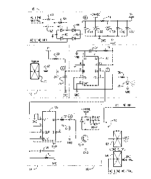
Representative Drawing
A single figure which represents the drawing illustrating the invention.
Administrative Status

2024-08-01:As part of the Next Generation Patents (NGP) transition, the Canadian Patents Database (CPD) now contains a more detailed Event History, which replicates the Event Log of our new back-office solution.

Please note that "Inactive:" events refers to events no longer in use in our new back-office solution.

For a clearer understanding of the status of the application/patent presented on this page, the site Disclaimer , as well as the definitions for Patent , Event History , Maintenance Fee  and Payment History  should be consulted.

Event History

Description Date
Inactive: IPC expired 2020-01-01
Inactive: IPC from MCD 2006-03-12
Time Limit for Reversal Expired 2001-02-12
Application Not Reinstated by Deadline 2001-02-12
Inactive: Prior art correction 2000-06-20
Deemed Abandoned - Failure to Respond to Maintenance Fee Notice 2000-02-10
Application Published (Open to Public Inspection) 1998-08-11
Amendment Received - Voluntary Amendment 1998-06-04
Classification Modified 1998-05-21
Inactive: IPC assigned 1998-05-21
Inactive: First IPC assigned 1998-05-21
Inactive: IPC assigned 1998-05-21
Inactive: Correspondence - Formalities 1998-05-11
Filing Requirements Determined Compliant 1998-05-01
Inactive: Filing certificate - RFE (English) 1998-05-01
Application Received - Regular National 1998-05-01
All Requirements for Examination Determined Compliant 1998-02-10
Request for Examination Requirements Determined Compliant 1998-02-10

Abandonment History

Abandonment Date Reason Reinstatement Date
2000-02-10

Fee History

Fee Type Anniversary Year Due Date Paid Date
Request for examination - standard 1998-02-10
Application fee - standard 1998-02-10
Registration of a document 1998-02-10
Owners on Record

Note: Records showing the ownership history in alphabetical order.

Current Owners on Record
THE LAMSON & SESSIONS CO.
Past Owners on Record
JEFFREY J. JAROS
Past Owners that do not appear in the "Owners on Record" listing will appear in other documentation within the application.
Documents

To view selected files, please enter reCAPTCHA code :


To view images, click a link in the Document Description column. To download the documents, select one or more checkboxes in the first column and then click the "Download Selected in PDF format (Zip Archive)" or the "Download Selected as Single PDF" button.

List of published and non-published patent-specific documents on the CPD .

If you have any difficulty accessing content, you can call the Client Service Centre at 1-866-997-1936 or send them an e-mail at CIPO Client Service Centre.


Document
Description 
Date
(yyyy-mm-dd) 
Number of pages   Size of Image (KB) 
Abstract 1998-02-10 1 20
Description 1998-02-10 19 510
Drawings 1998-02-10 1 24
Drawings 1998-05-11 1 27
Cover Page 1998-08-24 1 53
Claims 1998-02-10 6 137
Representative drawing 1998-08-24 1 12
Courtesy - Certificate of registration (related document(s)) 1998-05-01 1 116
Filing Certificate (English) 1998-05-01 1 163
Reminder of maintenance fee due 1999-10-13 1 111
Courtesy - Abandonment Letter (Maintenance Fee) 2000-03-09 1 183
Correspondence 1998-05-01 1 23
Correspondence 1998-05-11 2 54