Language selection

Search

Patent 2229247 Summary

Third-party information liability

Some of the information on this Web page has been provided by external sources. The Government of Canada is not responsible for the accuracy, reliability or currency of the information supplied by external sources. Users wishing to rely upon this information should consult directly with the source of the information. Content provided by external sources is not subject to official languages, privacy and accessibility requirements.

Claims and Abstract availability

Any discrepancies in the text and image of the Claims and Abstract are due to differing posting times. Text of the Claims and Abstract are posted:

  • At the time the application is open to public inspection;
  • At the time of issue of the patent (grant).
(12) Patent Application: (11) CA 2229247
(54) English Title: METHOD OF CONVERTING A MOTOR VEHICLE INTO A TRACKED VEHICLE
(54) French Title: METHODE DE CONVERSION D'UN VEHICULE AUTOMOBILE EN UN VEHICULE A CHENILLES
Status: Deemed Abandoned and Beyond the Period of Reinstatement - Pending Response to Notice of Disregarded Communication
Bibliographic Data
Abstracts

English Abstract


A method of converting a motor vehicle into a tracked
vehicle. The first step involves non-rotatably securing a
dual rear wheel to each rear wheel. The second step involves
mounting an idler wheel forward of each rear wheel. Each idler
wheel is on a common plane with one of the dual rear wheels.
The third step involves encircling each dual rear and each
idler wheel with a continuous track.


Claims

Note: Claims are shown in the official language in which they were submitted.

4
THE EMBODIMENTS OF THE INVENTION IN WHICH AN EXCLUSIVE PROPERTY
OR PRIVILEGE IS CLAIMED ARE DEFINED AS FOLLOWS:
1. A method of converting a motor vehicle into a tracked
vehicle, comprising the steps of:
non-rotatably securing a dual rear wheel to each rear
wheel;
mounting an idler wheel forward of each rear wheel, each
idler wheel being on a common plane with one of the dual rear
wheels; and
encircling each dual rear and each idler wheel with a
continuous track.

5
2. A method of converting a motor vehicle into a tracked
vehicle, comprising the steps of:
non-rotatably securing a dual rear wheel to each rear
wheel bar bolting a collar between the rear wheel and the dual
rear wheel, such that rotation of the rear wheel results in
rotation of the dual rear wheel;
mounting an idler wheel forward of each rear wheel by
attaching a idler wheel support to a frame of the motor
vehicle, each idler wheel being on a common plane with one of
the dual rear wheels; and
encircling each dual rear wheel and each idler wheel with
a continuous track, such that rotation of the dual rear wheel
moves the continuous track with movement of the track being
supported by the idler wheel.

Description

Note: Descriptions are shown in the official language in which they were submitted.


CA 02229247 1998-02-11
1
TITLE OF! THE INVENTION:
method of converting a motor vehicle into a tracked
vehicle
NAMES) OF INVENTOR(S):
Norman Campbell
FIELD Ol? THE INVENTION
The' present invention relates to a method of converting
a motor vehicle into a tracked vehicle and, in particular, an
all terrain vehicle commonly known as a "quad".
BACKGROZTND OF THE INVENTION
Four wheeled all terrain motor vehicles known as "quads"
have become very popular in North America. However, quads have
difficu=Lty manoeuvring in deep snow. There have been attempts
to modij=y quads to convert them to tracked vehicles, but such
attempt: have, to date, not been successful. Once unsuccessful
attempt marketed by Great West Golf & Industrial Inc . which
operate; out of Edmonton, Alberta involved the use of rear
mounted idler wheels. A track was supported between the rear
wheels of the quad and the rear mounted idler wheels. This
quad tended to ride high in the back and, therefore, tended to
nosedive. into snow drifts. Another unsuccessful attempted
marketed by Kimpex Inc. which operates out of Drummondville,
Quebec :involved the use of a centrally mounted undercarriage
track. This quad rode over the snow, but lacked lateral
stability. It was taken off the market after several
accidents involving quads that tipped over while manoeuvring.
SUN~IARY OF THE INVENTION
Whet is required is an alternative method of converting
a quad into a tracked vehicle.
According to the present invention there is provided a
method of converting a motor vehicle into a tracked vehicle.
The first step involves non-rotatably securing a dual rear

CA 02229247 1998-02-11
2
wheel to each rear wheel. The second step involves mounting
an idler wheel forward of each rear wheel. Each idler wheel
is on a common plane with one of the dual rear wheels. The
third step involves encircling each dual rear and each idler
wheel wuth a continuous track.
The' method, as described above, has been found to provide
the requisite buoyancy for the quad to enable it to manoeuvre
in dee~~ snow while also providing the requisite lateral
stability.
BRIEF DESCRIPTION OF THE DRAWINGS
These and other features of the invention will become more
apparent: from the following description in which reference is
made to the appended drawings, wherein:
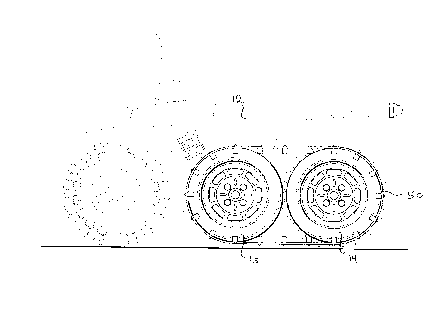
FIGURE 1 is a side elevation view of a quad that has been
converted into a tracked vehicle in accordance with the
teachings of the present invention.
FIGURE 2 is a bottom plan view of the quad illustrated in
2 0 FIGURE :L .
FI(=URE 3 is a first rear elevation view, in section, of
the quad illustrated in FIGURE 1.
FI(=URE 4 is a second rear elevation view, in section, of
the quad illustrated in FIGURE 1.
DETAIhEI) DESCRIPTION OF THE PREFERRED EMBODIMENT
The' preferred method of converting a motor vehicle into
a tracked vehicle will now be described with reference to
FIGURES 1 through 4.
Rei=erring to FIGURES 1 and 2, there is illustrated a quad
12 as it: appears after conversion into a track vehicle with a
dual rear wheel 14 and an idler wheel 15. Referring to FIGURE
3, the first step in effecting this conversion is to non-
rotatab=Ly secure a dual rear wheel 14 to each rear wheel 16 by
bolting a collar 18 between rear wheel 16 and dual rear wheel
14. Collar 18 has a first flange 20 with a plurality of

CA 02229247 1998-02-11
3
mounting apertures 23 and a second flange 22 with a plurality
of mounting bolts 24. Mounting bolts 26 on axle 28 extend
through mounting apertures 23 on first flange 20. Nuts 30 are
then used to secure collar 18 in position. Dual rear wheel 14
is then. mounted onto mounting bolts 24 that extend from
secondary flange 22 and secured in position by nuts 32. It
will be apparent that with this mode of mounting, rotation of
rear wheel 16 results in rotation of dual rear wheel 14.
Referring to FIGURES 2 and 4, idler wheels 15 are mounted
forward of each rear wheel 16 by attaching a idler wheel
support bracket 34 to a frame 36 of quad 12. The mode of
attachment illustrated is by means of nuts 38 and bolts 40.
This mode of attachment is preferred as it enables idler wheel
support bracket 34 to be readily removed when not required.
Referring to FIGURE 2, it is to be noted that each idler wheel
15 is on a common plane with one of dual rear wheels 14, as
indicatEad by reference numeral 42. Referring to FIGURE 4,
idler wheel support bracket 34 includes rotatable portion 44,
to which idler wheel 15 is mounted by means of mounting bolts
46 and :tuts 48. Referring to FIGURES 1 and 2, a continuous
track 50 encircles each dual rear wheel 14 and each idler wheel
15. Rogation of dual rear wheel 14 moves continuous track 50
with mo~rement of track 50 being supported by idler wheel 15.
The' forward positioning of idler wheel 15 provides
buoyanc~r for quad 12 when travelling over snow. The lateral
positioning of both idler wheels 15 and dual rear wheels 14
provider quad 12 with a wide and stable stance.
Although this present invention was developed for use with
an all terrain vehicle, and has been illustrated with reference
to an a7.1 terrain vehicle; it will be apparent to one skilled
in the art that the teachings are transferable to other types
of motor vehicles. It will also be apparent to one skilled
in the art that modifications may be made to the illustrated
embodiment without departing from the spirit and scope of the
invention as hereinafter defined in the Claims.

Representative Drawing
A single figure which represents the drawing illustrating the invention.
Administrative Status

2024-08-01:As part of the Next Generation Patents (NGP) transition, the Canadian Patents Database (CPD) now contains a more detailed Event History, which replicates the Event Log of our new back-office solution.

Please note that "Inactive:" events refers to events no longer in use in our new back-office solution.

For a clearer understanding of the status of the application/patent presented on this page, the site Disclaimer , as well as the definitions for Patent , Event History , Maintenance Fee  and Payment History  should be consulted.

Event History

Description Date
Application Not Reinstated by Deadline 2002-02-11
Time Limit for Reversal Expired 2002-02-11
Deemed Abandoned - Failure to Respond to Maintenance Fee Notice 2001-02-12
Amendment Received - Voluntary Amendment 2000-01-05
Letter Sent 1999-12-10
Request for Examination Received 1999-11-23
All Requirements for Examination Determined Compliant 1999-11-23
Request for Examination Requirements Determined Compliant 1999-11-23
Inactive: Cover page published 1999-08-18
Application Published (Open to Public Inspection) 1999-08-11
Inactive: First IPC assigned 1998-06-03
Classification Modified 1998-06-03
Inactive: IPC assigned 1998-06-03
Filing Requirements Determined Compliant 1998-05-04
Inactive: Filing certificate - No RFE (English) 1998-05-04
Application Received - Regular National 1998-05-02

Abandonment History

Abandonment Date Reason Reinstatement Date
2001-02-12

Maintenance Fee

The last payment was received on 1999-11-23

Note : If the full payment has not been received on or before the date indicated, a further fee may be required which may be one of the following

  • the reinstatement fee;
  • the late payment fee; or
  • additional fee to reverse deemed expiry.

Please refer to the CIPO Patent Fees web page to see all current fee amounts.

Fee History

Fee Type Anniversary Year Due Date Paid Date
Application fee - small 1998-02-11
Request for examination - small 1999-11-23
MF (application, 2nd anniv.) - small 02 2000-02-11 1999-11-23
Owners on Record

Note: Records showing the ownership history in alphabetical order.

Current Owners on Record
NORMAN CAMPBELL
Past Owners on Record
None
Past Owners that do not appear in the "Owners on Record" listing will appear in other documentation within the application.
Documents

To view selected files, please enter reCAPTCHA code :


To view images, click a link in the Document Description column. To download the documents, select one or more checkboxes in the first column and then click the "Download Selected in PDF format (Zip Archive)" or the "Download Selected as Single PDF" button.

List of published and non-published patent-specific documents on the CPD .

If you have any difficulty accessing content, you can call the Client Service Centre at 1-866-997-1936 or send them an e-mail at CIPO Client Service Centre.


Document
Description 
Date
(yyyy-mm-dd) 
Number of pages   Size of Image (KB) 
Cover Page 1999-08-18 1 40
Abstract 1998-02-11 1 12
Description 1998-02-11 3 131
Claims 1998-02-11 2 30
Drawings 1998-02-11 3 94
Representative drawing 1999-08-18 1 19
Filing Certificate (English) 1998-05-04 1 163
Acknowledgement of Request for Examination 1999-12-10 1 178
Reminder of maintenance fee due 1999-10-13 1 111
Courtesy - Abandonment Letter (Maintenance Fee) 2001-03-12 1 182