Note: Descriptions are shown in the official language in which they were submitted.
CA 02229932 1998-04-07
WO 97/07912 PCT/US96/13247
1
Description
MOLTEN METAL ADMISSION CONTROL IN CASTING
Technical Field:
Our invention relates to the casting of molten metal
into elongated bodies of metal, and in particular, to
' S controlling the admission of the molten metal to the
casting apparatus when the bodies are cast in an open top
casting apparatus.
background Art:
In casting with an open top casting apparatus, molten
metal is introduced into one end of an elongated trough
which is arranged above the casting apparatus and has a
series of valve openings therein which are spaced apart
from one another in a line extending along a parallel to
the bottom of the trough, and are in registry with the
relatively upper end openings of a series of open ended
mold cavities in the casting apparatus which are spaced
apart on vertical axes and disposed so that the relatively
lower end openings of the respective cavities coincide
with a plane parallel to the line of valve openings. The
cavities also have a series of bottom blocks telescopical-
ly engaged therein at the relatively lower end openings
thereof to form sumps within the cavities for the tempo-
rary retention of the molten metal therein, and when the
molten metal is admitted to the respective cavities at the
valve openings corresponding thereto, it forms columns of
molten metal upright on the tops of the blocks, and the
columns escalate up the axes of the cavities at the
surfaces thereof to partially fill the sumps. Then, when
the surfaces of the respective molten metal columns have
risen to an elevation above the tops of the blocks at
which the columns sufficiently fill the sumps to warrant
' start-up of the casting operation, the casting apparatus
and the blocks are reciprocated relatively away from one
CA 02229932 1998-04-07
WO 97/07912 PCT/US96/13247
2
another along the axes of the cavities to release the
columns for travel along the axes, and in the meantime,
more molten metal is admitted to the cavities at the
series of valve openings to maintain the surfaces of the
respective molten metal columns at an operating elevation
in which, as the respective molten metal columns cool,
they increase their length to form elongated bodies of
metal supported upright on the blocks.
Controlling the admission of the molten metal to the
cavities during the casting operation has been possible
for many years. But being able to also control the
admission of the molten metal to the cavities during the
fill operation leading up to it, has been a more difficult
objective to achieve. This has been true, moreover, even
though there has been considerable motivation for being
able to do so. The short length molten metal columns
which first occupy the sumps during the fill operation,
form the so-called "butts" of the bodies of metal or
"castings" supported on the blocks. And the formation of
a good butt has always been critical to the success of
every casting procedure. If the molten metal fills a sump
too slowly and solidification of the metal proceeds too
rapidly, a "cold joint" or separated butt can occur. This
leads to excessive butt scrap, and can be the initiator of
other problems as well during the start-up of the casting
operation itself. Moreover, if the cooling effect on the
lateral faces of a butt is too severe, compared to the
cooling effect occurring at the bottom of the butt, the
butt can "curl" along its longitudinal axis, and this can
also initiate other problems. For one, the weight of the
metal at the now unsupported end of the casting, can cause
the butt to break down and to initiate cracks which
usually propagate up the length of the casting. Or a
curled butt can become lodged in the lower end opening of
CA 02229932 2005-10-03
74713-10
3
its cavity and to the extent that it is temporarily
suspended and unsupported by the block for it. Thereaf-
ter, when the butt contracts and drops, the molten metal
at the lower end opening of the cavity is dumped into the
pit, with the immediate potential for an explosion
therein. Or a curled butt can create gaps at the lower
end opening of the cavity to the extent that molten metal
dumps directly into the pit, again raising the potential
for an explosion. And finally, if the conditions under
which the butt of a casting is formed, are not properly
controlled, unexpectedly high temperatures can occur at
the lateral faces of the casting, and can cause hot cracks
which may or may not heal at the butt, but more commonly
propagate up the length of the casting.
For these and other reasons, the metal casting
industry has long sought a process and apparatus with
which to exercise control over the admission of the molten
metal to the cavities during the entire casting procedure,
including the fill operation. In particular, the industry
has sought a process and apparatus of this nature which
could be used to exercise control on a repeated basis,
that is, with uniformly reliable results from one casting
procedure to another when multiple procedures are carried
out in succession.
Prior to 1985 and for many decades, controlling the
admission of the molten metal to the cavities had been
accomplished with sets of valve and sensor devices that
were operable, respectively, to control the admission of
molten metal to the respective cavities at the respective
valve openings corresponding thereto, and to sense the
elevation of the surfaces of the respective molten metal
columns formed in the respective cavities during the
casting operation, and to transmit to a control apparatus
at signal generation points spaced above the respective
surfaces, signals representing the elevations of the
CA 02229932 1998-04-07
WO 97/07912 PCT/LJS96/13247
4
respective surfaces. The respective valve devices were
suspended from a set of first carrier means that were
formed by the corresponding right or left-hand outboard
end portions or arms of a set of balance beams that were
pivotally mounted on an elongated support fixedly secured
to one side of the trough, and that were oriented so as to
cantilever the arms over the respective valve openings in
the trough and to suspend the respective valve devices in
cooperative association with the respective valve openings
corresponding thereto. Meanwhile, the opposing outboard
end portions or arms of the balance beams were canti-
levered over the relatively upper end openings of the
cavities, and the respective sensor devices were suspended
from them in such disposition above the tops of the blocks
as to transmit the respective signals thereof when the
molten metal had escalated up the axes of the cavities to
the extent of activating the sensor devices. However, the
point of activation was not until the fill had been
completed. Because of the fixed relationship between the
support for the balance beams and the plane with which the
relatively lower end openings of the cavities coincided,
the beams and the respective valve and sensor devices
suspended therefrom, could not exercise control during the
fill operation itself. Moreover, the beams and the
respective valve and sensor devices could exercise control
over the casting operation only if the operating elevation
was substantially the same as the start-up elevation.
They could not be used to raise and lower the elevation of
the surfaces. In short, the control effected was limited
to maintaining the operating elevation, and the initial
stage of the casting procedure, the fill operation, had to
be conducted as a "free fill," that is, as one in which
the control effected was exercised by an operator who was
trained to prepare for, observe and manipulate the fill
CA 02229932 1998-04-07
WO 97/07912 PCT/US96/13247
operation sufficiently to achieve a crack-free butt and a
safe start.
Then, in 1985 and 1986, Takeda et al issued two
patents, USP 4,498,521 and USP 4,567,935, in which their
5 apparatus and technique exercised control over the
admission of the molten metal throughout the entire
casting procedure, including the fill operation. To do
so, they secured the cases of a set of displacement
transducers to one side of the trough, suspended a set of
float-type sensor devices from the internal displacement
components of the set of transducers, and brought in an
equal number of so-called electronic "local controllers"
that received a set point signal from still another
electronic controller, a so-called "master controller,"
compared the signals transmitted by the respective
displacement components of the transducers with the set
point signal, and generated from the two the differentials
necessary to control the balance of the fill operation
after the valve devices had been prepositioned to estab-
lish somewhat of a state of equilibrium in the surfaces of
the respective molten metal columns during the initial
phase of the fill operation.
A subsequent Australian patent Application, No.
17256/92, also disclosed a similar apparatus, and while
the Australian and Takeda et al apparatus were effective
for the purpose intended, those who employed the respec-
tive apparatus found them highly expensive, both to
purchase and to maintain, because of the numerous elec-
tronic components in them and the fact that in use all of
the electronic components were subjected to the intense
heat of the casting procedure. Heat is highly deleterious
to electronic components and they require close monitoring
and maintenance to assure that they will operate reliably
from one procedure to the next. It was a principal
CA 02229932 1998-04-07
WO 97/07912 PCT/US96/13247
6
objective of our invention, therefore, to provide an
apparatus and technique wherein control could be exercised
over the entire casting procedure without the use of an
undue number of electronic components, and particularly
ones which would be exposed to the heat of the casting
procedure, and particularly the heat of the trough and
that portion of the casting apparatus defining the mold
cavities therebelow. We also sought to provide an
apparatus and technique of this nature wherein we could
fulfill certain other objectives, such as a wider range of
control over the casting operation itself, but these will
best be explained as our invention is explained more fully
hereafter.
Disclosure of the Invention:
In accordance with our invention, we support the sets
of valve and sensor devices on first and second carrier
means which are each arranged in a line extending parallel
to the line of valve openings in the trough, and each
supported so that the respective carrier means therein are
reciprocable relatively transverse the line thereof. We
suspend the set of valve devices from the set of first
carrier means so that they are disposed above the respec-
tive valve openings corresponding thereto, and to be
reciprocated in conjunction with the respective first
carrier means between variable positions in which the
molten metal is admitted to the respective cavities at
variable flow rates commensurate therewith. And we
suspend the set of sensor devices from the set of second
carrier means so that they are spaced above the tops of
the blocks forming the respective sumps corresponding
thereto, and operable to generate the respective signals
thereof at points spaced above the surfaces of the
respective molten metal columns formed in the sumps during
the fill operation. Before the commencement of the fill
CA 02229932 1998-04-07
WO 97/07912 PCT/US96/13247
7
operation, we preposition the set of valve devices at
positions in which the respective valve devices admit the
molten metal to the respective sumps corresponding thereto
in amounts that are varied commensurate with the distance
lying along the line of valve openings between each of the
valve openings and the one end of the trough, so that as
the surfaces of the respective molten metal columns
escalate up the axes of the cavities toward the sensor
devices corresponding thereto during the initial phase of
the fill operation, the surfaces establish a state of
substantial equilibrium with one another at an
intermediate elevation between the tops of the blocks and
the start-up elevation for the casting operation. Then,
after the surfaces establish a state of substantial
equilibrium with one another at the intermediate
elevation, we interconnect with each of the respective
sensor devices and the respective first and second carrier
means corresponding thereto, a control device which is
operable to transmit to the respective valve devices
corresponding thereto, input signals which are both a
function of the vertical distance between the line of
second carrier means and the plane with which the rela-
tively lower end openings of the cavities coincide, and a
function of the vertical distance between the signal
generation points of the respective sensor devices and the
surfaces of the respective molten metal columns corre-
sponding thereto. We also reciprocate one of the sets of
first and second carrier means relatively transverse the
line thereof to impose a desired value on the rate at
which the surfaces escalate up the axes of the cavities in
the direction of the start-up elevation from the
intermediate elevation. And we reciprocate the other of
the sets of first and second carrier means relatively
transverse the line thereof so that as the surfaces
CA 02229932 1998-04-07
WO 97/07912 PCT/CTS96/13247
8
escalate up the axes of the cavities at the desired value,
the other set of carrier means raises the elevation of the
signal generation points of the respective sensor devices
at a rate sufficiently commensurate therewith to render
the input signals transmitted to the respective first
carrier means by the control device substantially
consistent with the desired value. In this way, we not
only complete the fill, but we also have at our command,
a number of options for the casting operation itself.
For one, when the surfaces of the respective molten
metal columns reach the start-up elevation and the casting
apparatus and the blocks are reciprocated relatively away
from one another along the axes of the cavities to start
the casting operation, we may reciprocate the one set of
carrier means in an additional step to maintain the
surfaces of the respective molten metal columns at the
start-up elevation as an operating elevation for the
casting operation. We may also reciprocate the other set
of carrier means during the additional step to maintain
the elevation of the signal generation points of the
respective sensor devices within a predetermined range of
vertical distance from the surfaces of the respective
molten metal columns corresponding thereto.
Or, when the surfaces reach the start-up elevation and
the casting apparatus and the blocks are reciprocated to
start the casting operation, we may reciprocate the one
set of carrier means in an additional step, first, to
raise the surfaces of the respective molten metal columns
to an elevation spaced above the operating elevation, and
3o then to lower the respective surfaces to the operating
elevation for the casting operation. That is, we may
overfill the cavities during the initial phase of the
casting operation, before lowering the respective surfaces
to the operating elevation for the remainder of the
CA 02229932 1998-04-07
WO 97/07912 PCT/US96/13247
9
casting operation. Once again, moreover, we may
reciprocate the other set of carrier means during this
additional step to maintain the elevation of the signal
generation points within a predetermined range of vertical
distance from the surfaces of the respective molten metal
' columns corresponding thereto.
Thirdly, when the surfaces react, t-rP ~tart_"~
elevation and the casting apparatus and the blocks are
reciprocated to start the casting operation, we may
reciprocate the one set of carrier means in an additional
step, first, to raise the surfaces of the respective
molten metal columns to a still higher elevation spaced
above the start-up elevation, and then to maintain the
surfaces of the respective molten metal columns at the
still higher elevation as an operating elevation for the
casting operation. And once again, we may reciprocate the
other set of carrier means during this additional step to
maintain the elevation of the signal generation points of
the respective sensor devices within a predetermined range
of vertical distance from the surfaces as indicated
previously.
Fourthly, when the surfaces have reached the start-
up elevation, an operating elevation has been established
of at least the start-up elevation, the casting apparatus
and the blocks have been reciprocated relatively away from
one another at a particular speed during a first portion
of the casting operation, and then are reciprocated
relatively away from one another at a second and different
speed during a second portion of the casting operation, we
may reciprocate the one set of carrier means in an
additional step to relocate the surfaces of the respective
molten metal columns to a new operating elevation
commensurate with the second speed. And, once more, we
may reciprocate the other set during the additional step
CA 02229932 1998-04-07
WO 97/07912 PCT/CTS96/13247
to maintain the elevation of the signal generation points
of the respective sensor devices as indicated.
In many of the presently preferred embodiments of our
invention, we use as the sensor devices, non-contact
5 sensors, we suspend the sensors from the second set of
carrier means so that they have signal generation points
at a predetermined distance above the surfaces of the
respective molten metal columns corresponding thereto when
the surfaces establish a state of substantial equilibrium
10 with one another at the intermediate elevation, and we
reciprocate the other set of carrier means to raise the
elevation of the signal generation points of the
respective sensors at a rate whereby the respective signal
generation points maintain a predetermined range of
vertical distance above the respective surfaces
corresponding thereto that includes the aforesaid
predetermined vertical distance. For example, in some
embodiments , we reciprocate the set of f first carrier means
to impose the desired value on the rate at which the
surfaces of the respective molten metal columns continue
to escalate up the axes of the cavities after the initial
phase of the fill operation, and we reciprocate the set of
second carrier means to raise the signal generation points
of the respective sensors at a rate whereby the respective
signal generation points maintain the predetermined range
of vertical distance above the respective surfaces
corresponding thereto. In other embodiments, we do just
the opposite; we reciprocate the set of second carrier
means to impose the desired value on the rate at which the
surfaces continue to escalate up the axes of the cavities
after the initial phase of the fill operation, and we
reciprocate the set of first carrier means to raise the
signal generation points at a rate whereby the respective
points maintain the predetermined range of vertical
CA 02229932 1998-04-07
WO 97/07912 PCT/US96/13247
11
distance above the respective surfaces corresponding
thereto.
In still other presently preferred embodiments of our
invention, we use as the sensor devices, contact sensors,
and we suspend the sensors from the set of second carrier
means so that they contact the surfaces of the respective
molten metal columns corresponding thereto and have signal
generation points spaced thereabove at substantially a
fixed distance from the respective surfaces corresponding
thereto when the surfaces establish a state of substantial
equilibrium with one another at the intermediate
elevation. Meanwhile, we reciprocate the other set of
carrier means to raise the signal generation points of the
respective sensors at a rate whereby the respective signal
generation points maintain substantially the fixed
vertical distance above the surfaces without lift from the
columns themselves at the surfaces thereof. In certain
embodiments , we reciprocate the set of first carrier means
to impose the desired value on the rate at which the
surfaces continue to escalate up the axes of the cavities
after the initial phase of the fill operation, and we
reciprocate the set of second carrier means to raise the
signal generation points at a rate whereby the points
maintain substantially the fixed vertical distance above
the surfaces without lift from the columns themselves at
the surfaces thereof. In one particular group of
embodiments, to be illustrated hereinafter, we even mount
the set of first carrier means on the set of second
carrier means, and then reciprocate the set of second
carrier means to impose the desired value and raise the
signal generation points at the same time.
In fact, in certain embodiments of the group, wherein
the sensor devices take the form of sensors which transmit
first signals at the respective signal generation points
CA 02229932 1998-04-07
WO 97/07912 PCT/US96/13247
12
thereof when contacted by the surfaces of the respective
molten metal columns in the sumps , we use a control device
in the form of rotary actuators which are pivotally
mounted at fulcra on the respective second carrier means,
yieldably biased to rotate in the direction in the tops of
the blocks corresponding thereto, and have the respective
sensors suspended therefrom at the respective signal
generation points thereof to integrate with the respective
first signals when the respective sensors are contacted by
the surfaces of the respective molten metal columns
corresponding thereto after the initial phase of the fill
operation, second signals representing the vertical
distance between the line of second carrier means and the
plane with which the relatively lower end openings of the
cavities coincide, and to deliver the respective
integrated first and second signals as input signals to
drive means which are interposed between the respective
actuators and the respective first carrier means
corresponding thereto, to vary the positions of the
respective valve devices suspended therefrom relative to
the respective valve devices corresponding thereto.
Moreover, on occasion, the set of valve devices is
prepositioned before the commencement of the fill
operation, by releasably detaining the respective rotary
actuators against the bias thereon at angular positions
disposed about the fulcra on the respective second carrier
means corresponding thereto in which the respective valve
devices admit the molten metal to the respective sumps
corresponding thereto in the amounts described until the
respective sensors are contacted by the surfaces of the
respective molten metal columns corresponding thereto at
the intermediate elevation. On occasion, too, as shall be
illustrated, we rigidly interconnect the respective first
carrier means with the respective rotary actuators
CA 02229932 1998-04-07
WO 97/07912 PCT/US96/13247
13
corresponding thereto to form balance beams having the
respective valve and sensor devices suspended from points
thereon which are spaced apart from the respective fulcra
thereof on the respective second carrier means
corresponding thereto, and we engage trigger devices with
the respective balance beams to releasably detain the
respective rotary actuators thereof against the bias
thereon until the surfaces of the respective molten metal
columns engage the sensors to disengage the trigger
devices from the respective rotary actuators.
In one especially advantageous group of embodiments,
we use as the sensor devices , sensors which transmit first
electrical signals at the signal generation points thereof
when spaced apart from the surfaces of the respective
molten metal columns formed in the respective sumps
corresponding thereto, and we employ as the control
device, an electronic controller which is connected to the
respective sensors and the respective second carrier means
corresponding thereto, to integrate with the respective
first electrical signals when the surfaces of the
respective molten metal columns assume a state of
substantial equilibrium with one another at the
intermediate elevation, second electrical signals
representing the vertical distance between the line of
second carrier means and the plane with which the
relatively lower end openings of the cavities coincide,
and to deliver the integrated first and second electrical
signals as input signals to drive means which are
interposed between the controller and the respective first
carrier means corresponding to the respective sensors, to
vary the positions of the respective valve devices
suspended from the respective first carrier means relative
to the respective valve openings corresponding thereto.
The respective drive means may take the form of
CA 02229932 1998-04-07
WO 97/07912 PCT/US96/13247
14
electric motor driven actuator devices. But preferably,
they take the form of pneumatically driven actuator
devices, and we interpose a signal conversion device
between the electronic controller and the respective
actuator devices to convert electrical input signals
transmitted by the electronic controller into pneumatic
input signals for the respective pneumatically driven
actuator devices. Also, we commonly interpose fluid
dampener devices between the respective actuator devices
and the signal conversion device to resist the
introduction of relatively low pressure feedback signals
to the respective pneumatic input signals for the actuator
devices when suction occurs in the respective valve
openings corresponding to the respective actuator devices.
In one especially advantageous arrangement, we use as
the actuators, bellows motors having driven ends thereon,
and we interpose liquid reservoirs between the signal
conversion device and the respective bellows motors, we
form restricted liquid flow passages within the respective
reservoirs that communicate at corresponding ends thereof
with the pneumatic input signals from the signal
conversion device and at opposing ends thereof with the
driven ends of the respective bellows motors, and we
charge the respective passages with dampener liquid that
is contained by the respective reservoirs corresponding
thereto, to transmit the respective pneumatic pressure
signals to the driven ends of the respective bellows
motors corresponding thereto, but substantially resist the
transmission of relatively low pressure feedback signals
to the respective pneumatic input signals from the driven
ends of the respective bellows motors because of the
restriction in the respective liquid flow passages.
At present, we have found it to be particularly
advantageous to mount the second set of carrier means on
CA 02229932 2005-10-03
74713-10
' 15
elevator means so that they can be reciprocated therewith
along parallels to the axes of the cavities. Moreover, we
often interconnect the respective second carrier means with
one another along the line thereof to form a rack for the
respective sensor devices. Sometimes, we even elongate the
rack along the line thereof so that the rack is coextensive
with the line of valve openings, and we suspend the
respective sensor devices below the rack at points thereon
opposed to the respective valve openings corresponding
thereto, for example, when the control device takes the form
of an electronic controller. At other times, we elongate the
rack along the line thereof so that the rack is coextensive
with the line of valve openings, and we support the
respective sensor devices on top of the rack at points
thereon opposed to the respective valve openings
corresponding thereto. This might be the case, for example,
when we use rotary actuators as the control device,
pivotally mount the actuators at fulcra on the rack, rigidly
interconnect the first carrier means corresponding thereto
with the respective actuators to form balance beams, and
pivotally suspend the respective valve and sensor devices
corresponding to the respective first carrier means from the
relatively outboard end portions of the respective balance
beams at points spaced apart from the respective fulcra
thereof.
The invention may be summarized as in the process
of casting molten metal into elongated bodies of metal by
the steps of introducing the molten metal into one end of an
elongated trough which is arranged above a molten metal
casting apparatus and has means in the bottom thereof
defining a series of valve openings which are spaced apart
from one another in a line extending along a parallel to the
bottom of the trough and are in registry with relatively
CA 02229932 2005-10-03
74713-10
' 16
upper end openings of a series of open ended mold cavities
in the casting apparatus which are spaced apart on vertical
axes and disposed so that relatively lower end openings of
the respective cavities coincide with a plane parallel to
the line of valve openings, and which also have a series of
bottom blocks telescopically engaged therein at the
relatively lower end openings thereof to form sumps within
the cavities for the temporary retention of molten metal
therein so that the molten metal admitted to the respective
cavities at the valve openings corresponding thereto forms
columns of molten metal upright on the tops of the blocks
which escalate up the axes of the cavities at the upper
surfaces thereof to partially fill the sumps, and then when
the upper surfaces of the respective molten metal columns
have risen to an elevation above the tops of the blocks at
which the columns sufficiently fill the sumps to warrant
start-up of the casting operation, withdrawing the blocks
relatively downwardly away from the casting apparatus along
the axes of the cavities to release the columns for travel
along the axes while continuing to admit molten metal to the
respective cavities at the series of valve openings to
maintain the upper surfaces of the respective molten metal
columns at an operating elevation in which, as the
respective molten metal columns cool, the columns also
increase their length to form elongated bodies of metal
supported upright on the blocks, controlling the admission
of the molten metal to the cavities during the casting
procedure by: supporting on sets of first and second
carrier means which are each arranged in a line extending
parallel to the line of valve openings and each supported so
that the respective carrier means therein are reciprocable
relatively transverse the line thereof, sets of valve
closure devices and sensor devices which are operable to
control the admission of molten metal to the respective
CA 02229932 2005-10-03
74713-10
' 17
cavities at the respective valve openings corresponding
thereto, and to sense the elevation of the upper surfaces of
the respective molten metal columns formed in the respective
cavities during the casting procedure and to transmit
signals representing the elevations of the respective upper
surfaces, respectively, the set of valve closure devices
being suspended from the set of first carrier means so as to
be disposed in cooperative engagement with the respective
valve openings corresponding thereto, and to be reciprocated
in conjunction with the respective first carrier means
corresponding thereto between variable positions in relation
to the respective valve openings at which the molten metal
is admitted to the respective cavities at variable flow
rates commensurate with the respective positions, and the
set of sensor devices being suspended from the set of second
carrier means so as to be spaced above the tops of the
blocks forming the respective sumps corresponding thereto,
and to generate the respective signals thereof at points
spaced above the upper surfaces of the respective molten
metal columns formed in the sumps during the fill operation,
at the commencement of the fill operation, prepositioning
the set of valve closure devices at positions,in which the
respective valve closure devices admit the molten metal to
the respective sumps corresponding thereto in amounts that
are varied commensurate with the distance lying along the
line of valve openings between each of the respective valve
openings and a vertical through the one end of the trough,
so that as the upper surfaces of the respective molten metal
columns escalate up the axes of the cavities toward the
sensor devices corresponding thereto during the initial
phase of the fill operation, the upper surfaces of the
respective molten metal columns establish a state of
substantial equilibrium with one another at an intermediate
elevation between the tops of the blocks and the start-up
CA 02229932 2005-10-03
74713-10
' ~ 18
elevation for the casting operation, and when the upper
surfaces of the respective molten metal columns have
established a state of substantial equilibrium with one
another at the intermediate elevation, interconnecting with
each of the respective sensor devices and the respective
first and second carrier means corresponding thereto, a
control device which is operable to transmit to the
respective valve closure devices corresponding thereto,
input signals which are both a function of the vertical
distance between the line of second carrier means and a
reference plane parallel to the plane with which the
relatively lower end openings of the cavities coincide, and
a function of the vertical distance between the signal
generation points of the respective sensor devices and the
upper surfaces of the respective molten metal columns
corresponding thereto, reciprocating one of the sets of
first and second carrier means relatively transverse the
line thereof to impose a desired value on the rate at which
the upper surfaces of the respective molten metal columns
escalate up the axes of the cavities in the direction of the
start-up elevation from the intermediate elevation, and
reciprocating the other of the sets of first and second
carrier means relatively transverse the line thereof so that
as the upper surfaces of the respective molten metal columns
escalate up the axes of the cavities at the desired value,
the elevation of the signal generation points of the
respective sensor devices is raised at a rate sufficiently
commensurate with the desired value to render the input
signals transmitted to the respective value closure devices
by the control device substantially consistent with the
desired value.
According to another aspect the invention provides
in combination, an elongated trough for supplying molten
CA 02229932 2005-10-03
74713-10
19
metal to a series of open ended mold cavities which are
spaced apart on vertical axes in a molten metal casting
apparatus and disposed so that relatively lower end openings
of the respective cavities are coplanar with one another,
said trough having means in the bottom thereof defining a
series of valve openings which are spaced apart from one
another in a line extending along a parallel to the bottom
of the trough, so that when in a casting operation, a series
of bottom blocks is telescopically engaged in the cavities
at the relatively lower end openings thereof to form sumps
within the cavities for the temporary retention of molten
metal therein, the trough is arranged above the molten metal
casting apparatus so that the line of valve openings extends
along a parallel to the plane with which the relatively
lower end openings of the cavities coincide and the
respective valve openings register with relatively upper end
openings of the respective cavities, and molten metal is
introduced to the trough at one end thereof, the molten
metal is admitted to the respective cavities at the valve
openings corresponding thereto, to form columns of molten
metal upright on the tops of the blocks which escalate up
the axes of the cavities at the upper surfaces thereof to
partially fill the sumps in a fill stage of the casting
operation, and then when the upper surfaces of the
respective molten metal columns have risen to a start up
elevation above the tops of the blocks at which the columns
sufficiently fill the sumps to warrant starting up a run
stage of the casting operation, and the blocks are withdrawn
relatively downwardly away from the casting apparatus along
the axes of the cavities to release the columns for travel
along the axes, the respective valve openings continue to
admit molten metal to the respective cavities to maintain
the upper surfaces of the respective molten metal columns at
an operating elevation in which, as the respective molten
CA 02229932 2005-10-03
74713-10
' 19a
metal columns cool, the columns also increase their length
to form elongated bodies of metal supported upright on the
blocks, and an auxiliary apparatus for controlling the
admission of the molten metal to the cavities during the
casting operation, comprising: sets o.f first and second
carrier means which are each arranged in a line extending
parallel to the line of valve openings in the trough and
each supported so that the respective carrier means therein
are reciprocable relatively transverse the line thereof,
sets of valve closure devices and sensor devices which are
supported on the sets of first and second carrier means
respectively, and are operable to control the admission of
molten metal to the respective cavities at the respective
valve openings corresponding thereto, and to sense the
elevation of the upper surfaces of the respective molten
metal columns formed in the respective cavities during the
casting operation, and to transmit signals representing the
elevations of the respective upper surfaces, respectively,
the set of valve closure devices being suspended from the
set of first carrier means so as to be operatively disposed
in cooperative engagement with the respective valve openings
corresponding thereto, and to be reciprocated in conjunction
with the respective first carrier means corresponding
thereto between variable positions in relation to the
respective valve openings at which the molten metal is
admitted to the respective cavities at variable flow rates
commensurate with the respective positions, the set of
sensor devices being suspended from the set of second
carrier means so as to be operatively spaced above the tops
of the blocks forming the respective sumps corresponding
thereto, and to generate the respective signals thereof at
points spaced above the upper surfaces of the respective
molten metal columns formed in the sumps during the fill
stage of the casting operation, prepositioning means
CA 02229932 2005-10-03
74713-10
' 1 19c
surfaces of the respective molten metal columns escalate up
the axes of the cavities in the direction of the start-up
elevation from the intermediate elevation, and reciprocating
the other of the sets of first and second carrier means
relatively transverse the line thereof so that as the upper
surfaces of the respective molten metal columns escalate up
the axes of the cavities at the desired value, the elevation
of the signal generation points of the respective sensor
devices is raised at a rate sufficiently commensurate with
the desired value to render the input signals transmitted to
the respective valve closure devices by the control device
substantially consistent with the desired value.
Brief Description of the Drawinqs:
These features will be better understood by
reference to the accompanying drawings wherein we have
illustrated one of the last mentioned group of rack mounted
balance beam embodiments using contact sensors, and one of
the group of rack mounted embodiments mentioned therebefore
wherein the sensor devices are non-contact sensors and the
control device is an electronic controller. We have also
illustrated both an electro-pneumatic version of the
electronic controller group, and a less desirable
electromechanical alternative thereto, as well as certain
appurtenances and options to the basic assembly in the
balance beam embodiment.
In the drawings:
Figure 1 is a perspective view of the basic
assembly in the balance beam embodiment;
Figure 2 is a plan view of the same from above;
CA 02229932 2005-10-03
74713-10
' 19d
Figure 3 is an elevational view of one the valve
closure devices used in the assembly;
Figure 4 is a plan view of the valve closure
device from above;
Figure 5 is a part cross sectional elevational
view of one of the trigger devices which are engaged with
the respective balance beams on the rack to releasably
detain the respective rotary actuators thereof against the
bias thereon until the surfaces of the respective molten
metal columns therebelow engage the contact sensors in the
assembly to disengage the trigger devices from the
respective rotary actuators;
Figure 6 is a similar view showing the manner in
which the trigger device is disengaged from the respective
rotary actuator of the beam corresponding thereto;
Figure 7 is a part cross sectional elevational
view, through the casting apparatus at one casting station
in the assembly when prior to the commencement of the fill
operation, the bottom blocks have been telescopically
engaged in the relatively lower end openings of the mold
cavities in the casting apparatus to form the respective
sumps therein, the valve closure devices have been
prepositioned, and the balance beams have been lifted and
engaged with the trigger devices to space the respective
contact sensors above the tops of the blocks forming the
respective sumps therebelow;
Figure 8 is a similar view through the casting
apparatus at a point in time wherein after the fill
operation has been commenced, the surfaces of the respective
molten metal columns formed in the sumps during the initial
phase of the operation, have established a state of
CA 02229932 2005-10-03
74713-10
' 19e
substantial equilibrium with one another at an intermediate
elevation between the tops of the blocks and the start-up
elevation for the casting operation, and the balance beams
have become operable to transmit to the respective valve
closure devices thereon, input signals which are both a
function of the vertical distance between the rack and the
plane with which the relatively lower end openings of the
cavities coincide, and a function of the vertical distance
between the pivotal suspension points, i.e., the signal
generation points, of the respective contact sensors and the
surfaces of the respective molten metal columns therebelow;
Figure 9 is a third such view through the casting
apparatus at a point in time wherein after the rack had been
elevated both to dictate the rate at which the surfaces of
the respective molten metal columns in the sumps continued
to escalate up the axes of the cavities from the
intermediate elevation to the start-up elevation and to
render the input signals transmitted to the respective valve
closure devices by the rotary, actuators in the respective
balance beams substantially consistent with that rate, now
the bottom blocks for the respective cavities are instructed
to begin with drawing relatively downwardly from the casting
apparatus to commence the casting operation;
Figure 10 is a fourth such view through the
casting apparatus at a point in time wherein the
reciprocation of the rack had been continued to overfill the
respective cavities during the initial stage of the casting
operation, but the direction of reciprocation of the rack
has not been reversed as yet to return the surfaces of the
respective molten metal columns to the operating elevation
for the casting operation;
CA 02229932 2005-10-03
74713-20
' 19f
Figures 11-13 are enlarged part cross sectional
elevational views of a trigger device modified for
recalibrating the angular position of the rotary actuators
in the respective balance beams after the valve closure
devices thereon have been removed, preheated, and then
returned to the respective beams for the casting procedure;
and also showing a servo mechanism with which the casting
procedure at any one or more of the respective casting
stations can be aborted at any time during the casting
procedure;
Figure 14 is a part perspective view of the
assembly wherein each casting station has been modified to
include a device which is operable to signal a master
controller for the assembly, firstly, that the respective
trigger device thereof is engaged with the balance beam
corresponding thereto, to preposition the respective valve
closure device thereof and elevate the respective sensor
device thereof above the top of the block corresponding
thereto, and secondly, that the respective trigger device
has been disengaged from the balance beam corresponding
thereto in the condition of Figure 8; and showing
additionally, more details of the features added through
Figures 11-13;
Figure 15 is a plan view of the features added
through Figures 11-14, from the top thereof;
Figure 16 is an enlarged and partially exploded
perspective view of the various added features;
Figure 17 is a cross sectional view of the added
features along the line 17-17 of Figure 15;
Figure 18 is a cross sectional view along the
line 18-18 of Figure 17;
CA 02229932 2005-10-03
74713-10
' 19g
Figure 19 is a part cross sectional view along the
line 19-19 of Figure 18;
Figure 20 is a part perspective, part schematic
view of the basic assembly in the electro pneumatic version
of our invention employing an electronic controller as the
control device, and non-contact sensors on the rack thereof;
Figure 21 is a schematic representation of one
code used in the controller;
Figure 22 is a schematic representation of another
code which may be used with it in the controller;
Figure 23 is a similar representation of still
another code which may be used with the first in the
controller;
Figure 24 is a cross sectional view of one of the
bellows motors used in the assembly, and showing in
particular a dampening device incorporated therein; and
Figure 25 is a part elevational view of the less
desirable electromechanical alternative to the electro-
pneumatic version.
Best Mode For Carrvina Out the Invention
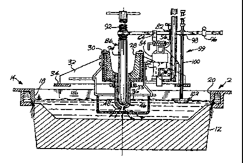
The casting apparatus 2 seen in Figures 1 and 20
is commonly retractably mounted at one side of a pit (not
shown), as are the trough 4 and the basic rack mounted
control apparatus 6; and to start each casting procedure,
first the casting apparatus 2 and then a composite of the
trough 4 and the control apparatus 6, is swung into a
horizontal over the pit. Then, at the conclusion of the
procedure, each is swung back in reverse order for access to
and removal of the casting from the pit. In the pit,
CA 02229932 2005-10-03
74713-10
19h
meanwhile, a platen 8 is mounted on a hydraulic ram or other
elevator means 10 to be raised and lowered vertically of the
pit, and the platen in turn has a series of bottom blocks 12
relatively upstanding thereon for engagement with the
casting apparatus 2 when the assembly is disposed in a
horizontal over the pit.
The casting apparatus itself is conventional in
CA 02229932 2005-10-03
74713-10
19b
operable at the commencement of the fill stage of the
casting operation to preposition the set of valve closure
devices at positions in which the respective valve closure
devices admit the molten metal to the respective sumps
corresponding thereto in amounts that are varied
commensurate with the distance lying along the line of valve
openings between each of the valve openings and a vertical
through the one end of the trough so that as the upper
surfaces of the respective molten metal columns escalate up
the axes of the cavities toward the sensor devices
corresponding thereto during an initial phase of the fill
stage of the casting operation, the upper surfaces of the
respective molten metal columns establish a state of
substantial equilibrium with one another at an intermediate
elevation between the tops of the blocks and the start-up
elevation for the run stage of the casting operation,
control means including a control device operatively
interconnectable with each of the respective sensor devices
and the respective first and second carrier means
corresponding thereto when the upper surfaces of the
respective molten metal columns establish a state of
substantial equilibrium with one another at the intermediate
elevation, to transmit to the respective valve closure
devices corresponding thereto, input signals which are both
a function of the vertical distance between the line of
second carrier means and a reference plane parallel to the
plane with which the relatively lower end openings of the
cavities coincide, and a function of the vertical distance
between the signal generation points of the respective
sensor devices and the upper surfaces of the respective
molten metal columns corresponding thereto, and operating
means for reciprocating one of the sets of first and second
carrier means relatively transverse the line thereof to
impose a desired value on the rate at which the upper
CA 02229932 1998-04-07
WO 97/07912 PCT/US96/13247
nature, and for ease of illustration, it is represented by
a series of the open ended molds 14 with flanged rims
thereabout commonly used in the apparatus. The molds 14
are spaced apart on vertical axes 16, and at their axes,
5 they have shallow, rectangularly shaped, open ended
cavities 18 therein which in turn have coplanar relatively
upper end openings 20 at the top thereof and coplanar
relatively lower end openings 22 (Figures 7 - 10) at the
bottom thereof. The molds also have annular slots 24, or
10 galleries of spaced holes, circumposed about the relative
ly lower end portions of the cavities, for the discharge
of liquid coolant onto the elongated molten metal bodies
or castings formed in the molds during each casting
procedure. The castings are commonly referred to as
15 ingots.
The trough 4 is open at one end 26 and closed at the
other; and has a double-walled sidewall construction and
a refractory liner 28 seated therein between the sidewalls
thereof. The sidewalls are tapered and gunnel plates 30
20 are secured along the respective sidewalls of the trough
and the liner at the tops thereof. Meanwhile, at its
outsides, the opposing ends of the trough are equipped
with brackets 32 having feet 34 thereon, and the feet are
secured to the top of the casting apparatus to extend the
trough in gantry-like fashion above the relatively upper
end openings 20 of the series of cavities 18, and cross-
wise the longer dimensions of them at the axes 16 thereof.
This leaves areas of considerable size open to either
side of the trough, at the relatively upper end openings
of the cavities. At the axes, moreover, the trough has
openings in the bottom thereof , through both the liner and
the bottom of the trough itself , and refractory downspouts
36 are seated in the respective openings to depend below
the trough into the respective cavities corresponding
CA 02229932 2005-10-03
74713-10
21
thereto in the casting apparatus. In addition, the
downspouts also depend within a series of sleeves 38 that
depend from the underside of the trough and the respective
sleeves are equipped with set screws for securing the
downspouts to the trough. Meanwhile, a hanger 40 is
suspended from the sides of the trough at each downspout
and a frame 42 is removably suspended in turn from the
hanger, with a perforated sock 44 suspended in turn on it,
at an elevation below the bottom of the respective
downspout, to filter and aid in distributing the molten
metal to the respective cavity in conventional fashion.
At the inside thereof, each downspout is cylindrical,
but at the bottom thereof, each has a hemispherical nozzle
46 therein which in turn has an opening 48 at the bottom
thereof for the discharge of molten metal to the cavity
corresponding thereto. In each casting procedure, the
respective openings 48 in the nozzles of the downspouts
form valve openings that are spaced apart from one another
in a line extending along a parallel to the bottom of the
trough, and are in registry with the relatively upper end
openings 20 of the respective cavities in the casting
apparatus. Further reference will be made to this line,
as well as to the plane occupied by the relatively lower
end openings 22 of the cavities in the casting apparatus.
Referring now to Figures 1 - 19 in particular, it will
be seen that at its right-hand side in Figures 7 - 10, and
at the left-hand side thereof in Figure l, the trough has
a shelf 50 secured thereon between the brackets 32 at the
opposing ends thereof. A hood 51 is also mounted over the
shelf, but the hood is largely omitted to reveal that
portion of the assembly therebelow in the various views.
In particular, at spaced locations on the shelf, a pair of
machine jacks 52 is mounted upright thereon to form
elevator means for the caps 54 thereof. An elongated
CA 02229932 1998-04-07
WO 97/07912 PCT/LTS96/13247
22
hollow rack 56 is mounted in turn on the caps 54 of the
jacks, and in a parallel to the line of valve openings 48.
Below the rack, worm gears 58 are engaged with the linear
actuators ( not shown ) of the respective jacks , and a shaft
59 is extended along a parallel to the rack, in pillow
blocks 60, to interconnect with and drive the respective
actuators through the respective worm gears corresponding
thereto. A reversible electrical motor 61 is mounted in
turn on the nearer end wall of the hood 51 in Figure 1,
and is flexibly coupled to the shaft to complete the drive
train for the jacks, there also being a flexible coupling
at the opposing end of the shaft where it interconnects
with the worm gear 58 for the more remote jack. The
rotation of the motor dictates the movement of the
respective jacks, and depending on the direction of
rotation, the caps 54 of the jacks may be raised or
lowered relative to the plane with which the relatively
lower end openings 22 of the cavities in the casting
apparatus coincide. The respective jacks can also be
expected to travel up and down a prescribed distance for
each turn of the motor 61, so that by controlling the
rotation of the motor and the shaft 59 connected to it,
the travel of the jacks and the direction thereof can be
controlled in turn.
Laterally opposed to the trough and on top of the
rack, .at each casting station, is a flat rectangular
housing 62 and a U-shaped saddle 64 mounted in turn at the
top thereof . The respective housings 62 provide cases for
a series of trigger devices 66 employed in each casting
procedure, and the respective saddles 64 provide gimbals
for a series of balance beams 68 which are pivotally
mounted in the respective gimbals between pairs of hard
metal points 70 adjustably mounted in the uprights thereof
(Figure 14). The respective pairs of points engage in
CA 02229932 2005-10-03
74713-10
23
turn in conical sockets formed at the opposed ends of hard
metal cylinders 72 disposed thereopposite in the respec-
tive beams. The respective trigger devices 66 (Figures 5
and 6) comprise L-shaped triggers 74 which have stops 76
upstanding about the horizontal legs thereof, and which
are slideably engaged in the respective housings crosswise
of the rack and the trough, with coiled springs 78 caged
about the horizontal legs thereof, between the stops and
the right-hand endwalls of the housings in Figures 5 and
6, to yieldably bias the respective triggers in the
relatively left-hand directions thereof. The triggers
also have conical detents 80 in the upper sides of the
relatively right-hand ends thereof, which engage with
wide-handled screws 82 on the respective balance beams
corresponding thereto, to releasably detain the rotary
actuators of the respective beams against movement in the
downward direction thereof during the initial phase of the
fill operation.
The respective balance beams 68 have a rectangularly
cross sectioned built up construction which is solid at
the right-hand outboard end portions thereof in Figure 1,
and slotted at the left-hand outboard end portions thereof
in Figure 1. The beams are seated in the respective
gimbals 64 corresponding thereto, moreover, so that the
left-hand outboard end portions thereof cantilever above
the left-hand open areas of the cavities, whereas the
right-hand outboard end portions of the respective beams
cantilever above the trough and the respective downspouts
36 depending therefrom. The right-hand outboard end
portions are also equipped with yokes 84 at the ends
thereof, and the yokes in turn have the respective valve
closure devices 86 of the assenibly pivotally suspended
therefrom to depend in the respective downspouts
therebelow, and in loose engagement with the nozzles 46
at the bottoms
CA 02229932 2005-10-03
74713-10
24
thereof for purposes of being reciprocated between
variable positions in which the molten metal in the
downspouts is admitted to the respective cavities there-
below at variable f low rates commensurate with the
respective positions. The respective yokes 84 are also
adapted so that the respective valve closure devices 86 are
removably mounted on the yokes. As seen in Figures 3 and
4, the respective yokes have grooves in the tops thereof,
along diameters coincident with the vertical axes of the
downspouts corresponding thereto, and threaded nuts 88
with pairs of diametrically opposed trunnions 90 thereon,
are saddled in the respective grooves at the trunnions so
as to be removable from the respective yokes, but never-
theless have a limited amount of rotary action available
to them about the axes of the trunnions. The nuts 88 in
turn have threaded rods 92 threadedly engaged therein,
with sockets in the bottoms thereof , and cross bars at the
tops thereof, and suspended on the rods, coaxial there-
with, are elongated valve closure pins 94 with reduced
diameter necks at the tops thereof which insert in the
sockets of the respective rods and are secured to the rods
by pairs of set screws on opposing sides thereof. The
bottoms of the pins are hemispherical to complement the
insides of the nozzles 46 of the
downspouts, and the pins 94 are made of a ceramic material
and sized so that when inserted in the nozzles, annuli are
formed between the respective pins and the respective
nozzles, through which the molten metal can escape to the
cavities therebelow. However, when sufficiently downward-
1y inserted in the downspouts to bottom at the openings 48
of the nozzles, the pins terminate the flow of molten
metal altogether. The extent to which the pins extend
into the nozzles otherwise, and throttle the flow there-
through, depends of course, on the elevations of the
CA 02229932 1998-04-07
WO 97/07912 PCT/CTS96/13247
right-hand ends of the respective balance beams, and the
nuts 88 mounted thereon, as well as the combined lengths
of the pins and rods below the nuts. These lengths can be
- varied by rotating the respective rods 92 in the nuts, up
5 or down, using the bars as handles for the purpose.
The slots in the left-hand outboard end portions of
the respective balance beams have bulkheads arranged
crosswise thereof. One bulkhead 96 in the slot of each
beam is slidable lengthwise of the respective slot, then
10 releasably attachable to the beam, to form an adjustable
counterweight for the left-hand outboard end portion of
the respective beam. Another is fixed to the outboard end
of the slot to carry a screw for fine tuning the ballast
provided by the counterweight; and a third 98 is pivotally
15 mounted in the slot, inboard of the first, with a hole
therethrough for the sensor device 99 of the respective
beam. An elongated rod 100 with a float 102 at the bottom
thereof is fixedly engaged in the hole with set screws to
extend both above and below the beam on an imaginary line
20 which is vertically upstanding in the cavity therebelow,
and adjacent the center of the open area at the top
thereof, when the respective beam is horizontally dis-
posed. The float 102 is broadly dimensioned, flanged,
and sufficiently ballasted to yieldably bias the
25 left-hand outboard end portion of the respective beam to
rotate in the direction of the cavity and the relatively
lower end opening 22 thereof . The rod 100 is sufficiently
elongated below the beam, moreover, that when the assembly
is devoid of molten metal and the rack 56 is in the
bottom-most position thereof, the rod and float depend
well below the relatively lower end opening of the cavity.
The corresponding pin 94 on the right-hand outboard end
portion of the beam engages in the downspout therebelow,
meanwhile, but well above the closure position at the
CA 02229932 2005-10-03
74713-10
26
opening of the nozzle 46 therein.
The upper end portion of the rod 100 above the beam,
has an elongated scale 104 attached upright thereon to
cantilever outboard of the respective rod and cooperate
with a molten metal height indicator 106 mounted abreast
thereof on a post 108 upstanding on the shelf adjacent the
outside edge thereof. In addition, each counterweight 96
has a thumbscrew thereon with which to loosen and tighten
it at its respective positions on the beam corresponding
thereto.
The fourth bulkhead 110 at the inboard end of the
slot in each beam is also fixed, and has one of the wide-
handled screws 82 threaded downwardly therethrough, with
a conical tip 112 at the bottom thereof. The bulkhead 110
is positioned on the respective beam to engage the screw
in the detent 80 of the trigger 74 positioned therebelow,
when the beams are raised and the valve closure devices 86 are
prepositioned before the commencement of the casting
procedure, as shall be explained more fully hereinafter.
The depending length of each screw below the bulkhead 110
can be adjusted, moreover, by screwing the shank of it up
or down in the bulkhead using the handle 113 on the screw.
Each such adjustment operates in turn to vary the arc
length of the angle swung by the respective beam from the
closure position of its pin 94 in the nozzle of the
corresponding downspout, when the tip 112 of the screw
engages in the detent 80 of the trigger corresponding
thereto. Furthermore, when the tip of the screw is
engaged in the detent, the angle of the corresponding beam
dictates the extent to which the pin 94 thereof is
inserted downwardly in its downspout, and therefore, the
extent to which the pin throttles the valve opening of
that nozzle. There is, therefore, an adjustment possible
at both ends of the respective beams for purposes of
CA 02229932 1998-04-07
WO 97/07912 PCT/US96/13247
27
prepositioning the valve devices, as shall be explained.
The respective bottom blocks 12 have conventional
recesses 114 in the tops thereof, and are sized to
telescopically engage in the relatively lower end openings
22 of the cavities in the casting apparatus. Before the
commencement of each casting procedure, the elevator means
1o in the pit are activated to raise the blocks into
engagement with the respective cavities thereabove, and
thereby form sumps 116 within the respective cavities for
the temporary retention of molten metal therein. More-
over, the left-hand outboard end portions of the respec-
tive beams in Figure 1 are raised to space the respective
sensor devices 99 above the tops of the blocks, and the
respective screws 82 on the bulkheads 110 of the beams are
advanced, or retracted, to positions in which, when
engaged with the triggers 74 therebelow, will leave the
balance beams in angular orientations at which the
respective valve devices 86 suspended therefrom will
assume positions within the nozzles of the respective
downspouts therebelow at which they will admit the molten
metal to the respective sumps 116 corresponding thereto in
amounts that are varied commensurate with the distance,
lying along the line of valve openings between each of the
valve openings 48 and the open end 26 of the trough, so
that as the surfaces of the respective molten metal
columns formed in the respective sumps during the initial
phase of the fill operation in the casting procedure to
follow, approach the sensor devices corresponding thereto,
the surfaces will establish a state of substantial
equilibrium with one another at an intermediate elevation
between the tops of the blocks and the start-up elevation
for the casting operation. See Figure 7. To engage the
triggers 74 with the respective screws 82 corresponding
thereto, however, the triggers had to be advanced against
CA 02229932 2005-10-03
74713-10
28
the bias of the springs 78 acting thereon, and as a
consequence, when the surfaces of the respective molten metal
columns in the sumps reach the intermediate elevation, the
sensor devices 99 and the beams from which they are suspended,
will be lifted by the surfaces and at the same time, the
springs 78 of the respective trigger devices will drive the
triggers into the retracted positions thereof, thus freeing
the respective sensor devices and beams for control of the
admission of the molten metal to the cavities at the
respective valve openings corresponding thereto. See Figure 8.
At this point, moreover, the rotary actuators 118
constituted by the left-hand outboard end portions of the
respective beams 68 in Figure 1 and the gimbals 64 corresponding
thereto, each become a control device which is interconnected
with the respective sensor device 99 corresponding thereto,
and the respective right-hand outboard end portion of the beam
and the linear portion of the rack 50 corresponding thereto,
to transmit to the respective right-hand outboard end portion
of the beam, and thus the valve closure device 86 thereon,
input signals which will vary the position of the respective
valve closure device, both as a function of the vertical
distance between the gimbal and a reference plane such as the
plane with which the relatively lower end openings 22 of the
cavities coincide, and as a function of the vertical distance
between the bulkhead 98 in the slot of the respective beam,
i.e., the signal generation point of the respective sensor
device 99, and the surface of the respective molten metal
column therebelow. However, as seen in Figure 8, were the
gimbals 64 to remain at the elevation in which they are shown,
relative to the plane of the relatively lower end openings of
the cavities, the surfaces of the respective molten metal
columns taking on still higher elevations in the sumps
thereafter, would quickly elevate the floats and in turn the
signal transmission points 98 of the respective
CA 02229932 1998-04-07
WO 97/07912 PCT/US96/13247
29
sensor devices, to the extent that the pins would bottom
out in the nozzles in the respective downspouts, and close
off the flow of molten metal therethrough.
According to our invention, therefore, when the
surfaces of the respective molten metal columns reach the
' intermediate elevation and the beams become operational,
we activate the motor 61 for the rack 56 and drive the
rack upwardly at a speed designed to raise the gimbals 64,
and the opposing outboard end portions of the beams in
turn, at a rate adapted on one hand, to dictate the rate
at which we want the surfaces of the respective molten
metal columns to continue to escalate up the axes of the
cavities in the direction of the start-up elevation from
the intermediate elevation, and on the other hand, to
raise the elevation of the signal transmission points 98
of the respective sensor devices at a rate sufficiently
commensurate therewith to render the input signals
transmitted to the respective right-hand outboard end
portions of the beams by the rotary actuators 118 opposed
thereto, substantially consistent with the rate we have
imposed on the surfaces themselves. In this way, the
surfaces can be made to approach the start-up elevation in
a relatively quiescent condition and at a speed entirely
of our own choosing. See Figure 9.
Furthermore, at the start-up elevation, we have
several options available to us. We may deactivate the
motor 61 and cease raising the rack 56, and at the same
time, activate the elevator means 10 in the pit, to lower
the blocks and begin the casting operation at an operating
elevation corresponding to the start-up elevation. Or we
may continue to elevate the rack after activating the
elevator means in the pit, to raise the elevation of the
surfaces above the start-up elevation, and then reverse
the motor for the rack so as to lower the elevation of the
CA 02229932 2005-10-03
74713-10
surfaces to an operating elevation of our choice, after
overfilling the cavities. See Figure 10 in this connec-
tion wherein it will be seen that the blocks 12 have been
lowered below the casting apparatus, the discharge of
5 liquid coolant has begun, and yet the surfaces of the
respective molten metal columns are well above what will
become the operating elevation for the casting operation
once the rack is lowered to lower the surfaces in turn.
In fact, having completed the fill in this fashion; the
10 surfaces may be lowered to elevations in which they
surround the valve openings 48 of the nozzles, but are
disposed at an elevation consistent with "low head"
casting practice.
As explained earlier, moreover, the rack 56 may also
15 be used to relocate the operating elevation for the
casting operation, when the casting speed is changed from
one portion of the operation to another. And of course,
the rack may be used to relocate the elevation of the
surfaces even when a casting operation is conducted at one
20 speed, such as to raise the surfaces to a higher operating
elevation after casting has been commenced at a relatively
lower start-up elevation.
For a procedure to be entirely successful, the floats
102 must have the same geometry, and must be yieldably
25 biased downwardly into the molten metal columns at the
same downward force. That is, the assembly must be
dynamically balanced before each procedure is begun.
A further feature of our invention lends itself to
assuring that there is such a dynamic balance in the
30 assembly. As indicated, the valve closure devices 86 may be
lifted away from the yokes 84 prior to a casting proced-
ure, and preheated before being returned to the yokes for
the procedure itself. However, the preheating step risks
that the arc lengths given the beams in calibrating the
CA 02229932 2005-10-03
74713-10
' 31
bias on them, will be lost when the valve closure devices
are returned to the yokes, and in any event that the arc
lengths will be altered from one casting procedure to the
next, when the valve closure devices are repeatedly removed,
preheated and returned to the yokes.
Figures 11-19 show a modification designed to
enable us to check the accuracy of the respective arc
lengths from one casting procedure to the next, or in any
event, to quickly restore them to a desired level of
accuracy. They also show a different trigger device 119 and
two additional modifications which enable us to incorporate
an electronic controller 120 into the assembly for the
overall control of the various operations in each casting
procedure, including aborting a casting procedure in any one
or more of the cavities when desired. However, the arc
length calibration feature will be explained first, it being
understood in the meantime that the trigger 121 in the
device 119 operates in the same fashion as the trigger 74 in
Figures 5 and 6 insofar as prepositioning the valve devices
is concerned.
Referring now then to Figures 11-16 and 19 in
particular, it will be seen that the bulkheads 122 in the
beams have pairs of screws 124 and 126 threadedly engaged
therein, to be extended downwardly of the respective beams,
or retracted upwardly thereof. The right-hand screws 126 in
each pair of screws are downwardly extended to greater
lengths than the left-hand screws 124, moreover, and all of
the right-hand screws are extended the same length to serve
as a reference with which to confirm or recalibrate the
lengths of the valve closure devices 86 after they have been
preheated and returned to the yokes. That is, after the
beams have been calibrated as to bias, and after the valve
devices have been removed, preheated and returned to the
CA 02229932 2005-10-03
74713-10
32
yokes, but before the left-hand screws 124 of the respective
bulkheads have been engaged with the triggers 121 of the
respective trigger devices 119, to preposition the valve
closure devices, the triggers 121 are extended to the far
right and engaged with the tips of the right-hand screws
126, either to confirm the lengths of the valve closure
devices, or to enable one or more of the valve devices to be
adjusted in length at the handles thereof, so that when the
preliminary procedure is completed, all bottom the same in
the nozzles of the downspouts therebelow, before the trigger
engagement operation of Figures 5-7 is undertaken. Once all
bottom the same in the nozzles, the respective triggers are
released from the right-hand screws, and are withdrawn under
the bias thereon to positions in which they underlie the
tips of the left-hand screws 124. They are then engaged with
the left-hand screws, at the differing lengths thereof to
give the respective beams the arc lengths needed to vary the
inflow of metal to the respective cavities during the
initial phase of the fill operation. Afterward, when a
second casting procedure is undertaken, the triggers can be
engaged once more with the right-hand screws to confirm or
recalibrate the setting of the valve closure devices, and
again before using the left-hand screws to preset the beams
for the fill operation. The same is also true for each
casting procedure undertaken thereafter.
Turning now to the use of the electronic controller
120 in the assembly, the triggers 121 shown in Figures 11-19
are each housed in a case 128 having two parts 130 and 132
(Figure 16) which are superposed one on top of the other to
define an elongated slot 133 (Figure 1.3) therebetween which
slidably accommodates the respective trigger. The upper
surface of the lower part 132 has an elongated groove 134
therein defining the bottom and sides of the slot. The upper
CA 02229932 2005-10-03
74713-10
' 33
part, meanwhile, defines the top of the slot, but both the
bottom of the groove and the opposing lower surface of the
upper part, have elongated recesses 136 and 138 therein which
oppose one another vertically of the slot. A pair of short
posts 140 and 142 is upstanding in the groove 134, one 140 at
the left-hand end of the recess 136, and the other 142
adjacent the nearer sidewall of the groove, and more midway
of the same. The trigger 121 itself is elongated, flat and
rectangularly cross sectioned, and has a handle flanged to
the left-hand end thereof. An oblong recess 144 adjacent the
right-hand end of the trigger provides a decent for the
engagement of the trigger with either of the screws 124 and
126. An elongated slot 146 in the body of the trigger, more
adjacent the left-hand end thereof, provides means whereby a
coiled spring 148 can be caged within the recesses 136 and
138, to yieldably bias the trigger to the retracted position
thereof when it disengages from the screws. The spring 148 i~
an elongated coiled spring with hooks at its respective ends.
The left-hand hook is engaged about the post 140 in the
recess of the lower part, and the right-hand hook is engaged
in a hole 150 in the body of the trigger adjacent the right-
hand end of the slot therein. See Figures 11-13 and 19. An
elongated cutout 152 in the proximal sidewall of the trigger
provides accommodation for the additional post 142 in the
groove 134 so that when the trigger is reciprocated in the
slot, the post operates as a stop, preventing it from
escaping from the slot at either end thereof.
At the interface between the two parts 130, 132 of
the case 128 and laterally offset from the slot 133, the
opposing surfaces of the two parts have generally
rectangularly shaped recesses 154 and 156 therein, with
head-like extensions at the left-hand ends thereof. In
addition, the recess 154 in the surface of the lower part
CA 02229932 1998-04-07
WO 97/07912 PCT/US96/13247
34
has an oblong hole 158 in the right-hand end thereof, and
the hole opens to the underside of the case, as best seen
in Figure 17. When the two parts are sandwiched together
to form the case, a microswitch 16o with a pair of prongs
162 on one end thereof, and a button contact 164 with an
opposing leaf spring contact 166 outstanding on the
relatively inboard side thereof, is screwed onto the
bottom of the recess 154 and captured in the chamber
formed by the recesses, there being bolts and threaded
l0 holes in the four quadrants of the respective parts for
purposes of securing them together in the sandwich.
The microswitches 160 are electrically interconnected
with the controller 120 through leads 168 (Figure 1) with
female receptacles (not shown) thereon which are passed
upwardly through the holes 158 and engaged with the male
prongs 162 of the respective switches before the switches
are mounted in the recesses. Meanwhile, the leaf spring
contacts 166 of the respective switches have rollers 170
on the remote ends thereof which are biased by the leaf
springs on the contacts to ride along the right-hand
sidewalls of the triggers. See Figure 18. The sidewalls
have elongated cutouts 172 therein, however, and the
cutouts are positioned to receive the rollers when the
respective triggers are extended for engagement with the
left-hand screws 124 on the beams. When the rollers so
engage with the cutouts under the bias of the leaf springs
of the contacts, the contact between the leaf spring
contacts and the button contacts 164 on the bodies of the
switches is lost. However, when the triggers are returned
to the retracted positions thereof in the cases, under the
bias of the springs 148 therewithin, the rollers 170 once
again return to the sidewalls of the triggers against the
bias of the leaf springs. This restores contact between
the leaf spring contacts and the button contacts, and
CA 02229932 1998-04-07
WO 97/07912 PCT/LTS96/13247
accordingly, the switches can be said to have two posi-
tions, one when contact is broken and the other when
contact is restored.
The controller 120 is electrically interconnected with
5 the motor 61 for the rack through a further lead 174, and
' when the left-hand screws 124 are engaged with the
respective triggers 121 at the detents 144 thereon, the
open position of the switches with the rollers 170 in the
cutouts 172 tells the controller that the floats are
10 raised so that the casting procedure can be commenced.
The controller may then introduce molten metal to the
entry end 26 of the trough to begin the procedure, and
subsequently, when the screws 124 and triggers 121 are
disengaged from one another by the rising metal in the
15 cavities, the closed position of the switches with the
rollers 170 on the sidewalls of the triggers tells the
controller that the beams are in control of the fill
operation and that the motor can be operated to elevate
the gimbals 64 and enable the fill operation to remain
20 under the control of the beams.
A still further lead 176 between the controller and
the elevator means 10 for the platen, enables the con-
troller to activate the elevator means when the surfaces
of the respective molten metal columns reach the
25 start-up elevation for the casting operation.
Given a programmable controller, the controller 120
may also provide for overfilling the cavities, as in
Figure 10, and for any other variation in the use of the
invention which is desired for the respective fill and
30 casting operations. Likewise, the controller may provide
for changing the speed at which the platen is lowered
relative to the casting apparatus, and restarting the
motor to relocate the gimbals at a level in which the
beams will control the molten metal flow commensurate with
CA 02229932 1998-04-07
WO 97/07912 PCT/LTS96/13247
36
the new speed. So too, the controller 120 may provide for
the gimbals being located at different elevations from one
casting procedure to another, when the cross section of
the respective cavities is changed between casting
procedures.
With each procedure fully automated in this fashion,
we may sit at a console ( not shown ) and monitor the entire
procedure through the controller. Moreover, should we
choose to abort a procedure, or to terminate it premature-
1y, or to terminate the flow to one or more cavities, we
may do so through a further feature of the invention shown
in Figures 11 - 13. As seen in those Figures and in
Figures 14 - 19 as well, the gimbals 64 are mounted on the
housings 128 of the respective trigger devices 119
adjacent the left-hand ends thereof. The remote sides of
the housings have platforms 178 extending outboard
therefrom, on the rack, and pneumatic cylinders 180 are
installed upright on the platforms with props 182 at the
centers thereof to be elevated by the cylinders. Addi-
tionally, between the gimbals and the bulkheads 122 for
the screws 124 126 on the right-hand outboard end portions
of the beams, the beams have L-shaped tongues 184 can-
tilevered laterally outwardly therefrom above the props
182 of the pneumatic cylinders. The controller 120 has a
lead 185 to a signal conversion device (not shown) which
is interposed between it and the respective cylinders, and
pneumatic transmission lines 186 are interposed between
the conversion device and the respective cylinders to
enable us to abort a casting procedure, or the flow to one
or more cavities, when we choose to do so at the console.
That is, by activating the appropriate cylinder or
cylinders 180 to elevate the corresponding prop or props _
182 into abutment with the corresponding tongues 184 on
the beams, we bias the beams to rotate against the bias of
CA 02229932 2005-10-03
74713-10
' 37
the ballast in the floats, and in the direction of the valve
closure devices, to close the corresponding nozzles to flow
therethrough.
The rack 56 is hollow to enable most of the
respective electrical and pneumatic leads to be passed
therethrough from one casting station to the next.
In Figure 20, we have illustrated an electro-
pneumatic version of our invention which employs an
electronic controller 188 and electrically powered non-
contact sensors 190 on the rack. The version is shown in the
context of a single casting station, but it will be
understood that a multiplicity of stations is commonly
employed, and also, regardless of the number, only the single
programmable logic controller (PLC) shown at 188 is needed to
service them. Now, however, the valve closure device 192 for
the downspout 194 at each station is suspended from a balance
beam 196 which is pivotally mounted in a gimbal 198 supported
upright on a shelf block 200 that is secured to one side of
the trough 202 at the station and interconnected with the
shelf blocks at the other stations by a hollow wireway 204.
Though ballasted, each beam 196 is biased to close the nozzle
206 of the respective downspout corresponding thereto, and a
bellows motor 208 is interposed between the shelf block for
the beam and the relatively left-hand outboard end portion
thereof which is cantilevered over the trough and carries the
valve closure device 192 for the respective nozzle.
Furthermore, the sensor devices now take the form of
inductive proximity sensors 190 which are fixedly suspended
from a hollow rack 210 that is spatially offset from the
wireway 204, but like the wireway, disposed on a parallel to
the line of valve openings in the trough and the plane with
which the relatively lower end openings 22 of the cavities 18
of the molds 14 in the casting apparatus 2 coincide.
CA 02229932 1998-04-07
WO 97/07912 PCT/US96/13247
38
The rack is now supported, moreover, on machine jacks 212
which have their own reversible motors 214 at the bottoms
thereof, and in addition, potentiometers 216 connected
with the linear actuators or drivers thereof . The respec-
tive sensors 190 are suspended by hollow tubing 217, and
are electrically connected by cables 218 through the
hollow of the rack to separate electrical processing units
219 which are labeled as "sensor electronics" and convert
the frequency signals from the respective sensors into
surface elevation signals 220 which the electronic
controller 188 can understand. The power for the respec-
tive sensors is supplied at 221 to the respective sensor
electronics units thereof , and at the other side of Figure
20, the controller 188 is electrically interconnected at
222 with the potentiometers 216 on the actuators of the
respective jacks, to receive the signals therefrom
indicating the elevation of the respective actuators
relative to the plane of the relatively lower end openings
22 of the cavities in the molds. The controller is also
electrically interconnected at 224 with the motors 214 of
the respective jacks, and at 226 with a user interface 228
for an operator of the assembly.
The controller 188 is electrically connected at 230
moreover, with a separate air pressure controller 232 at
each casting station, wherein the controller's electrical
signals are converted into corresponding pneumatic
signals for the bellows motor 208 at that station. Pres-
surized air is supplied to the respective air pressure
controllers at 234, and each air pressure controller uses
the pressurized air to dictate fluid pressure signals 235
for the respective motor 208 thereof that reflect the
electrical signals given it at 230. It also transmits
them through what is now more of an "airway" than a
wireway at 204, given that the signals 235 are pneumatic
rather than electronic in character. Given the arrange-
CA 02229932 1998-04-07
WO 97/07912 PCT/US96/13247
39
ment shown, moreover, the electronic controller 188 can
sense the elevation of the rack drivers relative to the
plane of the relatively lower end openings of the
cavities, can receive and understand the respective
signals from the sensors 19o indicating the elevation of
the surfaces of the respective molten metal columns in the
cavities, and with appropriate code, can compare and
integrate the respective signals and transmit its wishes
to the air pressure controllers for the bellows motors at
the respective casting stations, and in addition, its
wishes for the motors of the jacks for purposes of raising
and lowering the rack.
The codes for its transmissions to the air pressure
controllers and its transmissions to the motors and
actuators, i.e., the "driver" of the rack, are shown
schematically in Figures 21 - 23. These show the codes for
the casting procedure itself, however, and it should be
mentioned in advance that before a procedure is
undertaken, a calibration jig (not shown) is placed in
each cavity, and programming ( not shown ) in the controller
scans the position signal 222 from the rack driver,
compares it to a previously set calibration value, and if
they are not equal, sends a signal to the rack driver
motors 214, causing them to move the rack to the
calibration position. Meanwhile, the rack mounted
induction sensors 190 detect the calibration jigs and send
the usual frequency signals to the respective sensor
electronics units 219 thereof, which convert the signals
in turn to elevational signals that the controller can
understand. Though the sensors can measure elevation over
a wider range, to maximize their accuracy, we maintain
them at substantially a fixed distance from the surfaces
of the respective molten metal columns therebelow, using
the bellows motors and the rack, but with a range of
tolerance provided at that distance, so that the rack is
CA 02229932 2005-10-03
74713-10
not continually in use to idealize the vertical distance
between the signal generation points of the respective sensors
and the surfaces therebelow. See USP 5,339,885 in this
connection. For example, the controller may be programmed to
5 maintain the signal generation points of the respective
sensors at an optimal distance of, say, 1 inch from the
surfaces of the molten metal columns therebelow, but with a
tolerance of 0.1 inch to either side of that distance. This
range of tolerance is commonly referred to as the "dead band"
10 or "dead band area" for the elevation of the respective
sensors. At this stage in the calibration then, the controller
internally "zeros" out the "dead band", say, at 1 inch, and
retains this calibrated reading before the jigs are removed.
Meanwhile, the controller 188 also sends a signal to the
15 respective air pressure controllers 232 which each convert it
to a pressure signal for the respective bellows motor thereof
that is designed to move the balance beam corresponding
thereto to a specified calibration position. Thereafter, each
valve closure device is moved up or down until it "seats"
20 lightly at the bottom of its respective nozzle.
Once calibration has been accomplished, the
controller sends a new signal to the respective air pressure
controllers which in turn send a new air pressure signal to
each bellows motor causing it to position its respective valve
25 closure device at a preset "free fill" position for the start
of the casting procedure. The controller also reads the
position signal from the rack driver, compares it with a
preset initialization value, then sends a signal to the rack
driver motors telling them to move the rack to a start
30 position for the cast. The respective preset "free fill"
positions for the valve closure devices are determined in a
trial and error sequence during the initial set up of the
assembly, and therefore, when molten metal is introduced to
the trough at the entry end thereof, it flows through
CA 02229932 2005-10-03
74713-10
41
the downspouts around the valve closure devices therein and
into the cavities below in a manner designed to
substantially stabilize the surfaces of the respective
molten metal columns in the sumps at an intermediate
elevation between the tops of the blocks and the start-
up elevation for the casting operation. Then, as the
surfaces continue to rise in a horizontal and reach the
"zero" point in the dead band for the sensors, as
indicated by the converted signals from the respective
sensors, the controller begins to sum the position signal
of the rack with the value of the converted sensor
signals, and compares this summed value in turn with a
predetermined time/position ramp or rate desired for the
escalation of the surfaces during the remainder of the
fill operation. See Figure 21. If this summed value does
not equal the value for that particular moment on the
ramp, the controller will increase or decrease its signal
230 to the air pressure controllers by way of adjusting
the air pressure therein to cause the respective bellows
motors thereof to adjust their respective valve devices in
turn, either to increase or decrease the flow of metal to
the respective cavities, thus imposing a desired value on
the rate at which the respective surfaces continue to
escalate up the axes of the cavities at this stage in the
casting procedure.
When the surfaces of the respective molten metal
columns rise to a point, however, at which they move out
of the range of tolerance or "dead band area" allotted to
the distance between the surfaces and the respective
signal transmission points of the sensors, as indicated to
the controller by the signals from the respective sensor
electronics units, the controller will send a signal 224
to the rack driver motors causing them to move the rack
and thus the sensors thereon, back within the dead band
thereof, for example, back within a range of 1 inch plus
CA 02229932 2005-10-03
74713-10
42
or minus 0.1 inch. Typically, the controller will scan
the converted signals from the respective sensors, and use
either the highest, the lowest or the average value
therefrom, in determining whether to power the rack driver
motors or not. See Figure 22.
Alternatively, as the surfaces of the respective
molten metal columns continue to rise in a horizontal and
reach the "zero" point of the dead band, as indicated by
the converted sensor signals from the respective sensor
electronics units, the controller may be programmed
instead to send a signal 224 to the rack driver motors
causing them to power the rack driver and thus the rack
and the mounted sensors thereon, in the upward direction.
Thereafter, through monitoring the position signal 222
from the rack driver, the controller can raise the rack
along any time/position ramp desired for the rate at which
the surfaces escalate up the axes of the cavities. In the
meantime, when the sensors rise with the rack, and the
surfaces of the respective molten metal columns fall out
of the "zero" point of the dead band, as indicated by the
converted signals from the respective sensor electronics
units, the controller will send a signal 230 to the
respective air pressure controllers which is designed to
generate that air pressure signal in the respective
bellows motors thereof which is needed to make the input
signals to the respective valve closure devices thereof
consistent with the desired ramp for the rate at which the
surfaces escalate up the axes of the cavities. See Figure 23.
When the surfaces of the respective molten metal
columns have reached the start-up elevation which was
programmed into the controller, and which is indicated by
the position signal from the rack driver, summed with the
converted signals from the sensor electronics, the
controller may thereafter maintain the operating elevation
for the casting operation by monitoring the summed
CA 02229932 1998-04-07
WO 97/07912 PCT/LTS96/13247
43
signals, and if the summed value does not equal the value
necessary to maintain the operating elevation, the
controller will send a signal 230 to the air pressure
controllers designed to restore the surfaces to the
desired operating elevation. Meanwhile, if the surfaces
fall out of the "dead band area" for the sensors, and as
indicated by the converted signals from the respective
sensor electronics units, the controller will send a
signal to the rack driver motors causing them to relocate
the rack and the sensors back within the dead band area.
once again, in doing so, the controller will commonly scan
the converted signals to use either the highest, the
lowest or an average value in determining whether to send
a power signal to the rack driver motors or not.
Alternatively, the controller may employ only the
bellows motors to maintain the surfaces at a desired
operating elevation for the casting operation.
As indicated earlier, the balance beams 196 for the
respective valve devices 192 are biased to close the
respective valve openings in the trough, and the bellows
motors 208 are positioned under them to raise the respec-
tive beams against the bias to open the valves, or to
relax and allow the valves to close in turn. However,
when molten metal flows through the bottoms of downspouts,
it sometimes creates a suction on the pins of the
respective valve devices, tending to draw them into the
valve openings of the downspouts with it and thereby
create a back pressure on the actuators of the bellows
motors. The dampener device incorporated into each motor
in Figure 24 acts to counteract this effect, that is, to
resist relatively low pressure feedback signals which
would otherwise be fed into the pneumatic input signals
from the air pressure controllers.
As seen in Figure 24, each motor 208 comprises a
cylindrical block 236 with a bore 238 in the top thereof
CA 02229932 1998-04-07
WO 97/07912 PCT/US96/13247
44
at its vertical axis. The bottom of the block also has a
cylindrical bore 24o therein, which is annular and
circumposed about the axial bore 236 in the top thereof.
The bore at the bottom is also counterbored at 242, and a
cover 244 is applied to the bore 240, in the counterbore
242 thereof, and another cover 246 is applied to the top
of the block, using machine screws 248. Elastomeric
sealing rings are also used at 250 and 252, about and
below the respective covers.
The top cover 246 is annular, and the opening 254 at
the center thereof has the bladder 255 of the bellows
motor suspended about the perimeter thereof, with a cover
plate 256 thereover which is also annular to accommodate
the linear actuator 258 of the bellows motor. The
actuator in turn has a disk 260 at the bottom thereof,
about the perimeter of which the bladder is secured to
close it at its interior. Below the disk, the bottom of
the bore 238 is slightly swaled, and at the axis of the
device, the bore 238 opens into the bottom of the block
through a threaded hole 262 therein, which is counterbored
about the bottom end thereof, to form a small chamber 264
about the axis between the bottom cover 244 and the hole
262 on the axis of the block. A still smaller hole 266
angles into the chamber from the bore 240, and a slotted
screw 268 is threaded into the hole 262 at a head diameter
less than that of the chamber. The screw in turn has a
narrow diameter hole 270 therethrough at the axis of the
device, which communicates at its upper end with the bore
238, and at its lower end with the slot 272 in the screw
and the chamber itself.
The block is flanged at the bottom thereof, and an L-
shaped passage 274 is formed at the periphery of the block
on one side thereof. The passage opens at the flange and
communicates at its top with the top of the annular bore
240 of the block. A valve seat 276 is formed at the top
CA 02229932 1998-04-07
WO 97/07912 PCT/US96113247
of the passage so that a set screw 278 can be threadedly
inserted in the passage from a socket 280 in that portion
of the block above the passage. The screw is engaged in
' the valve seat when the dampener device is out of use, for
5 example, when the assembly is undergoing shipment, tilted
' up or otherwise not disposed in a vertical condition.
When assembled, oil 281 is charged into the reservoir
provided by the block at the respective chambers 238 and
240 thereof, and the oil in turn also occupies the chamber
10 264 below the bore 238, the hole 266 between the chamber
and the bore 240 , and the restricted hole 270 in the screw
between the bore 238 and the chamber. When the device is
put to use, the lead 235 for the pneumatic pressure signal
from the respective air pressure controller for the
15 device, is attached to the open end of the passage 274 in
the flange of the block. The resulting connection
operates to feed the pneumatic signal to the top of the
oil charge in the bore 240, and the signal is transferred
in turn through the charge to the bladder 255 of the
20 motor. The oil-borne signal then collapses the bladder,
or allows it to expand, depending on the character of the
signal, and this effect is transferred to the disk 260 in
turn, which in turn transfers the signal to the actuator
258, and the actuator in turn to the balance beam 196
25 of the respective casting station. On the other hand,
when the beam transfers a feedback signal to the actuator,
and the actuator in turn to the driven end 260 of the
motor, that signal is resisted by the restriction the
charge 281 encounters at the hole 270 of the screw. As a
30 result, each feedback signal seldom has any effect on the
setting of the valve device in the nozzle 206 of the
corresponding downspout 194.
In figure 25, we have illustrated the fact that each
signal from the electronic controller 188 can be sent by
35 way of a trough mounted wireway 282 to the reversible
CA 02229932 2005-10-03
74713-10
46
electric motor 284 of a linear actuator 286 which is housed
in a case 288 at the respective casting station on the
wireway, and pivotally interconnected with the balance beam
290 for the respective valve closure device at an outboard
point thereon spaced apart from the fulcrum 292 of the
respective beam at the top of the case. However, this is a
less desirable way to deliver the input signals to the
respective valve closure devices, because once again,
electrical leads and electrical components are stationed
directly at the trough 294 and above the heat of the
cavities.