Note: Descriptions are shown in the official language in which they were submitted.
CA 02229962 1998-02-20
TITLE OF THE INVENTION
AN INTERFACE APPARATUS FOR ADAPTING A
GAS FLOW VALVE TO A GAS METER
BACKGROUND OF THE INVENTION
1. Field of the Invention
The present invention relates to the installation of gas flow valves, such as
seismic safety valves, to existing plumbing having a gas meter. More
particularly,
the present invention is directed to a method and apparatus that enables the
installation
of a gas flow valve into existing plumbirig having a gas meter.
2. Description of the Prior Art
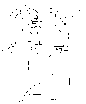
Typical known gas meters have an arrangement as demonstrated in Fig. 1. In
this figure, an inlet pipe 11 is connected through plumbing 12 to a gas meter
10
before the gas flows into a point of use of the gas, for example, a residence.
The
plumbing 12 is connected to the gas meter 10 by a union nut 13. The gas meter
10 is
a known device having such a union nut 13, as well as a union nut 14 at the
outlet of
the gas meter. The union nut 14 is originally connected to a service tee 15.
When
the meter is replaced, the service tee 15 is used to maintain a continuous
flow of gas
through the system by removing the plug end of the tee 15 and inserting a
device into
the end of the tee that is connected to a portable gas tank. This allows
service, such
CA 02229962 1998-02-20
as the replacement of the gas meter 10, to be performed without having to stop
the
flow of gas through the remainder of the gas system.
SUMMARY OF THE INVENTION
The object of the present invention is to provide an easy way of retrofitting
a
generic shutoff valve with existing plumbing having a gas meter. While it
might be
considered that, upon recognizing this desire, one could replumb the
arrangement to
fit the valve, the present inventor has arrived at a solution permitting
simple and rapid
installation of a gas flow valve at the location of the gas meter without
replumbing.
According to one embodiment of the present invention, a gas flow valve is
provided with an outlet and an inlet on one side thereof, each having
respective union
nuts for engagement with the inlet and the outlet of the gas meter,
respectively,
Furthermore, the gas flow valve is provided with an inlet and an outlet at
another
portion thereof for connection with the inlet plumbing and the outlet plumbing
leading
to the residence or other point of use. The inlet and the outlet at the other
part of the
gas flow valve connect with the union nuts of the inlet plumbing and the
outlet
plumbing. In this way, the gas flow valve serves as an interface between the
plumbing serving as the inlet of the gas and the outlet of the gas to the
point of use,
and the gas flow meter.
2
CA 02229962 1998-02-20
In view of the fact that the gas flow valve effectively has two gas inlets and
two gas outlets, one gas inlet is connected with one gas outlet through a
dummy
passage, whereas the actual valving portion is provided in the other passage
between
the other gas inlet and the other gas outlet.
Thus, upon installation of the gas flow valve, with a gas meter having been
previously installed and connected to inlet plumbing and outlet plumbing going
to the
point of use, the gas meter is simply disconnected. Then, the gas flow valve
is
connected to the point where the gas meter was previously connected, with one
gas
inlet and one gas outlet being connected to the inlet plumbing and the outlet
plumbing, respectively. The gas meter is then reconnected by connecting the
gas
meter to the union nuts of the gas flow valve at the other gas flow outlet and
gas flow
inlet of the gas flow valve.
Thus, in effect, the gas flow valve is designed so as to have the same inlet
and
outlet arrangement, with respect to the plumbing, as the gas flow meter.
Furthermore, the gas flow valve is designed to have the same gas flow outlet
and gas
flow inlet arrangement, with respect to the gas flow meter, as the inlet and
the outlet
plumbing. In this way, no plumbing changes are necessary to the existing
plumbing.
The gas flow valve simply has to be installed.
As an alternative to having a gas flow valve which has connections for both
the inlet and outlet plumbing, and connections for both the inlet and outlet
of the gas
3
CA 02229962 2006-03-16
61954-61
flow meter, the gas flow valve could also be provided so as
to simply connect between either the inlet plumbing and the
inlet of the gas flow meter, or the outlet plumbing and the
outlet of the gas flow meter. In this instance, the other
side would have a simple extension or dummy pipe having the
same length or separation as the gas flow valve connected
between the point in the plumbing and the point on the gas
flow meter that were not connected to the valve. Otherwise,
this arrangement could be simply employed and installed
similar to the above-described arrangement.
In instances where a gas flow meter has been
installed at a point having little ground clearance, the
installation might be difficult, in that the meter might not
be capable of being lowered a sufficient amount to allow the
gas valve to be installed. In this case, an S-shaped link
is connected between the inlet plumbing and the inlet of the
gas valve, with the outlet of the gas valve being connected
to the inlet of the gas meter. The gas meter would then
have its other connection, the outlet, connected to the
usual inlet. Alternatively, the S-shaped linking pipe and
the gas valve could be connected between the outlet of the
gas meter and the outlet plumbing going to the point of use.
The invention may be summarized according to one
aspect as a method of installing a gas flow shutoff valve
into existing gas plumbing that is connected to a gas meter,
the existing gas plumbing including a plumbing gas outlet
and a plumbing gas inlet, and the gas meter having a meter
gas inlet connected to the plumbing gas outlet and a meter
gas outlet connected to the plumbing gas inlet, said method
comprising: providing a gas flow shutoff valve comprising a
4
CA 02229962 2006-03-16
61954-61
housing having a valve gas inlet and a valve gas outlet, a
first gas conduit extending between the valve gas inlet and
the valve gas outlet, and a shutoff valve arrangement along
the conduit between the valve gas inlet and the valve gas
outlet, whereby gas flow can be shut off between the valve
gas inlet and the valve gas outlet by activation of the
shutoff valve; disconnecting the meter gas inlet from the
plumbing gas outlet; and connecting the gas flow shutoff
valve between the meter gas inlet and the plumbing gas
outlet by connecting the valve gas inlet to the plumbing gas
outlet and connecting the valve gas outlet to the meter gas
inlet, by providing for the gas flow path between the meter
gas outlet and the plumbing gas inlet to be an open flow
path which has no valve therealong, and without
repositioning the plumbing gas outlet and the plumbing gas
inlet of the existing gas plumbing, such that activation of
the gas flow shutoff valve will shut off the flow of gas
between the plumbing gas outlet and the plumbing gas inlet.
According to another aspect the invention provides
a method of installing a gas flow shutoff valve into
existing gas plumbing that is connected to a gas meter, the
existing gas plumbing including a plumbing gas outlet and a
plumbing gas inlet, and the gas meter having a meter gas
inlet connected to the plumbing gas outlet and a meter gas
outlet connected to the plumbing gas inlet, said method
comprising: providing a gas flow shutoff valve comprising a
housing having a valve gas inlet and a valve gas outlet, a
first gas conduit extending between the valve gas inlet and
the valve gas outlet, and a shutoff valve arrangement along
the conduit between the valve gas inlet and the valve gas
4a
CA 02229962 2006-03-16
61954-61
outlet, whereby gas flow can be shut off between the valve
gas inlet and the valve gas outlet by activation of the
shutoff valve; disconnecting the meter gas outlet from the
plumbing gas inlet; and connecting the gas flow shutoff
valve between the meter gas outlet and the plumbing gas
inlet by connecting the valve gas inlet to the meter gas
outlet and the valve gas outlet to the plumbing gas inlet,
by providing for the gas flow path between the meter gas
inlet and the plumbing gas outlet to be an open flow path
which has no valve therealong, and without repositioning the
plumbing gas outlet and the plumbing gas inlet of the
existing gas plumbing, such that activation of the gas flow
shutoff valve will shut off the flow of gas between the
plumbing gas outlet and the plumbing gas inlet.
According to another aspect the invention provides
a gas flow valve assembly for retrofitting a gas flow
shutoff valve with existing gas plumbing that includes a gas
meter, the plumbing including a plumbing gas outlet and a
plumbing gas inlet, the gas meter including a meter gas
inlet and a meter gas outlet at predetermined positions, and
said assembly comprising: a gas flow shutoff valve
comprising a housing having a first valve gas flow inlet and
a first valve gas flow outlet on opposite sides thereof, a
first gas conduit extending through said housing between
said first valve gas flow outlet and said first valve gas
flow inlet, a shutoff valve arrangement located along said
first gas conduit, a second valve gas flow inlet and a
second valve gas flow outlet on opposite sides of said
housing, and a second gas conduit extending through said
housing between said second valve gas flow inlet and said
4b
CA 02229962 2006-03-16
61954-61
second valve gas flow outlet, said second gas conduit being
an open flow path which has no valve therealong; wherein
said first valve gas flow inlet and said second valve gas
flow outlet are on a first common side of said gas flow
valve and spaced at the same spacing as the predetermined
positions, and wherein said second valve gas flow inlet and
said first valve gas flow outlet are on a second common side
opposite from said first common side with respect to said
housing and also spaced at the same spacing as the
predetermined positions; and wherein said first valve gas
flow inlet and said first valve gas flow outlet are spaced
from each other a distance that is equal to the distance
which said second valve gas flow inlet and said second valve
gas flow outlet are spaced from each other; whereby said gas
flow shutoff valve can be retrofitted between the gas meter
and the existing gas plumbing without repositioning the
plumbing gas outlet and the plumbing gas inlet of the
existing gas plumbing.
According to yet another aspect the invention
provides a gas flow valve assembly for retrofitting a gas
flow shutoff valve with existing gas plumbing that includes
a gas meter, the plumbing including a plumbing gas outlet
and a plumbing gas inlet, the gas meter including a meter
gas inlet and a meter gas outlet, and said assembly
comprising: a gas flow shutoff valve comprising a housing
having a valve gas flow inlet and a valve gas flow outlet, a
first gas conduit extending between said valve gas flow
inlet and said valve gas flow outlet, and a shutoff valve
arrangement located along said first gas conduit so as to be
capable of shutting off gas flow between said valve gas flow
4c
CA 02229962 2006-03-16
61954-61
inlet and said valve gas flow outlet, said valve gas flow
inlet and said valve gas flow outlet being located on said
housing and separated a predetermined distance from each
other; a pipe having a pipe inlet and a pipe outlet, said
pipe inlet and said pipe outlet being separated a
predetermined distance from each other that is the same as
the predetermined distance separating said valve gas flow
inlet and outlet in one direction, and said pipe forming a
second gas flow conduit between said pipe inlet and said
pipe outlet that is an open flow path; and connecting
elements on said valve gas flow inlet and said valve gas
flow outlet and on said pipe inlet and said pipe outlet for
connecting said gas flow valve and said pipe with the
plumbing gas outlet and the plumbing gas inlet and with the
meter gas inlet and the meter gas outlet; wherein said gas
flow shutoff valve, said pipe, and said connecting elements
are capable of being assembled together and positioned
together with the gas meter between the plumbing gas outlet
and the plumbing gas inlet such that activation of said
shutoff valve will shut off the flow of gas from the
plumbing gas outlet to the plumbing gas inlet.
According to a further aspect the invention
provides a gas flow valve assembly for retrofitting a gas
flow shutoff valve with existing gas plumbing that includes
a gas meter, the plumbing including a plumbing gas outlet
and a plumbing gas inlet, the gas meter including a meter
gas inlet and a meter gas outlet, and said assembly
comprising: a gas flow shutoff valve comprising a housing
having a valve gas flow inlet and a valve gas flow outlet, a
first gas conduit extending between said valve gas flow
4d
CA 02229962 2006-03-16
61954-61
inlet and said valve gas flow outlet, and a shutoff valve
arrangement located along said first gas conduit so as to be
capable of shutting off gas flow between said valve gas flow
inlet and said valve gas flow outlet; a curved pipe having a
pipe inlet and a pipe outlet, said pipe inlet and said pipe
outlet being separated a predetermined distance from each
other that is the same as the predetermined distance
separating said valve gas flow inlet and outlet, and said
pipe forming a second gas flow conduit between said pipe
inlet and said pipe outlet that is an open flow path; and
connecting elements on said valve gas flow inlet and said
valve gas flow outlet and on said pipe inlet and said pipe
outlet for connecting said gas flow valve and said pipe with
the plumbing gas outlet and the plumbing gas inlet and with
the meter gas inlet and the meter gas outlet; wherein said
gas flow shutoff valve, said pipe and said connecting
elements are arranged such that if said pipe and said valve
are connected together and connected between one of the
plumbing outlet and said meter gas inlet, and the plumbing
inlet and said meter gas outlet, activation of said shutoff
valve shuts off the flow of gas from the plumbing gas outlet
to the plumbing gas inlet.
BRIEF DESCRIPTION OF THE DRAWINGS
The above and further features and advantages of
the present invention will be
4e
CA 02229962 1998-02-20
further discussed below with reference to the accompanying drawings, in which:
Fig. 1 is a schematic view of a typical arrangement of a gas flow meter;
Fig. 2 is a schematic view of a gas flow valve interface arrangement, showing
some parts separated, according to a first embodiment of the present
invention;
Fig. 3 is a schematic view of a gas flow valve interface arrangement according
to a second embodiment of the present invention; and
Fig. 4 is a schematic view of a third embodiment of a gas flow valve interface
arrangement according to the present invention.
DETAILED DESCRIPTION OF THE PREFERRED EMBODIMENTS
A gas flow meter 10 has a gas inlet 23 and a gas outlet 24. These mating
parts 23 and 24 would, in the prior art system, be connected to the union
nuts, such
as union nuts 13 and 14, of inlet plumbing 11, 12 and outlet plumbing 15.
However,
with the present invention, it is desired to retrofit a gas flow valve to the
point of use
of the gas, as at a residential home, a business or other point where it may
be desired
to be able to shut off the flow of gas either at will or upon certain seismic
or other
activities taking place.
The type of valve 20 could be any suitable valve that is desired to be
retrofitted for purposes of shutting off the f7ow of gas. One particularly
desirable
5
CA 02229962 2006-03-16
61954-61
kind of valve is a seismic safety valve that automatically
shuts off the flow of gas upon the occurrence of a certain
level of seismic activity. One valve of this type is
disclosed in U.S. Patent 5,409,031, and another in
U.S. Patent 6,085,772. Other suitable gas flow valves that
could be adapted for use as in the present invention are
disclosed in U.S. Patents 4,311,171, 4,565,208, 4,475,565,
4,903,720, and 5,119,841.
The gas flow valve 20 according to the present
invention can be any of the above valves, as long as it is
modified to have an appropriate arrangement of gas inlets
and gas outlets in accordance with the following discussion.
That is, the gas flow valve 20 as shown in Fig. 2
has mating parts 21 and 26 corresponding to the mating
parts 23 and 24 of the gas flow meter. As shown in Fig. 2,
they can be provided in the upper surface of the gas flow
valve 20 as installed, assuming the gas flow meter 10
depends from the inlet plumbing 11, 12 and outlet
plumbing 15. Furthermore, the gas flow valve 20 has an
outlet and an inlet at 22 and 25, 22 and 25 being union nuts
corresponding to union nuts 13 and 14 of the inlet
plumbing 11, 12 and outlet plumbing 15.
It is noted that the inlet plumbing 11, 12
includes an inlet pipe 11 and a curved plumbing portion 12
extending to the union nut 13. The outlet plumbing 15
includes a T-shaped member, also known as a service tee.
When a meter is ordinarily replaced, the service tee is used
to supply a continuous flow of gas through
6
CA 02229962 1998-02-20
the system, because the plug end of the tee can be removed. After removal of
the
plug end, a device is inserted into the end that is connected to a portable
gas tank.
This allows the replacement of the gas meter (or other service) to be
performed
without having to stop the flow of gas through the remainder of the gas
system.
As discussed above, the gas flow valve can be a valve as in one of the above-
referenced U.S. patents, but with the following modifications. That is, as can
be
clearly appreciated from this discussion, the valve as shown in Fig. 2 is
required to
have two gas flow inlets and two gas tlow outlets. One inlet and outlet
correspond to
a connection between the inlet plumbing 11, 12 and the mating part or inlet
part 23 of
the gas flow meter 10. Another inlet and outlet of the gas flow valve 20
corresponds
to the connection between the mating part or outlet part 24 of the gas flow
meter 10
and the union nut 14 of the outlet plumbing 15.
As can be clearly appreciated, gas passages extend through the gas flow valve
between the respective inlets and outlets, as illustrated by the arrows in
Fig. 2. In
15 one of these gas flow passages, the valving arrangement is discussed in the
above-
referenced U.S. patents is located. The housings are simply modified to allow
for the
mating parts 21 and 26 and the union nuts 22 and 25 to be located for the
respective
positions of the union nuts 13 and 14 of the inlet and outlet plumbing and the
mating
parts 23 and 24 of the gas flow meter. In other words, the gas flow passage of
20 anyone of these valves is adapted in accordance with the present invention
to have a
7
CA 02229962 1998-02-20
retrofit capability by providing the respective mating parts and union nuts at
locations
corresponding to those for the gas flow meter and the inlet and outlet
plumbing.
When installing the gas flow valve 20 into a prior arrangement as illustrated
in
Fig. 1, the union nuts 13 and 14 connecting to the mating parts 23 and 24 are
loosened so as to drop the meter 10. The meter 10 is lowered and the valve 20
inserted between the meter 10 and the inlet plumbing and outlet plumbing. Then
the
mating parts 21 and 26 are connected to the union nuts 13 and 14,
respectively, while
the mating parts 23 and 24 of the gas flow ineter 10 are connected to the
union nuts
22 and 25. Accordingly, the gas flow valve 20 is easily and quickly connected
into
the existing plumbing without having to replumb, and without having to modify
the
gas flow meter. This advantage, according to the present invention, can result
in
significant savings of costs associated with plumbers when having to install
gas flow
valves, because no inodification of the existing plumbing needs to take place.
A second embodiment according to the present invention is demonstrated by
Fig. 3. This embodiment is essentially similar to that of Fig. 2, in operation
and in
effect, except for the following. That is, the gas flow valve 20 is only
located
between one mating part 23 or 24 of the gas flow meter 10 and one union nut 13
or
14 of the inlet plumbing 12, and outlet plumbing 15. A pipe or sleeve 27,
having a
corresponding mating part 26 and union nut 25, is inserted at the other side
from the
gas flow valve 20 upon installation of the gas flow valve 20, this pipe 27
having the
8
CA 02229962 1998-02-20
same length as the gas flow valve 20. Thus, the same advantages as in the
embodiment of Fig. 2 are achieved. Obviously, the gas flow valve 20 could be
mounted either at the inlet side of the gas with respect to the gas flow meter
10 or at
the outlet side thereof.
Fig. 4 illustrates a third embodiment according to the present invention. This
embodiment is essentially similar to the other embodiments in the provision of
a gas
flow valve 20. However, this embodiment takes into consideration the problem
that
arises in situations where a lack of ground clearance may prevent the lowering
of the
gas flow meter 10 to a sufficient degree to allow the insertion of the gas
flow valve
20 between the union nut 13 and the mating part 23, for example. In this
instance, an
S-shaped link pipe 30 could be providecl. This pipe has a union nut 32
corresponding
to the union nut 13, and a mating part 31 corresponding to the mating part 23.
Thus,
this pipe connects between the mating part 21 of the gas flow valve 20 and the
union
nut 13 of the inlet plumbing 11, 12. The gas flow valve 20, similar to that
illustrated
in Fig. 3, is inserted between the end of the S-shaped link 30 and the gas
flow meter
10, as illustrated and described above. The other mating part 24 of the gas
flow
meter 10 can remain connected to the union 14 of the outlet plumbing 15, with
it
simply being pivoted from its original position to allow for insertion of the
S-shaped
link 30.
Tlus, according to the present invention, the gas flow valve 20 can be
9
CA 02229962 1998-02-20
retrofitted into existing gas flow meter arrangements without having to
replumb such
arrangements. This is achieved by the gas flow valve 20 being adapted to mimic
the
plumbing arrangement and connections of the existing plumbing as described
hereinabove so as to interface between the gas flow meter 10 and the existing
plumbing. This allows for a significant reduction in the costs associated with
the
installation of such gas flow valves 20.