Note: Descriptions are shown in the official language in which they were submitted.
CA 02229992 1998-02-18
W O 97/06756 PCTrUS96/13S14
METHOD AND APPARATUS FOR SOFT TISSUE ENLARGEMENT INCLUDING
MECHANICAL SOFT TISSUE ENLARGER AND VACUUM DOME
Backqround and SummarY of the Invention
There are numerous instAnc~ where persons desire
enlaly~- -nt of the soft tissues in their bodies. One
such instance is for the repl~c~ ?nt of one or both
breasts amputated during a mastectomy in order to restore
physiological symmetry and psychological well-being.
Other instAnc~ are for correction of natural
abnormalities such as dimpling. Still other instAn~-e-~
are for augmentation of physical attributes to improve
cosmetics and self-esteem. These latter soft tissue
enlargements are principally directed to breast
enlaly~ ?nt in females and penis enlargement in males.
Prosthetic implants have been developed for
insertion below the skin. However, the severity of the
potential complications including scarring, implant
rupture, capsular contracture, necrosis and implant
migration as well as the recent adverse publicity thereof
have significantly reduced the desirability of these
implants. Thus, there is a societal need for other means
to obtain soft tissue enlargement.
Some soft tissue enlargements occur naturally.
For instance, during pregnancy, the skin over a woman's
abdom; n~ 1 region enlarges approximately nine times its
previous area to Al- - - - date the fetus without a
proportional decrease in skin thickness. In other words,
the ab~lom; rlAl skin tissue actually enlarges and does not
merely stretch during pregnancy. Similarly, the skin
will expand to ~c~- ~date any growth under the skin.
In the past, plastic surgeons have used this
ph~nl -~on to their advantage to expand skin in order to
~ 30 Af-f- odate prosthetic implants. To conduct this
procedure, the surgeon inserts a balloon beneath the skin
in the area where additional skin is desired. By
progressively exp~n~;ng the balloon, the skin first
stretches and eventually actually grows to acc~ -date
CA 02229992 1998-02-18
W O 97/06756 PCTAUS96/13514
the increased volume underneath it. When the desired
amount of skin is formed, the balloon is deflated and
L~ ved, and the implant is inserted into the cavity left
by the balloon. Similar methods have been used by native
African tribes to enlarge lips, nostrils, and earlobes.
Other surgical techn;ques have used tissue
expansion to achieve other types of soft tissue growth.
For instance, balloons have been successfully expanded
underneath nerves, veins, t~n~on~, and the like to
lC thereby elongate these tissues to repair damage and
alleviate various abnormalities.
A more advanced surgical method is known as
callotasis or limb length~n;ng. This method comprises
cutting the bone about its periphery at the location
where lengthen;ng is desired, leaving the tissues inside
and around the bone intact. Brackets are att~che~ to the
bone on each side of the separation, and the bone
~gr~nts are slowly pulled away from one another while
re~-;ning integral over a period of several months. Not
only does this cause the ~n~ bone to be longer, but
also the soft tissue surrol~n~ing the bone actually grows
to A~ _ _ date the increased limb length. Similar
methods have been used by African native tribes to
lengthen necks for cosmetic purposes.
Each of these above-mentioned apparatuses and
methods requires an invasive surgical t~çhn;que to
Acc~plish the soft tissue ~xp~n~ion~ Invasive
techniques increase the likelihood of the complications
associated with the procedure including those mentioned
above with respect to implant surgery. In addition, the
expense of surgery precludes many persons from having
their abnormalities corrected or physical attributes
enhanced.
Other soft tissue enlaLye~llellt t~rhn;ques have been
developed which use other mechanisms to cause the
enlargement. For instance, an instrument and t~hn;que
CA 02229992 1998-02-18
W O 97/06756 PCT~US96/13514
have been developed for the non-surgical correction of
inverted nipples due to short lactiferous ducts. The
instrument is comprised of a cup having an internal
volume ~hAp~A like that of the final desired nipple. The
user places the cup over the inverted nipple, pumps the
air out of the cup with a syringe and adjusts the vacuum
within the cup using a check valve to just below the
threshold of discomfort. Thus attAche~, the device puts
the lactiferous ducts in tension and extends them
1~ sufficiently after two to three months of wear at 8-12
hours per day.
Although this device is sufficient for its
int~n~e~ purpose, it is not suitable for general soft
tissue enlargement. Laceration and contusion can occur
if too strong of a suction is applied to soft tissue. As
the pressure within the inverted nipple instrument is not
regulated, contusion or laceration can occur. When a
vacuum is developed within the cup of the instrument, an
equal and opposite force is applied to the patient about
the rim of the cup. Excessive contact forces against the
patient can cause ulceration, laceration, and contusions.
As the contact forces are not regulated in the nipple
instrument, these further complications also can occur.
In addition, general soft tissue enlargement is not
feasible with the instrument due to the size and shape of
the cup.
Another prior art device is disclosed in U.S.
Patent No. 936,434 as a device for enlarging a woman's
breasts. This device included a pair of cups for
plA~ -nt on the breasts and a pump for exhausting the
air from between the cups and breasts. However, this
patent provides no t~A~hing as to the pressures to be
used, the potential danger to the skin tissues, or any
suggestions as to how the device is to be retAine~ in
place during use. Apparently, the device is used in a
clinical setting and is not suitable for long term wear
CA 02229992 1998-02-18
W O 97/06756 PCTAUS96/13514
such as for 8-10 hours. As the patent suggests that the
vacuum acts to cause the veins and arteries to engorge,
thereby nouri~hing the breasts, it is clear that the
patentee is suggesting that the breast tissue actually
expands through this expansion of blood vessels alone.
This patent has been the subject of ridicule by at least
one medical authority. See "An Anthology Of Plastic
Surgery" edited by Harry Hayes, Jr., M.D., Section 6,
"Qll~cke~y and Nostrums" pub. 1986 by Aspen Publishers,
Rockville, Maryland.
Another prior art device although notorious is
worthy of note. This device is c,c ly referred to as a
penis pump and is sold primarily as a novelty as its
long-term enlargement efficacy has never been proven and
is in fact universally disclaimed by its distributors.
The device is comprised of a cylinder having one open end
into which the penis is inserted and a pump attached to
it such that a vacuum can be created within the cylinder.
Not only does this device have the same drawbacks as the
nipple instrument with respect to potential
complications, but also it is unlikely that sufficient
vacuum can be maintained by the device to cause any
notable long-term soft tissue enlargement. Further, this
device is apparently designed to accomplish two tasks
unrelated to enlargement. First, the device is used for
stimulation and sexual gratification. Second, the device
is used to promote erection by drawing blood into the
penis.
Most of these prior art devices and methods have
failed to achieve long term soft tissue enlargement while
preventing damage to the soft tissue being enlarged, as
well as surrolln~i~g tissue. As disclosed and claimed in
several of inventor's previous patent applications, the
inventor herein has sll~-c~ in designing and developing
a new generalized method and apparatus for soft tissue
enlalg~ -nt which prevents damage to soft tissue. The
CA 02229992 1998-02-18
W O 97/06756 PCTAJS96/13514
apparatus used for this enlargement is comprised of a
rigid, fluid-impervious dome having a rim about its
~ periphery and a vacuum pump for reducing pressure within
the dome. The rim has sufficient surface area such that
the pressure applied to the patient by the rim is less
than or equal to the negative pressure applied to the
soft tissue under the dome. In these prior patent
applications, one specific te~chi~g to achieve this
balanced force utilized a rim with substantially the same
lQ cross-sectional area as the normal area of the dome.
Thus, as long as pressure within the dome is regulated to
a limit below which medical complications will not occur,
the opposing contact pressure against the patient is
below this threshold as well. With this approach, damage
is avoided not only to the soft tissue being enlarged,
but the surrounding tissue as well. In the preferred
,- ho~1 nt of the apparatus, the vacuum pump has a self-
contained power source. In addition, a pressure sensor
and seLv~ ?c-h~n;sm control the pump such that the vacuum
within the dome is maintained at a magnitude less than 35
mmHg. Variant embodiments may be configured to fit over
and enlarge a human breast, a human penis, or any other
desired area.
In still another U.S. patent application filed on
behalf of the present inventor entitled "Method And
Apparatus For Promoting Soft Tissue Enlargement and Wound
Healing" having Serial No. 08/408,423 filed March 22,
1995, the present inventor disclosed and claimed an
invention which utilizes a rigid fluid-impervious dome
having a rim about its periphery and a vacuum pump for
reducing pressure to thereby apply a distracting force to
the soft tissue isolated by and within the dome. The
dome may be conveniently located over an open wound in
0 order to promote healing of the wound by enlarging the
soft tissue under the dome. As the soft tissue grows, it
promotes h~ling of the wound through acceleration of the
CA 02229992 1998-02-18
WO 97/06756 PCTAUS96/13514
closing thereof by soft tissue growth. As wounds may be
received by a patient to any part of his body, the
inventor's prior disclosed and claimed invention includes
the use of a dome over virtually any part of the human
body.
In implementing these prior inventions, the
inventor intends that it be capable of achieving its
therapeutic effect without creating any long term tissue
necrosis from use. In other words, a vacuum must be
lC applied to the desired area to achieve the therapeutic
effect for sufficient periods of time without applying
too great a vacuum or contact pressure which will damage
the underlying tissue. As considered from this
generalized approach, one of ordinary skill in the art
would understand the inventor's t~A~hi~g to include the
idea of providing a smaller vacuum pressure within the
dome and bal~nci ng that smaller vacuum with a rim having
a surface area less than the normal area of the dome,
thereby creating a greater contact pressure which is
still within acceptable limits. Still another approach
which may very well provide a therapeutic effect would be
to cycle the vacuum in the dome such that it is applied
for periods of time at elevated levels and relaxed levels
so that the rim might also have a cross-sectional area
less than the normal area of the dome, but yet avoid
creatiny any tissue necrosis. The cycling of the vacuum
pressure in the dome could be readily achieved in an
automatic ~n~e~ by appropriately progrA~i ng the vacuum
pump and regulator. Therefore, the invention should be
understood as being limited only by the current medical
understAn~i~g of the causative effects of pressure sores
and other tissue damage by an applied pressure or vacuum.
It is well recognized in the medical literature
that decubitus ulcers are caused by unrelieved external
pressure that occludes blood flow and results in tissue
necrosis. In recognition of this fact, these ulcers are
CA 02229992 1998-02-18
W O 97/06756 PCT~US96/13514
called pressure sores. The average capillary pressure in
hl -n skin is around 15-20 mmHg. E.M. rAn~i~, Micro-
In~ection Studies of Ca~illarY Blood Pressure in ~ll~-n
Skin, 15 Heart 209-228, (1930). For convenience, 20 mmHg
- 5 will be used to describe this pressure throughout the
1 .- ~ i n~ of this description. However, it should be
understood that pressures below 20 mmHg may also be used
without departing from the scope of this invention and
that these lower pressures may provide additional margins
lC- in preventing damage to tissues. Therefore, the local
application of an external pressure up to 20 mmHg will
not collapse capillaries adjacent the location of the
applied pressure and thus will not disturb the
circulation. Therefore, local application of contact
pressures less than or equal to 20 mmHg are well
tolerated for prolonged periods of time. This tolerance
has been confirmed by the inventor through use of a
prototype which did not cause adverse effects after many
hours of continuous use as long as the pressure under the
rim remained below or around 20 mmHg.
Pressures greater than 20 mmHg will occlude the
capillaries and stop tissue perfusion. Tissues can
tolerate short periods of ischemia, but if the pressure
is continuous and perfusion is not restored within a
relatively short period of time, tissue damage will
ensue. "The time factor is thus more important than
pressure intensity". A pressure of 100 mmHg will lead to
pathologic changes after only two hours. T. Hussain, An
Experimental StudY of Some Pressure Effects on Tissues,
with Reference to the Bed-Sore Problem, 66 J. Path. Bact.
347-358, (1953).
The experimental results of additional
investigators can be used to develop a safe time-pressure
curve above which tissue damage will ensue. For
instance, 20 mmHg is well tolerated for prolonged periods
of time, but 40 mmHg will lead to tissue injury if the
CA 02229992 1998-02-18
W O 97/06756 PCTrUS96/13514
pressure is not relieved for 13 hours. The in~ury is
more severe if the pressure is 60 mmHg, and even greater
injury will result with a pressure of 100 mmHg after
shorter periods of time. 0. r; n~n, Etioloqy of
Decubitus Ulcers: An Experimental Study, 42 Arch. Phys.
Med. Rehab. 774-783, (1961). Similarly, a pressure of 70
mmHg, if unrelieved, will lead to pathologic changes
after 2 hours. However, if the pressure is intermittent,
applied 5 minutes on, and 5 minutes off, there is no
pathologic tissue changes. M. Kosiak, EtioloqY Of
Decubitus Ulcers, 42 Arch. Phys. Med. Rehab. 19-29,
(1961).
These f; nA; ngs are consistent with the clinical
testing of the prototype of the breast device. It was
found that a continuous pressure under the rim of 40 mmHg
could be tolerated for only one hour by healthy
volunteers. After one hour, the volunteers started to
complain of pain which is the warning sign of impen~i ng
tissue damage. Higher pressures led to pain under the
rim a~ter even shorter periods of time. Lower pressures
around 30 mmHg led to pain after 4 hours. However, if
the pressure is allowed to cycle, that is if it is
dropped down to 0-20 mmHg to allow the tissues to
temporarily reperfuse for a few minutes, higher peak
pressures can be tolerated. The higher the peak
pressures, the shorter they are tolerated and the longer
the low pressure part of the cycle needs to be to allow
the tissues to recuperate. As will be readily
appreciated by those of ordinary skill in the art, these
pressure limits are easily converted to units of stress.
Thus, rather than pressure limits, stress limits may be
set. Likewise, as the relevant areas of interest may
also be known, these stress limits may easily be
converted to force limits by multiplying the particular
stress limit by the appropriate known area measurement.
CA 02229992 1998-02-18
W O 97/06756 PCT~US96/13514
Thus, limits may be set using any one of several
measurement units Aep~A;~g upon scale desired.
- Therefore, pressures under the rim greater than 20
mmHg can only be tolerated if there is a means to
- 5 continuously cycle the pressure peaks on and off allowing
for tissue re-perfusion during the off periods. The
higher the peaks, the shorter the pressures are tolerated
and the longer the period of low pressure recuperation
needs to be.
lG From the above experimental animal data and human
study, the inventor concludes that 20 mmHg is the highest
pressure that can be safely tolerated under the rim on a
prolonged basis. Higher pressures can only be applied
intermittently, and then cycled down to less than 20
mmHg.
The method of use is comprised of the steps of
att~-h;~g the dome to the location of desired
enlargement, and creating a vacuum within the dome. In
the continuous application method in which the vacuum is
applied at pressures that can be withstood continuously,
the vacuum should be maintained for a ~; n; lm of eight
hours per day and results should be sufficient after
several months.
As indicated by the summary of the medical
literature given above, a vacuum dome may also be used in
alternative methods in keeping within the scope of the
inventor's concept. For example, the device might have a
rim cross-sectional area substantially less than the
normal area of the dome and be used in either of two
methods. In a first method, a somewhat lower vacuum
pressure may be induced in the dome such that the
opposing contact pressure under the rim may be maintained
at bearable pressures for extended periods of time and
yet provide a therapeutic effect. Alternatively, the
vacuum in the dome may be regulated in a routine which
provides somewhat higher vacuum pressures in the dome for
CA 02229992 1998-02-18
WO 97/06756 PCTAUS96/13514
shortened periods of time separated by periods of lower
vacuum pressures to allow tissue reperfusion. In other
words, alternating cycles of high vacuum, tissue
reperfusion, high vacuum, tissue reperfusion, etc., may
achieve a therapeutic effect in enlarging the soft
tissues. With either of these methods, the rim may have
a cross-sect$onal area substantially less than the normal
area of the dome.
In an alternate embodiment, the dome may include a
lG flexible sheet att~-h~ about the rim and spAnning the
dome. The sheet may be applied to the desired soft
tissue with an adhesive, and the vacuum may be applied
between the dome and the sheet to introduce a tensile
force to the surface of the soft tissue so as to pull the
soft tissue away from the body. The adhesive may comprise
typical adhesives or glues, as well as, sticky gels or
sheets of double-sided adhesive tapes. Further, the
adhesive may be an adhesive substance embedded in the
sheet or in the rim of the dome.
In addition to the embodiments already discussed,
the inventor has conceived of additional embodiments
which further utilize the vacuum dome. One such
embodiment is especially useful in the healing or
reconstruction of amputation stumps. Whether the
amputation is exemplified by an acute open wound (e.g.
fingertip amputations) or an extremity amputation stump
that tends to break down because of a deficiency in soft
tissue p~ing, the growing of soft tissue may be
especially advantageous in h~l;ng these wounds and
~i ng tissue padding to what might otherwise become a
chronic wound particularly susceptible to infection. In
this application, the vacuum dome is supported around the
amputation stump, much as taught in the inventor's prior
disclosures, and maint~; n~ using an appropriate protocol
to encourage the growth of soft tissue. Still another
newly ~o~c~ived application for the vacuum dome is as an
CA 02229992 l998-02-l8
W O 97/06756 PCTAUS96/13514
aid in endoscopic or other in;~qlly invasive surgery.
In this application, a vacuum dome may be placed over a
skin surface and used as an external retractor to lift up
the surface integument to thereby create an optical
- 5 cavity for subcutaneous endoscopic surgery. A pressure
differential introduced within the dome may be used to
separate the skin from the underlying tissue without
interfering with either surgical access or viewing by the
surgeon during the procedure. As such, this application
lC for the vacuum dome provides distinctive advantage over
several of the prior art approaches including the use of
balloons to gently separate the skin from the underlying
tissue. When in place, the balloon obviously interferes
with surgical access and obscures surgical viewing.
Applying a vacuum to the skin to encourage its separation
may be done externally and thereby leave clear access in
sight to the surgical point of contact.
In implementing any of the embodiments of these
prior inventions, the inventor utilizes a dome which is
positioned adjacent a skin surface and which requires an
airtight seal between the dome and the skin surface. In
several of these embodiments, a vacuum may be drawn
within the dome as well. In utilizing this construction,
the inventor is aware of potential complications which
can develop when an area of the body needs to be enclosed
for prolonged periods of time within the dome having an
airtight seal. For example, while a rim made of
conforming or other soft materials may suffice for
temporary use, a number of problems arise in the skin
contact area when prolonged negative pressure application
is ne~-~ary. The present invention includes in its
various aspects various features which are intended to
deal with these problems.
One such concern is for the management of the
shear forces generated by the dynamic inward pull of the
skin. As explained above, drawing a vacuum within the
CA 02229992 1998-02-18
W O 97/06756 PCTnUS96/13514
dome creates dynamic forces under the rim of the dome as
the skin and other soft tissue is "pulled" up into the
dome by the vacuum. Generally speaking, these forces
place a shear force on the skin which has been found to
be roughly equivalent to a normal force in that the skin
blood flow decreased roughly linearly with the increase
of shear forces. See the effect of shear forces
externally applied to skin surface on underlying tissues
by Zhang and Roberts, Journal of Biomedical Engineerinq,
lG Vol. 15, No. 1, January 1993, pages 451-456. The effect
of these shear forces may be dramatically m;n;m; ~ed by
providing an interface between the dome and the skin
which allows inward displAc~ent of the contact surface
in response to the vacuum. There are numerous examples
of structures which could achieve this desired inward
displA~- ~nt including a gel, an inflatable bladder, a
bellows, a corrugated collapsible structure, or virtually
any other mec~n;cal/geometrical design which will allow
substantially inward concentric movement of the contact
surface area.
Still another problem encountered in applying a
dome to a skin surface is the possibility for tissue
damage at points of pressure concentration. It is well
known from the literature on pressure sores that the body
has numerous pressure points where bony prom;n~nces lack
the thick layer of soft tissue padding needed to
dissipate the pressure subjected to the overlying skin.
These are the prnm;n~n~ec where pressure sores tend to
develop. Furthermore, with movement of the body parts,
these pressure points are not static and fixed but have a
ten~n~.y to shift from one cutaneous area to the other.
To avoid creating points of pressure concentration at
these shifting surfaces over bony prom;nen~s, it is
important for the cushion under the dome to be able to
constantly and evenly distribute the pressure on its
underlying skin. This even distribution may be provided
CA 02229992 1998-02-18
W O 97/06756 PCTAUS96/13514
by a rim on the dome that has fluid-like properties.
This cushion could be constructed with an air or fluid
bl~, or any other type of membrane cont~ni~g a gel-
like fluid. Still other eguivalent structures could be
- 5 envisioned to achieve the same effect such as the use of
a gel-like substance that can retain its contour and
shape without a membrane layer boundary. This gel-like
substance would approximate the hydraulic effect of a
fluid-filled bladder.
lG A related problem to that of shifting points of
pressure ~on~-~ntration is the overall contour of the body
surface underlying the rim. This is especially the case
as a wearer of the dome performs his routine daily
activities. These routine daily activities would
ordinarily shift the dome and would potentially cause the
dome rim to contact other areas of the body not having
the same contour as at the "at rest" orientation. For
these reasons, the rim should be designed to constantly
~cc~ te a potentially ever-changing contour for the
underlying body surface. To achieve this, the rim should
be flexible and have a surface with mechanical bending
properties approximating those of the underlying body
tissue. This may be achieved by using a cushion having
the fluid-like properties as described above to
~-c~ odate pressure concentration caused by bony
prom;n~n~ec,
Another significant consideration in utilizing a
dome in the various inventions developed by the inventor
herein is the requirement that an airtight seal be
maint~n~ to preserve m;ni -1 to small vacuum pressure
differentials. Escaping air at the interface between the
rim and the skin leads to loss of vacuum and necessitates
frequent activation of a pressure pump. This is
undesirable in that it is at best a nuisance. Loss of
vacuum is untenable for a truly portable device which
would require a portable pump and power supply. In any
CA 02229992 1998-02-18
W O 97/06756 PCTAUS96/13514
event, the integrity of the seal between the rim and the
skin directly impacts on the useability and performance
of the vacuum dome. Ideally, a cushion may be utilized
under the rim and between it and the skin to provide an
airtight seal without an ~Xce-c-~ive force being applied as
~xce~cive forces may th' ~1 ves create tissue damage. A
heightened seal integrity may be achieved through the use
of a "sticky" material which may be placed under the
cushion or surro~ ng the cushion so as to adhere and
lC bond to the skin a surface which preserves the pressure
integrity. This "sticky" aspect of the present invention
may be achieved by utilizing a material for the cushion
itself which has a sticky, gooey, gluey, or gummy surface
property. Numerous materials including polymers such as
silicone, hydrogels, and many other low durometer
synthetic rubbers and gels have this inherent surface
property. A sheet or layer of this "sticky" polymer or
other material may be added as a skin surface contact
sole to the undersurface of the cushion for the rim, with
the cushion itself not exhibiting this "sticky" property.
Still another alternative is a skin adhesive layer which
can be painted, sprayed, or otherwise applied to the
lower surface of the cushion intended to contact the
patient's skin. Again, this would essentially form a
"sole" for the rim cushion. Still another methodology
may consist of applying a layer of adhesive by painting,
spraying, or otherwise adhering a gluey or sticky surface
directly to the skin itself. A "sticky" tape may be used
as the sole or even a double-sided sticky skin tape can
be provided to interface between the rim cushion and the
skin. Those of ordinary skill in the art could conceive
of other ways to achieve this "sticky" contact between
the dome and the underlying skin in order to maintain the
integrity of the seal. Furthermore, the combination of
the relatively hard rim that can distribute the counter-
pressures evenly along its width with the underlying
CA 02229992 1998-02-18
W O 97/06756 PCTAJS96/13514
cushion of gel or fluid-filled bladder when combined with
the adhesive "sticky" sole for maintaining the integrity
of an airtight seal can be blurred and yet be covered by
the inventor's inventive con~pts. For example, these
- 5 advantages may all be achieved through structure
constructed out of the same material with a gradient of
tack;~e~ or durometer properties.
The inventor herein has also s~ e~ in
designing and developing a new generalized method and
apparatus for soft tissue enlargement which prevents
damage to soft tissue. The apparatus used for this
enlargement is comprised of a variable volume dome which
may be adhesively bonded to the skin adjacent the soft
tissue and having a rim about its periphery. The rim has
sufficient surface area such that the compressive stress
applied to the patient by the rim and the tensile stress
applied to the soft tissue under the dome are both
applied at levels and for periods of time below which
damage will not occur to the underlying soft tissue. In
addition, a stress sensing device may be incorporated
into the enlargement apparatus to assure that the
compressive and tensile stresses are below predeter~; n~
limits where tissue damage would occur. As the
previously mentioned pressure limits are ready converted
to ~ units of stress or units of force, these limits
may alternately be set in stress or force units.
While the practical advantages and features of the
present invention and method have been briefly described
above, a greater underst~nA;ng of the novel and unique
features of the invention may be obt~;ne~ by referring to
the drawings and Detailed Description of the Preferred
EmboA; -nt which follow.
CA 02229992 1998-02-18
W O 97/06756 PCTAJS96/13514
16
Brief Description of the Drawinqs
Figure 1 is a front elevation view of the soft
tissue enlalg~ -nt apparatus, showing the breast
augmentation embodiment;
Figure 2 is a cross-sectional view of the breast
5 enla y. -nt ~ hoA~ -nt taken in the plane of line 2-2 of
Figure 1;
Figure 3 is a cross-sectional schematic of a dome
and soft tissue in the early stages of enlargement;
Figure 4 is a cross-sectional schematic of a dome
10 and soft tissue in the latter stages of enlaly~ -nt;
Figure 5 is an orthographic projection of the
penile augmentation embodiment of the present invention;
Figure 6 iS a cross-sectional schematic of a
fourth alternate embodiment wherein a flexible sheet
15 which may be bonded to the soft tissue spans the rigid
dome to prevent leakage between the dome and the skin;
Figure 7 is a cross-sectional diagram of an
alternate embodiment wherein a flexible rim gasket is
used to distribute the forces along the rim;
Figure 8 is a partial cross-sectional view of the
dome and rim expl~i n i ng the shear forces created at the
rim;
Figure 9 is a partial cross-sectional view of the
dome and rim illustrating the inward displ~F -nt of the
25 rim cushion in response to a vacuum within the dome;
Figure 10 is a partial cross-sectional view of the
rim and rim cushion partially deflected to ~ QI- ~odate a
bony prQ~i n~nC-~;
Figures llA and llB are cross-sectional views of
30 the dome and rim with the rim cushions deflected to
-date changes in the contour of the body surface;
Figure 12 is a partial cross-sectional view of the
dome and rim with rim cushion, with a layer of sticky
- sole interfaced between the rim cushion and skin;
CA 02229992 1998-02-18
W O 97/06756 PCT~US96/13514
Figure 14 depicts the vacuum dome applied over a
~kin flap and adapted for endoscopic surgery to assist in
separating a skin flap from the underlying musculature;
Figure 15 is a prospective view of a breast
- 5 enlalg~ ~nt bra utilizing vacuum domes with a surrol~nAi~g
adhesive-coated bra;
Figure 16 is a partial cross-sectional view of the
bra depicted in Figure 15 and det~;l;ng the vacuum dome,
cushioned rim, and surroll~A; ng adhesive-coated strap
10 arrangement;
Figures 17A, 17B, 17C, and 17D depict various
alternatives for ch~n;cal rim cushions;
Figure 18 is a front elevation view of the soft
tissue enlalg~ -nt apparatus of the present invention,
15 showing the breast augmentation emboAi -nt;
Figure 19 is a cross-sectional view of the breast
5 enlalg~ -nt emboA;~?nt taken in the plane of line 19-19
of Figure 18;
Figure 20 is a cross-sectional schematic of a dome
and soft tissue in the early stages of enlargement;
Figure 21 is a cross-sectional schematic of a dome
10 and soft tissue in the latter stages of enlargement;
Figure 22 is a cross-sectional schematic of an
alternate embodiment wherein the intermediate material is
replaced with a plurality of elastic filaments;
Figure 23 is a cross-sectional schematic of a
15 second alternate embodiment which is similar to that of
Figure 22 except that the filaments are substantially
non-extensible;
Figure 24 is a cross-sectional view of a
collapsible dome used in a third alternate embodiment;
20Figure 25 is a rear elevation view of a
collapsible frame used in a fourth alternate embodiment;
Figure 26 is a rear elevation view of a
collapsible frame used in a fifth alternate embodiment:
CA 02229992 1998-02-18
W O 97/06756 PCT~US96/13514
Figure 27 is a rear elevation view of a
collapsible frame used in a sixth alternate emboAi~~nt;
and
Figure 28 is a cross-sectional view of an
5 alternate embodiment having a flexible rim gasket for
distributing the forces along the time of the frame or
dome.
Detailed Description of the Preferred Embodiment
One embodiment of the soft tissue enla y. nt
10 apparatus 10 is generally comprised of a dome 12 having a
rim 14 and a vacuum pump assembly 16 for creating a
vacuum within the dome. Although the vacuum pump
assembly 16 may be a separate hand-held pump in one
variant ~ ho(1i~n~nt, in the preferred embo~lir?nt the
15 vacuum pump assembly 16 is a self-contA;ne~ vacuum pump
20 with an independent power source 22, pressure sensor
24, and serVQ~?chAn;sm 26 for driving, regulating and
controlling the vacuum pump 20.
Regulation of the vacuum within the dome is
20 essential to prevent contusions caused by rupturing
capillaries ad;acent the surface of the skin. Medical
data suggest that these contusions will not occur if
vacuum within the dome is maintA;ne~ at less than 20
mmHg. Thus, the vacuum pump 20 must be regulated to
25 control the vacuum within the dome to within this limit.
In addition, skin ulceration can occur if excessive
contact pressures are applied thereto. Medical data
suggest that a contact pressure less than 20 mmHg may be
applied indefinitely without such ulceration. However,
30 contusions may occur due to positive contact pressures
upon the skin at pressures above this ulceration limit.
The preferred embodiment of the present invention was
developed with these limits in mind and will not apply a
vacuum greater than 20 mmHg or constant contact pressure
35 greater than 20 mmHg.
CA 02229992 1998-02-18
W O 97/06756 PCTrUS96/13514
Several forces are developed within the dome and
about the rim as a result of evacuating air from the
dome. A suction or tensile force F~ is developed within
the dome 12 equal to the vacuum pressure P1 multiplied by
- 5 the enclosed tissue surface area 30, A,. The vector sum
of the tensile force upon the tissue surface area 30 may
be called the normal force Fl and is equal to the vacuum
pressure multiplied by the normal area 32, A1 of the dome
op~n~ng, i.e., the projected area bounded by the
10 periphery 33, or F1=P1A1. An opposing force F2 is imposed
on the user by the rim 14 to balance the normal force F
and is equal but opposite to the normal force. The
contact pressure P2 ~f the rim 14 against the user is
equal to this opposing force F2 divided by the annular rim
15 surface area 34, A2, i.e., P2-F2/A2 or F2=P2A2. As the
magnitude of the opposing force is equal to the magnitude
of the formal force, F1=F2 and P1Al=P2A2. Therefore, if the
rim surface area 34, A2 is configured to be greater than
or equal to the normal area 32, Al at the dome opening,
20 then the contact pressure against the patient's skin will
not exce~ the magnitude of the vacuum within the dome
12, i.e., P2=Pl. Similarly, the rim surface area 34, A2
may be sized with respect to the normal area 32, Al so
that the contact pressure P2 is maintained below 20 mmHg
25 when the vacuum pressure Pl within the dome is maint~;ne~
at less than 20 mmHg. Likewise, if the vacuum pressure
is cycled, different area ratios may be used to optimize
the therapeutic effects while ~ini~izing the potential
for damage to the soft tissue within the dome or beneath
30 the rim.
As the soft tissue enlarges, the rate of
enlargement increases due to a beneficial physical
phenomenon. If the tissue only slightly protrudes into
the dome as shown in Figure 3 and as is typically the
35 initial condition, then the surface area 30 under the
dome is only slightly larger than the normal area 32 at
CA 02229992 1998-02-18
W O 97/06756 PCTAUS96/13S14
the dome op~n~ng. Therefore, the vacuum pressure P1 acts
on a surface area 30 which approA~-h~s the ~;n; ~- value
of the normal area. As enlargement occurs, more tissue
protrudes into the dome 12 as shown in Figure 4 thereby
5 providing more surface area 30 under the dome. Because
the surface area 30 under the dome is larger, the area
over which the vacuum pressure acts is larger. For a
given pressure, the enlaLg~ - t of the soft tissue is a
function of the surface area. Therefore, the total rate
10 of enlalg~ -nt of the soft tissue increases as treatment
conti n~le~ because the surface area under the dome is ever
increasing. In other words, with more tissue under the
dome the tensile force F, is greater (F,=PA~) and the
breast grows larger faster. This however has no effect
15 on the opposing force, or for that matter the normal
force, as the tensile force F, is a vector which must
always sum into the normal force. In still other words,
a unit of surface area enlarges at a constant rate for
any given pressure, but as the soft tissue surface area
20 under the dome increases, there are more units of surface
area increasing at the constant rate. Therefore, the
total rate of enlargement increases as treatment
continues even though the vacuum pressure is not
increased.
One specific embodiment includes a dome 12
configured to fit over a human breast as shown in Figures
1 and 2. This embodiment includes a rim 14 having a
surface area 34 approximately equal to the normal area 32
of the dome opening thereby preventing medical
30 complications to the soft tissue as long as the pressure
is properly regulated within the dome 12. However,
alternate embodiments having a rim 14 with a surface area
34 e~ual to or less than the normal area 32 of the dome
opening may be used dep~n~;ng upon the amplitude of the
35 vacuum pressure used and depending upon whether the
vacuum pressure is constant or varied. The pressure
CA 02229992 1998-02-18
W O 97/067~6 PCTAUS96/13~14
reducing means 16 is located underneath the patient's
breast, so that the apparatus 10 may be hidden under
loose-fitting clothes. As with the general embo~i -nt,
the vacuum pump assembly 16 of this embodiment is
- 5 preferably comprised of a vacuum pump 20 with a power
source 22, a pressure sensor 24 and servo-ec-h~n1sm 26 to
drive and control the vacuum pump and to regulate the
pressure within the dome 12.
As shown in Figure 1, this specific embo~ nt may
10 take the form of a bra 40 having two domes 12 spaced by a
hinge 42. Straps 44 may be attached to the bra 40 to
retain the bra 40 in place. A gasket 46 may also be
included about the rim 14 to improve the patient's
comfort and ~nh~nce the seal about the rim. In the
15 preferred embodiment, this gasket 46 may be a silicone
gel cushion or other soft, conforming type material.
Petroleum jelly may also be used to supplement or
supplant the gasket. A manual override 48 is included on
the vacuum pump assembly 16 so that the patient or doctor
20 may vary the pressure below the optimal level so as to be
more comfortable. Although two vacuum pump assemblies 16
may be used, one depen~;ng from each dome 12 so as to
provide different pressures in the domes, the preferred
emboA; -nt places the domes in fluid communication with a
25 conduit 50. Two pump assemblies 16 may be desired to
balance the size of two breasts as they are enlarged, as
many women have differently sized breasts. Further, the
pump may be replaced with a manually actuated pump such
as a bulb-type pump.
A ~on~ specific embodiment is shown in Figure 5
wherein the dome 12 is configured to fit over a human
penis. As can be seen from the figure, this embo~ nt
comprises essentially the same features as the bra
embodiment described above. The principal differences
35 between these embodiments are the configurations of the
CA 02229992 1998-02-18
WO 97/067~6 PCTnUS96/13514
dome 12' and rim 14' as well as the positioning of the
straps 44'.
Another alternate embodiment is shown in Figure 6.
In this embo~nt, a sheet of material 60 is adhesively
5 applied to the desired soft tissue using double-sided
tape or other temporary adhesive 61. The sheet 60 is
att~che~ to the rim 14 so that a hermetic seal is formed
between the sheet and the dome 12. The cavity 62 between
the dome 12 and sheet 60 may be evacuated as in the first
10 general embodiment through a port 64 to apply the tensile
force to the soft tissue. This embodiment eliminates the
potential for leakage between the rim 14 and the skin
ad;acent the rim by permitting the user to adhesively
bond the sheet 60 to the soft tissue mass and to evacuate
15 the cavity 62 to apply the tensile force. The adhesive
61 may comprise typical ~he~ives or glues, as well as,
sticky gels or sheets of double-sided adhesive tapes.
Further, the adhesive 61 may be an adhesive substance
embedded in the sheet 60. The double-sided tape or other
20 adhesive means 61 makes att~hment more convenient as the
tape may be removed from the flexible sheet 60 after each
use and disposed. A new tape 61 may be applied to the
sheet 16 before each application of the apparatus 10 to
assure that slippage does not occur.
In each of the above-described embodiments, the
gasket 46 attached to the rim 14 may be configured to
distribute any shear forces generated between the skin
and rim as the tensile force is applied. This shear
force distribution may be ~comrlished with the use of a
30 silicone gel or inflated membrane or bladder which has a
thickness sufficient to allow its surface 70 ad~acent the
soft tissue to shift laterally with respect to the rim.
In this way, the shearing force is distributed along the
surface 70 adjacent the soft tissue so that the force is
35 not ~-on~ntrated at the edge 72 of the rim adjacent the
dome. In addition to distributing the shear forces over
CA 02229992 1998-02-18
W O 97/06756 PCT~US96/13514
a larger area, the gel or other flexible rim material
provides a cushion to improve the user's comfort and
inhibit contusions should an unintentional impact be
applied to the dome.
More particularly, as shown in Figure 8, and as is
explained in greater detail in the Biomedical Enqineerinq
article referenced above, there are dynamic forces which
act on the skin surface under the rim 14 of dome 12.
They are illustrated in Figure 8 as Fcp as the
10 counterforce generated by the static effect of the
pressure as the vacuum is generated inside the dome 12
which forces it inward towards the skin surface. Fdp is
the counterforce generated by the dynamic inward pull on
the skin surface as it is stretched inwardly by the
15 vacuum effect. This is the shearing force which places
the skin surface in tension. Fr is the resultant force,
or vector sum of these two forces, exerted on the skin
surface by the vacuum within dome 12 and rim 14. At the
inner lip of the dome (.A), the resultant force Fr is much
20 greater than the static effect of the vacuum alone. This
added effect of the dynamic shear forces and the static
pressure force tends to damage the skin just under the
inner lip. This was observed by the inventor during
limited human trials. For the vacuum dome to be
25 successfully used in cosmetic applications, or in~ee~ for
that matter in order to avoid any in;ury to the patient
caused by the vacuum dome, it is desired that this
resultant force be ~ o~m~dated without injury to the
patient.
As shown in Figure 9, the dome 12 is supported at
a modified rim 14 with an underlying gasket (hereinafter
referred to as "cushion") 46 which is sufficiently
flexible to allow inward displ~?nt as the skin surface
is drawn into the dome 12 by the effect of the vacuum
35 therewithin. As the skin surface is relatively free to
"shift" with respect to the rim 14 by the deflexion of
CA 02229992 1998-02-18
W O 97/06756 PCT~US96/13514
24
cushion 46, the shear force is distributed along the
entirety of the lower surface of the rim cushion 46 and
is not ~o~c~ntrated at a single point A as is illustrated
in Figure 8 with a rigid rim 14. In other words, points
5 A, B, and C on the rim cushion 46 prior to pulling a
vacuum within dome 12 are shifted to points A', B', and
C' as the vacuum is generated and the rim cushion 46
deflects. By distributing this shear force across the
lower surface of the rim cushion 46, and i n~A even
10 beyond as additional peripheral skin is recruited,
potential skin damage attributable to this shearing
action is mi ni i zed.
Desirable attributes for the rim cushion 46 in
order to achieve this concentric shifting along the
15 circumferential rim, in the embodiment depicted in
Figures 8 and 9, includes a height Aim~n~ion which should
A~-- -date a sufficient amount of deflexion desirable to
dissipate the shear force. The inventor has found that a
height of approximately 2 cm or more in a pressure dome
20 sized to A~ odate a typical female breast is ade~uate.
The cushion 46 should have inherent lateral flexibility
to allow for repeated benAi~g, deflecting, and rotation.
Also, the cushion 46 should be relatively soft,
especially along its lower surface, with reduced
25 potential for the formation of any firm or hard skin
surface contact area.
As explained, the embodiment shown in Figure 9 may
be comprised of a gel, inflatable bladder, etc. However,
the inventor's ~onc~pt includes any kind of a mechAn t cal
30 arrangement which would permit relatively uniform
co~ntric diSplA~m~nt~ Alternative examples are shown
in Figures 17A-D and include a foam 70 formed from a
polyurethane or other similar substance, a ribbed or
"swiss cheese" like construction where various orifices
35 72 are formed within a semi-rigid or flexible rim cushion
46. Also as shown in Figure 17D, a bellows 74 or
CA 02229992 1998-02-18
W O 97/06756 PCTAUS96/13514
accordion-like construction may be provided which could
freely move and A~C~ te a reduced diameter upon
deflexion thereof in response to the pulling of a vacuum
within the dome. Other mechanical arrangements which
- 5 would achieve this desired flexure or displA- -nt would
be apparent to those of ordinary skill in the art and are
included within the scope of the inventor's concept.
As shown in Figure lO, still another physical
attribute desirably Af ~-lAted by the vacuum dome and
10 rim includes potential points of pressure concentration
caused by a rib or other bony prominence 76 underlying
the skin surface. As depicted therein, the rim cushion
46 underlying rim 14 should be sufficiently flexible to
avoid creating a point of pressure concentration which
could contribute to causing pressure sores or the like.
This flexibility may be achieved for the use of a fluid-
like cushion, an air-filled fluid bladder, a gel-like
fluid, or such other construction and materials as would
be effective to distribute the pressure substantially
uniformly across the skin surface underlying the rim
cushion 46.
As shown in Figures llA-B, the fluid-like cushion
46 described above, in some applications, should also
Ac~ ~~date an ever-changing contour of the skin surface
as the user experiences his activities of daily living.
This helps to avoid any potential vacuum loss from within
dome 12 which would require reestablishing the vacuum.
This helps to ensure reliable application of the vacuum
to the intended skin surface without undo involv ?nt
30 with a pump. This ensures reliable results and
inconvenience to the patient.
As shown in Figure 12, the inventor has also found
it desirable to seal the rim cushion 46 to the skin
surface through the use of a "sticky" sole interfaced
between the rim cushion 46 and the skin surface. This
"sticky" sole may be comprised of a number of alternative
CA 02229992 1998-02-18
W O 97/06756 PCTrUS96/13514
26
constructions. For example, the cushion 46 may itself be
made of materials which exhibit a sufficiently "sticky"
surface property so as to in and of itself provide this
"sticky" function. Numerous polymers such as silicone,
5 hydrogels, and many other low durometer synthetic rubbers
and gels have this inherent surface property.
Alternatively, another substance may be applied to the
cushion 46, the underlying skin surface, or any
combination thereof in order to achieve this "sticky"
10 seal to ensure that the vacuum within dome 12 is reliably
maint~ne~ as best as is feasible under the
circumst~nc~. This "sticky" sole 78 could also be a
sheet or layer of an adhesive material, an adhesive layer
may be applied to either the skin surface or rim cushion
15 46, a tape could be applied between the rim cushion 46
and skin surface, or some other such adhesive effect be
achieved in any way which would be well known to those of
ordinary skill in the art.
As shown in Figures 13A-B, still another
20 application for the vacuum dome 12 with rim cushion 46 is
to completely and entirely close an amputation stump. As
shown in Figure 13A, this amputation stump may be a fresh
wound and thereby promote healing of the surfaces as well
as the growing of soft tissue to overlie any bone which
25 may even be exposed. These kinds of injuries are often
encountered where there has been an acute fingertip
amputation. Furthermore, the vacuum dome 12 with cushion
46 may also be applied to a previously, but in~ uately,
healed amputation stump so as to grow additional soft
30 tissue over the bony promi~nce at the end of the stump.
This helps avoid further re-injury, infection, etc.
As shown in Figure 14, still another application
of the vacuum dome 12 with rim cushion 46 is as an aid in
endoscopic surgery as is routinely performed in various
35 kinds of plastic and vascular surgery. In this
particular application, the vacuum within the dome 12
CA 02229992 1998-02-18
W O 97/06756 PCTAUS96/13514
helps to gently lift a skin flap 80 away from the
underlying musculature 82 as an endoscopic dissector 84
is used by the surgeon to carefully separate the skin
flap 80. The endoscopic dissector 84 is inserted through
- 5 a pressure seal 86 within dome 12, through a surgical
opening 88 within skin flap 80 in order for the surgeon
to reach the area of operation. An endoscopic light
source and video camera 90, as known in the art, is also
inserted through the dome wall 12 and sealed at 92, and
10 through skin flap 80 at a surgical hole 94. Through
either of the openings 88, 94, atmospheric pressure may
be introduced under skin flap 80 to cause a pressure
differential from within the area 96 and across skin flap
80 into the area 98. This differential pressure serves
15 to assist in the separation of the skin flap 80, as
desired. Other surgical tools may also be introduced
such as an endoscopic needle holder 100 to facilitate
suturing as is well known in the surgical arts. Not only
does this assist in separating the skin flap 80 from the
20 underlying tissue, but it also allows for surgical
procedures on the deeper structures underlying the skin
flap 80 without the necessity for a large skin incision.
As is known in the surgical arts, reducing the size and
number of incisions and holes reduces scarring and
25 improves the cosmetic result achieved for the patient.
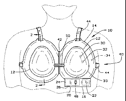
As shown in Figures 15 and 16, the "sticky" sole
78 need not necessarily underlie a rim cushion. As shown
in Figure 15, one of the intended embodiments of the
inventor's vacuum dome includes a bra 102 including a
30 pair of vacuum domes 104, 106 for increasing a woman's
breast size. The sticky sole which provides the seal for
the vacuum within vacuum domes 104, 106 may be applied
between the straps 108 which surround the domes 104, 106
and, in effect, separated from the rim cushions 46. With
35 this construction, the vacuum dome 104 and rim cushion 46
are mechanically separated from each other, although they
CA 02229992 1998-02-18
W O 97/067~6 PCTrUS96/13514
28
should be ~oined to ensure the seal between the vacuum
dome 104 and the underlying skin surface.
As shown in Figures 18 and 19, one embodiment of
the soft tissue enlargement apparatus 110 of the present
5 invention is generally comprised of a dome 112 having a
rim 114, a flexible sheet 116, and an intermediate
material 118 sandwiched between the dome and flexible
5 sheet. The material 118 may be any compliant material
which when cured shrinks to a smaller volume. Dep~n~ng
upon the material chosen, the curing may be accelerated
by ultraviolet light or other known means. The sheet 116
is adhesively bonded to the soft tissue underlying the
lO dome using double-sided tape, sheets or other detAc-hAhle
adhesive means 117. The adhesive means 117 may comprise
typical adhesives or glues, as well as, sticky gels or
sheets of double-sided adhesive tapes. Further, the
adhesive means 117 may be an adhesive substance embedded
15 in the sheet 116 or rim 114. As the material 118 shrinks
upon curing, the sheet 116 and therefore the soft tissue
which is bonded to it are drawn toward the rigid dome
112. In doing so, tensile stresses are developed in the
soft tissue which over time cause the tissue to enlarge.
20 The removable adhesive means 117 makes attachment more
convenient as the adhesive means may be removed from the
flexible sheet 116 when it has lost the ability to adhere
to the skin. A new adhesive means 117 may be applied to
the sheet 116 before the next application of the
25 apparatus 110 to assure that slippage does not occur.
Several forces are developed within the dome and
about the rim as a result of the stresses induced by the
shrinking material. A tensile force Ft is developed
within the material equal to the tensile stress Sl in the
30 soft tissue multiplied by the enclosed soft tissue
surface area A, 120. The vector sum of the tensile force
is referred to as the normal force F1 and is equal to the
tensile stress S1 developed in the soft tissue multiplied
CA 02229992 1998-02-18
W O 97/06756 PCTAUS96/13514
by the normal area Al 122 of the dome op~n;~g, i.e., Fl =
SlAl. The normal area Al is the projected area bounded by
the periphery 124. An opposing force F2 is imposed upon
the user by the rim 114 to balance the normal force Fl and
5 is equal to, but opposite, the normal force. This
opposing force F2 develops a compressive stress S2 in the
soft tissue underlying the rim 114. The compressive
stress S2 under the rim 114 is equal to the opposing force
F2 divided by the rim surface area A2 126, i.e., S2 = F2/A2
10 or F2 = S2A2. As the magnitude of the opposing force is
equal to the magnitude of the normal force, Fl = F2 and
SlAl = S2Az. Therefore, if the rim surface area A2 126 is
configured to be e~ual to the normal area Al 122 at the
dome opening, then the compressive stress in the
15 patient's underlying tissue will not exceed the magnitude
of the vacuum within the dome 112, i.e., S2 = Sl. Thus,
the rim surface area A2 124 may be sized with respect to
the normal area Al 122 so that the compressive stress S2
is maintained below 2666 N/m2 when the tensile stress S
20 within the soft tissue is maint~ine~ at less than 2666
N/m2. As studies have shown that no damage occurs to
typical soft tissue in hl ~n~ at tensile or compressive
stresses below 2666 N/m2, even when the stresses are
applied over an extended period of time, this limit
25 should not be ~x~-~e~ when relatively long periods of
use at constant stresses are desired. However, if the
tensile stress is cycled, different area ratios may be
used to optimize the therapeutic effects while l; n; m; zing
the potential for damage to the soft tissue within the
30 dome or beneath the rim.
In the specific embodiment shown in Figures 18 and
19, the rim 114 has a sur~ace area 128 equal to the
normal area 132 of the dome opening thereby preventing
medical complications to the soft tissue beneath the rim
35 as long as the tensile stress is properly regulated
within the dome 112. However, alternate ~hC)A; ?nts
CA 02229992 1998-02-18
W O 97/06756 PCT~US96/13514
within the dome 112. However, alternate embodiments
having a rim 114 with a surface area 126 equal to or less
than the normal area 122 of the dome opening may be used
~F~nAing upon the amplitude of the tensile stress used
5 and A~p~nAing upon whether the tensile stress is constant
or varied.
As shown in Figure 18, one specific embodiment may
take the form of a bra 130 having two domes 112 spaced by
a hinge 132. Straps 134 may be attA~h~A to the bra 130
10 to retain the bra 130 in place. A gasket 136 may also be
included about the rim 114 to improve the patient's
comfort and reduce shear stresses in the soft tissue as
will be explained in greater detail below. In the
preferred emboAi~ent~ this gasket 136 may be a silicone
15 gel cushion or other soft, conforming material having a
sufficient thickness to permit the skin under the rim to
shift laterally when excessive shear forces are imposed.
In another general embodiment, the tensile stress
S1 may be applied using elastic filaments or springs
20 instead of the intermediate material to develop the
tensile stress in the soft tissue. One such alternate
emboAi~ent is shown schematically in Figure 22. In this
embodiment, a flexible sheet of material 116 may be
adhesively bonded to the soft tissue which is desired to
25 be enlarged. A plurality of elastic filaments 140a-i may
be ~o~n~cted at spaced intervals to the sheet of material
116. These filaments 140a-i may also be conn~-ted to the
inner surface of the dome 112 so that they are held in
tension and the desired tensile force Ft is applied to the
30 sheet and thus the desired tensile stress S1 is induced in
the soft tissue enclosed by the dome. Dep~nAing upon the
filament spacing and the pre-set tension, the tensile
force Ft may be varied from place to place within the dome
112.
A variant embodiment using the same principal is
shown in Figure 23. In this variant embodiment, the
CA 02229992 1998-02-18
W O 97/06756 PCTrUS96/13514
soft tissue with an adhesive. However, in place of the
filaments 140a-i, non-extensible filaments 150a-h made of
a suitable material may be attached to the sheet of
material 116 and may be positioned to extend through a
5 plurality of holes 152a-h in the dome 112. These
filaments 150a-h may be joined or individually tensioned
using springs, weights, or any other known means to
subject the soft tissue to the tensile stress Ft. As with
the alternate embodiment shown in Figure 22, the variant
10 embo~i nt shown in Figure 23 may have a tensile force Ft
which varies from place to place by varying the spacing
and tensioning of the filaments 150a-h.
Imposing a constant tensile force Fe in the
filaments such as by using a weight att~ch~ to the
15 embo~i -nt shown in Figure 23 has an advantage over using
a tensioning means which relaxes as the soft tissue
enlarges. If the tissue only slightly protrudes into the
dome as shown in Figure 20 and as is typically the
initial condition, then the surface area 120 under the
20 dome is only slightly larger than the normal area 122 at
the dome opening. Therefore, the tensile stress S1 acts
on a surface area 120 which approaches the I ini~~l value
of the normal area. As enlargement occurs, more tissue
protrudes into the dome 112 as shown in Figure 21 thereby
25 providing more surface area 120 under the dome. Because
the surface area 120 under the dome is larger, the area
over which the tensile stress acts is larger. For a
given stress level, the enlargement of the soft tissue is
a function of the surface area. Therefore, the total
30 rate of enlargement of the soft tissue increases as
treatment continues because the surface area under the
dome is ever increasing. This however has no effect on
the opposing force, or for that matter the normal force,
as the tensile force Ft is a vector which must always sum
35 into the normal force. In other words, a unit of surface
area enlarges at a constant rate for any given stress,
CA 02229992 1998-02-18
W O 97/067S6 PCTrUS96/13514
but as the soft tissue surface area under the dome
increases, there are more units of surface area
increasing at the constant rate. Therefore, the total
rate of enlalg~ nt increases as treatment continues even
5 though the tensile stress is not increased.
Still another alternate embodiment is shown in
Figure 24. In this embodiment, the soft tissue may be
directly ho~e~ to a collapsible dome 160. The dome is
comprised of a plurality of ~-o~c~ntric annular bands
10 162a-j, an end plate 164, and an annular rim flange 166.
By collapsing and/or exten~ing the collapsible dome,
stress may be induced or relieved in the soft tissue.
Alternately, this alternate embodiment shown in Figure 24
may be used with a flexible sheet 116 and a compliant
15 intermediate material or spaced filaments as explained
above. Various locking means may be used with this
embodiment to hold the dome 160 in differing states of
extension to induce differing states of stress in the
soft tissue. Likewise, the annular bands 162a-j may be
20 formed with helical interlocking interfaces so that the
dome is expandable by rotation rather than axial
displAc~ ?~t.
Yet another alternate embodiment is shown in
Figure 25 which employs a variable volume dome or frame
25 170 rather than a rigid dome 112. The frame 170 is
comprised of a rim flange 172 similar to that of the
previously described embodiment. Attached to the rim
flange 172 are arcuate bands 174a-f which extend upward
and inward toward a pinion 176 located generally along
30 the centerline of the rim flange. Each of the arcuate
bands 174a-f includes a rack 178a-f which engages the
pinion 176. By rotating the pinion 176, the bands 174a-f
are forced either outward or inward to change the
enclosed volume of the frame 170. Because the frame is
35 attA~h~ to the soft tissue, this change in volume
induces a change in stress within the soft tissue. As
CA 02229992 1998-02-18
W O 97/06756 PCTAUS96/13514
with the previously described embodiment, this frame may
be directly applied to the soft tissue or att~che~ to a
sheet 116 which is adhesively hon~ to the soft tissue.
By turning the pinion, the tensile stress in the soft
5 tissue may be ad;usted. Variations of this embodiment
may have more or fewer than the six arcuate bands 172a-f
shown. Figure 26 shows a variation of the Figure 25
~ho~ nt where an iris ms-h~nism 180 made from leaves
182a-f is substituted for the arcuate band with rack and
10 pinion system shown in Figure 25. Figure 27 shows a
variation of the Figure 26 embodiment where a frame 190
made from a plurality of arcuate bands 192a-c are
att~ch~ to two concentric annular rim flanges 194a,b.
Rotation of the rim flanges 194a,b displaces the ends of
15 the arcuate bands 192a-c and thereby flexes the bands out
of plane to enlarge or reduce the volume enclosed by the
resulting frame 190. As with the embodiment of Figure
25, the embodiments of Figures 26 and 27 may also have
fewer or more leaves and bands.
In each of the above-described embodiments, the
gasket 136 attached to the rim 114 may be configured to
distribute any shear forces generated between the skin
and rim as the tensile force is applied. This shear
force distribution may be ~complished with the use of a
25 silicone gel or inflated membrane or bladder which has a
thickness sufficient to allow its surface 200 adjacent
the soft tissue to shift laterally with respect to the
rim. In this way, the shearing force is distributed
along the surface 200 adjacent the soft tissue so that
30 the force is not concentrated at the edge 202 of the rim
ad;acent the dome. In addition to distributing the shear
forces over a larger area, the gel or other flexible rim
material provides a cushion to improve the user's comfort
and inhibit contusions should an unintentional impact be
35 applied to the dome.
CA 02229992 1998-02-18
W O 97/06756 PCTAUS96/13514
34
In order to use the invention, the patient places
the dome over the area of desired enlaly~ -nt and adjusts
the straps for comfort. Then the patient simply actuates
the tensile force generating means and the device goes to
5 work. These apparatuses are in~n~e~ to be worn 8-12
hours per day and can be worn during sleep. A$ter
several months, notable and long-term enlargement should
occur. When the desired enla~yelllent is achieved, the use
of the device may be 8usp~n~1. If additional
10 enlargement is desired, then use may be cont;n~le~.
Occasional use or use at a reduced pressure may also be
desired to maintain the desired enlargement.
There are various changes and modifications which
may be made to the invention as would be apparent to
15 those skilled in the art. However, these changes or
modifications are included in the t~hi ng of the
disclosure and it is int~n~ that the invention be
limited only by the scope of the claims appended hereto.