Language selection

Search

Patent 2230035 Summary

Third-party information liability

Some of the information on this Web page has been provided by external sources. The Government of Canada is not responsible for the accuracy, reliability or currency of the information supplied by external sources. Users wishing to rely upon this information should consult directly with the source of the information. Content provided by external sources is not subject to official languages, privacy and accessibility requirements.

Claims and Abstract availability

Any discrepancies in the text and image of the Claims and Abstract are due to differing posting times. Text of the Claims and Abstract are posted:

  • At the time the application is open to public inspection;
  • At the time of issue of the patent (grant).
(12) Patent Application: (11) CA 2230035
(54) English Title: OILSANDS TAILINGS HEAT EXCHANGER
(54) French Title: ECHANGEUR DE CHALEUR POUR LES REJETS PROVENANT DU TRAITEMENT DES SABLES BITUMINEUX
Status: Deemed Abandoned and Beyond the Period of Reinstatement - Pending Response to Notice of Disregarded Communication
Bibliographic Data
(51) International Patent Classification (IPC):
  • F28D 7/10 (2006.01)
  • C10G 1/00 (2006.01)
  • F28F 1/40 (2006.01)
  • F28F 19/02 (2006.01)
(72) Inventors :
  • LANE, STEPHEN J. (Canada)
(73) Owners :
  • STEPHEN J. LANE
(71) Applicants :
  • STEPHEN J. LANE (Canada)
(74) Agent: THOMPSON LAMBERT LLP
(74) Associate agent:
(45) Issued:
(22) Filed Date: 1998-02-20
(41) Open to Public Inspection: 1998-03-20
Examination requested: 1998-02-20
Availability of licence: N/A
Dedicated to the Public: N/A
(25) Language of filing: English

Patent Cooperation Treaty (PCT): No

(30) Application Priority Data: None

Abstracts

English Abstract


An energy recovery system for an oilsands plant.
A heat exchanger is connected to a source of hot coarse
tailings from the oilsands plant. The heat exchanger is
provided by an inner pipe, surrounded by an outer pipe,
which together form an annulus, with fins extending from
the outer pipe into the annulus. The inner pipe has an
unobstructed interior bore. The outer pipe is preferably
spaced from the inner pipe by the fins. Cold water is
flowed into the annulus from an inlet to a hot water
outlet, preferably at opposed ends of the heat exchanger,
with flow in the annulus countercurrent to flow in the
inner pipe. The interior surface of the inner pipe is
preferably coated with abrasion resistant material,
preferably chromium carbide. The outer pipe is covered by
insulation.


French Abstract

Système de récupération de l'énergie utilisée dans une installation de traitement des sables bitumineux. Un échangeur de chaleur est formé d'un tuyau intérieur qu'entoure un tuyau extérieur. Ensemble, les deux tuyaux forment un espace annulaire, et des ailettes vont du tuyau extérieur vers l'espace annulaire. L'alésage du tuyau intérieur n'est pas obstrué. Le tuyau extérieur est, de préférence, éloigné du tuyau intérieur par les ailettes. De l'eau froide est introduite dans l'espace annulaire à partir d'une entrée jusqu'à une sortie d'eau chaude, de préférence, aux extrémités opposées de l'échangeur de chaleur, et l'écoulement à contre-courant dans l'espace annulaire passe dans le tuyau intérieur. La surface intérieure du tuyau intérieur est, de préférence, revêtue d'un matériau résistant à l'abrasion, notamment du carbure de chrome. Le tuyau extérieur est recouvert de matériau isolant.

Claims

Note: Claims are shown in the official language in which they were submitted.

THE EMBODIMENTS OF THE INVENTION IN WHICH AN EXCLUSIVE
PROPERTY OR PRIVILEGE IS CLAIMED ARE DEFINED AS FOLLOWS:
1. An energy recovery system for an oilsands plant,
comprising:
a source of hot coarse tailings from the oilsands
plant;
a inner pipe having an unobstructed interior bore
connected at an inlet end for receiving hot coarse tailings
from the source of hot coarse tailings, the inner pipe
having a discharge end;
an outer pipe disposed about the inner pipe, and
spaced from the inner pipe to form an annulus between the
inner pipe and outer pipe through which fluid may flow;
a heat transfer fluid inlet connected into the
annulus; and
a heat transfer fluid outlet connected into the
annulus and spaced from the heat transfer fluid inlet.
2. The energy recovery system of claim 1 further
comprising fins extending from the inner pipe into the
annulus.
3. The energy recovery system of claim 1 in which
the outer pipe is spaced from the inner pipe by plural fins
extending from the inner pipe into the annulus.

4. The energy recovery system of any of claims 1-3
in which the fins extend along the annulus from the inlet
end to the discharge end.
5. The energy recovery system of any of claims 1-4
in which the heat transfer fluid inlet is located between
the heat transfer fluid outlet and the discharge end.
6. The energy recovery system of any of claims 1-5
in which the heat transfer fluid inlet is located at the
discharge end of the inner pipe.
7. The energy recovery system of any of claims 1-6
in which the heat transfer fluid outlet is located at the
inlet end of the inner pipe.
8. The energy recovery system of any of claims 1-7
in which the interior of the inner pipe is coated with
abrasion resistant material.
9. The energy recovery system of any of claims 1-8
in which the interior of the inner pipe is coated with
chromium carbide.
10. The energy recovery system of any of claims 1-9
further comprising an insulating jacket disposed around the
exterior of the outer pipe.

11. The energy recovery system of any of claims 1-10
in which the inner pipe is straight.

Description

Note: Descriptions are shown in the official language in which they were submitted.


CA 0223003~ 1998-02-20
TIT~E OF THE lNV~NllON
Oilsands Tailings Heat Exchanger
NAME(S) OF lNV~NlOR(S)
Stephen J. Lane
FIELD OF THE lNv~NlION
This invention relates to the recovery of heat
from processes used in the separation of bitumen from
oilsands.
BACKGROUND OF THE lNv~NlION
Multiple phase mixtures of bitumen, water, sand,
fines and gases (~oilsands") form mineable and valuable
deposits in Alberta, ~n~A. To exploit such deposits, the
bitumen (or ~oil") must be removed from the oilsands.
Various methods are known to accomplish this removal such
as those described in United States patent no. 5,480,566 of
Strand issued January 2, 1996, and C~n~ n patent
application no. 2,165,252 of Re~ll and Lane published
June 16, 1996. The inventor has also proposed an improved
process for the removal of oil from oilsands in Canadian
application no. 2,205,208 filed June 13, 1997.
SUMMARY OF THE lNV~NlION
Common to all of these oil recovery systems is a
degree of heat loss. For example, for a plant operating at
300,000 B/d on an average grade of oil sands, about 50,000

CA 0223003~ 1998-02-20
tons per hour of waste slurry are produced at a temperature
of 180~F, with a heat loss from tailings at a rate of about
15 billion Btu/Hr.
This invention exploits the recognition, made by
the inventor, that recovery of heat loss from coarse
tailings may be made economically.
There is therefore provided in accordance with an
aspect of the invention, an energy recovery system for an
oilsands plant. A heat exchanger is connected to a source
of hot coarse tailings from the oilsands plant. The heat
exchanger is provided by an inner pipe, surrounded by an
outer pipe, which together form an annulus, with fins
extending from the outer pipe into the annulus. The inner
pipe has an unobstructed interior bore. The outer pipe is
preferably spaced from the inner pipe by the fins. Heat
transfer fluid, preferably cold water, is flowed into the
annulus from an inlet to a heat transfer fluid outlet,
preferably at opposed ends of the heat exchanger, with flow
in the annulus countercurrent to flow in the inner pipe.
The interior surface of the inner pipe is preferably coated
with abrasion resistant material, preferably chromium
carbide. The outer pipe is covered by insulation.
These and other aspects of the invention are
described in the detailed description of the invention and
claimed in the claims that follow.
BRIEF DESCRIPTION OF THE DRAWINGS
There will now be described preferred embodiments
of the invention, with reference to the drawings, by way of

CA 0223003~ 1998-02-20
illustration only and not with the intention of limiting
the scope of the invention, in which like numerals denote
like elements and in which:
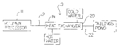
Fig. 1 is a schematic of a system according to
the invention;
Fig. 2 shows a side view of a tailing heat
exchanger according to the invention; and
Fig. 3 is a cross-section through the tailings
heat exchanger of Fig. 2 along the line 3-3.
DETAILED DESCRIPTION OF PREFERRED EMBODIMENTS
Referring to Figs. 1-3, there is shown an energy
recovery system incorporating a heat exchanger 10 for
removal of extra heat from coarse tailings output from an
oilsands plant. In this patent document, "coarse tailings"
are any tailings in which coarse tailigns may be present
and may include fine tailings (ie, may constitute whole
tailings). Hot water bitumen processor 11, which may be of
any designs known in the art, for example as shown in the
aforementioned patent and patent applications, acts as a
source of hot coarse tailings from the oilsands plant which
are provided along a conduit 12 into an inlet end 14 of a
pipe 16 having an unobstructed interior bore 18. Coarse
tailings flow along the pipe 16 to discharge end 20 where
cold tailings exit through outlet 22. The joint between the
conduit 12 and the inlet end 14 of the heat e~changer may
become a wear point, and obstruct the flow and/or leak.
Flanged connections may be bolted together with a high
temperature gasket on the inner pipe 24.

CA 0223003~ 1998-02-20
As shown in Fig. 3, an outer pipe 24 is
concentrically disposed about the inner pipe 16, and is
spaced from the inner pipe 16 to form an annulus 26 between
the inner pipe 16 and outer pipe 24. The outer pipe 24 is
spaced from the inner pipe 16 by plural fins 28 extending
along the annulus 26. It is preferred that the fins 28 are
discontinuous along the length of the heat exchanger 10 to
allow for mixing of fluid within the annulus, but the fins
28 may be continuous. The fins should be made of metal or
other material with high heat conduction such as mild steel
welded to the inner pipe. To prevent corrosion, inhibitors
may be added to water flowing through the annulus. The fins
28 may be made of ~x2 inch strip. Preferably from 4-12 fins
are used. Eight fins are a convenient number since it is an
easy number to fabricate spaced evenly about the inner pipe
24 at 45~ angles to each other. The fins 28 support the
inner pipe 16 in the outer pipe 24, but more importantly
the fins 28 conduct heat into the annulus 26 where it is
transferred to a flow of water (or other relatively inert
heat transfer fluid) flowing through the annulus 26.
The shape and volume of the annulus 26 is not
critical, although volume should be minimized and
concentricity is preferred due to manufacturing
requirements. The cross-sectional area of the annulus 26
may be about the same as or slightly larger than the cross-
sectional area of the inner pipe but may range from 0.1:1
to 10:1.
The device may be made by welding the fins 28
onto the inner pipe, and then sliding the outer pipe over

CA 0223003~ 1998-02-20
the fins. The outer pipe itself may be composed of an
annulus of concentric inner and outer pipes with insulation
in between.
To provide a flow of heat transfer fluid through
the annulus 26, a cold water inlet 30 is connected into the
annulus 26, preferably at the discharge end 20. A hot water
outlet 32 for the flow of water from the annulus 26 is
provided at the inlet end 14 of the heat exchanger 10. The
hot water outlet 32 must be spaced from the cold water
inlet 30 by an amount sufficient to provide a desired
degree of heat exchange. For a plant with 55,000 B/d
throughput, a 60 cm diameter inner pipe 24 may be used,
with the cold water inlet 30 separated from the hot water
outlet 32 by 30 m or more. Whatever the spacing between the
cold water inlet 30 and the hot water outlet 32, it is
preferred that the cold water inlet 30 is located between
the hot water outlet 32 and the discharge end 20. The water
supply may be through a high temperature synthetic such as
urethane.
The interior surface 34 of the inner pipe 16 is
coated with an abrasion resistant material, preferably
chromium carbide, according to known process for coating of
the inside of pipes with chromium carbide. The outer pipe
24 and chromium carbide liner be ~ inch or more thick, and
has a diameter depending on the application. An insulating
jacket 36, made of any suitable material such as glass
fiber or various foams, is disposed around the exterior of
the outer pipe 24.

CA 0223003~ 1998-02-20
The pipe 16 is preferably a straight 30 cm
diameter pipe. A bend in the pipe 16 will tend to form an
obstruction, and therefore the pipe should be straight.
With such a design, estimated heat exchange is predicted to
be 85% or more. Downstream of the heat exchanger 10,
t~il;ngs transfer through outlet 22 is preferably best
handled by flexible abrasion resistant HDPE (high density
polyethylene) plastic pipe, which also has sufficient
insulation capability to prevent freezing and clogging of
the output line 22. The hot water produced by the enerqy
recovery system of the present invention may for example be
recirculated for use in the bitumen processor, or used for
heating, or in other processes.
Depending on whether the slurry contains coarse
material, the slurry should be pumped at a rate sufficient
to maintain a slurry velocity of at least 8 meters per
second. The flow rate of water should be sufficient for the
water to nearly reach the input temperature of the slurry
by the time the water reaches the end 14 of the heat
exchanger. The inner diameter of the inner pipe is limited
by the size of solids in the slurry.
For a plant processing (a) 50,000 or (b) 300,000
tons per day of bitumen, and (a) one or (b) as many as
required 24 inch internal diameter inner pipes 24, (a)
10,000 tons or (b) 60,000 tons respectively of slurry can
be processed per hour in the heat exchanger. Multiple heat
exchangers, in parallel or serially arranged may be used.

CA 02230035 1998-02-20
Immaterial modifications to the invention
described may be made without departing from the essence of
the invention claimed.

Representative Drawing
A single figure which represents the drawing illustrating the invention.
Administrative Status

2024-08-01:As part of the Next Generation Patents (NGP) transition, the Canadian Patents Database (CPD) now contains a more detailed Event History, which replicates the Event Log of our new back-office solution.

Please note that "Inactive:" events refers to events no longer in use in our new back-office solution.

For a clearer understanding of the status of the application/patent presented on this page, the site Disclaimer , as well as the definitions for Patent , Event History , Maintenance Fee  and Payment History  should be consulted.

Event History

Description Date
Application Not Reinstated by Deadline 2001-02-20
Time Limit for Reversal Expired 2001-02-20
Deemed Abandoned - Failure to Respond to Maintenance Fee Notice 2000-02-22
Inactive: IPC assigned 1998-08-04
Inactive: First IPC assigned 1998-07-27
Inactive: IPC assigned 1998-07-27
Classification Modified 1998-07-27
Filing Requirements Determined Compliant 1998-05-11
Inactive: Filing certificate - RFE (English) 1998-05-11
Application Received - Regular National 1998-05-08
Application Published (Open to Public Inspection) 1998-03-20
Request for Examination Requirements Determined Compliant 1998-02-20
All Requirements for Examination Determined Compliant 1998-02-20

Abandonment History

Abandonment Date Reason Reinstatement Date
2000-02-22

Fee History

Fee Type Anniversary Year Due Date Paid Date
Application fee - small 1998-02-20
Request for examination - small 1998-02-20
Owners on Record

Note: Records showing the ownership history in alphabetical order.

Current Owners on Record
STEPHEN J. LANE
Past Owners on Record
None
Past Owners that do not appear in the "Owners on Record" listing will appear in other documentation within the application.
Documents

To view selected files, please enter reCAPTCHA code :


To view images, click a link in the Document Description column. To download the documents, select one or more checkboxes in the first column and then click the "Download Selected in PDF format (Zip Archive)" or the "Download Selected as Single PDF" button.

List of published and non-published patent-specific documents on the CPD .

If you have any difficulty accessing content, you can call the Client Service Centre at 1-866-997-1936 or send them an e-mail at CIPO Client Service Centre.


Document
Description 
Date
(yyyy-mm-dd) 
Number of pages   Size of Image (KB) 
Cover Page 1998-08-06 1 48
Abstract 1998-02-20 1 23
Description 1998-02-20 7 241
Claims 1998-02-20 3 61
Drawings 1998-02-20 2 16
Representative drawing 1998-08-06 1 4
Filing Certificate (English) 1998-05-11 1 163
Reminder of maintenance fee due 1999-10-21 1 111
Courtesy - Abandonment Letter (Maintenance Fee) 2000-03-21 1 183