Language selection

Search

Patent 2230537 Summary

Third-party information liability

Some of the information on this Web page has been provided by external sources. The Government of Canada is not responsible for the accuracy, reliability or currency of the information supplied by external sources. Users wishing to rely upon this information should consult directly with the source of the information. Content provided by external sources is not subject to official languages, privacy and accessibility requirements.

Claims and Abstract availability

Any discrepancies in the text and image of the Claims and Abstract are due to differing posting times. Text of the Claims and Abstract are posted:

  • At the time the application is open to public inspection;
  • At the time of issue of the patent (grant).
(12) Patent: (11) CA 2230537
(54) English Title: DECKING SYSTEM
(54) French Title: SYSTEME DE CONSTRUCTION DE TABLIER
Status: Expired and beyond the Period of Reversal
Bibliographic Data
(51) International Patent Classification (IPC):
  • E04F 15/10 (2006.01)
  • E01C 5/22 (2006.01)
  • E04B 5/12 (2006.01)
(72) Inventors :
  • HITE, JOHN D. (United States of America)
(73) Owners :
  • JOHN D. HITE
(71) Applicants :
  • JOHN D. HITE (United States of America)
(74) Agent: KIRBY EADES GALE BAKER
(74) Associate agent:
(45) Issued: 2002-05-21
(22) Filed Date: 1998-02-26
(41) Open to Public Inspection: 1999-03-15
Examination requested: 1998-02-26
Availability of licence: N/A
Dedicated to the Public: N/A
(25) Language of filing: English

Patent Cooperation Treaty (PCT): No

(30) Application Priority Data:
Application No. Country/Territory Date
08/929,115 (United States of America) 1997-09-15

Abstracts

English Abstract


A decking system utilizing non-skid plastic covers applied to specially
sawn wooden deck members is disclosed. The wooden deck members include a
plurality of channels or "kerfs" which are sawn or notched into one side of each
deck member. The covers have leg members which are specifically designed to
match or mate with the kerfs of the deck members. The kerfs of the deck
members and the leg members of the plastic covers have dimensions which allow
for the expansion and contraction of the deck members, as well as the
cross-sectional expansion and contraction of the covers, during periods of extreme
atmospheric conditions.


French Abstract

La présente invention a pour objet un système de construction de tablier utilisant des éléments de revêtement en plastique antidérapant posés sur des éléments d'ossature en bois sur lesquels des traits de scie ont été préalablement pratiqués. Chaque élément de l'ossature en bois du tablier comporte, sur une de ses faces, une série de traits de scie préalablement effectués. Les éléments de revêtement en plastique comportent des pattes qui sont spécialement conçues pour correspondre à l'emplacement des traits de scie effectués sur les éléments de l'ossature. Les dimensions des traits de scie, des pattes et des éléments de revêtement en plastique laissent place aux mouvements de dilatation et de contraction des éléments de l'ossature, de même qu'à la dilatation et à la contraction transversales des éléments de revêtement survenant durant les périodes de conditions atmosphériques extrêmes.

Claims

Note: Claims are shown in the official language in which they were submitted.

CLAIMS
1. A decking system comprising:
a plurality wooden deck members spacably attached to conventional
framing so as to form a floor or platform with each deck member having a
plurality of kerfs on a top side of said member; and,
a cap means attached to each deck member wherein said cap is
attached to the top side of said deck member containing said kerfs, said cap
means comprising:
an elongated sheath having a plurality of leg members spacably
positioned on the underside of said sheath so that said leg members
are dimensionally compatible with, and mate with, the kerfs of said
wooden deck member, wherein one or more of said leg members is
adhered to one or more of said kerfs via an adhesive.
2. The apparatus of Claim 1, wherein said cap means is embossed so as to
create a non-skid surface.
3. The apparatus of Claim 1, wherein said cap means is constructed of plastic
material.
4. The apparatus of Claim 1, wherein said kerfs comprise longitudinally
positioned, parallel, linear channels.
--9--

5. The apparatus of Claim 1, wherein one or more of said kerfs are angular
with
respect to other kerfs.
6. The apparatus of Claim 1, wherein one or more of said kerfs are non-linear.
7. The apparatus of Claim 1, wherein one or more of said kerfs are
curvilinear.
8. The apparatus of Claim 1, wherein two of said kerfs are positioned along
the
outer longitudinal edges of said deck member and extend the entire length
thereof.
9. The apparatus of Claim 1, wherein one or more of said leg members are
angular with respect to other leg members.
10. The apparatus of Claim 1, wherein one or more of said leg members are non-
linear.
11. The apparatus of Claim 1, wherein one or more of said leg members are
curvilinear.
12. The apparatus of Claim 1, wherein said deck members further comprise
wooden planks which have been treated with a wood preservative.
13. The apparatus of Claim 1, wherein said deck members have been pressure
treated with wood preserving chemicals.
14. A decking system produced by a process comprising the steps of:
creating, as by sawing or notching, a plurality of kerfs on a top side of
a plurality of wooden deck members;
placing adhesive into at least one of said kerfs;
--10--

attaching to said deck members an elongated sheath having a plurality
of leg members spacably positioned on the underside of said sheath so that
said leg members are dimensionally compatible with, and mate with, the
kerfs of said wooden deck member and at least one of said leg members is
adhered to one or more of said kerfs via the adhesive; and,
assembling said members onto framing so as to form a floor or
platform.
15. The product of Claim 14, wherein the process of producing said decking
system further comprises creating said kerfs as linear channels extending in
parallel
along the length of each deck member.
16. The product of Claim 14, wherein the process of producing said decking
system further comprises the creation of one or more of said kerfs as non-
linear
channels.
17. The product of Claim 14, wherein the process of producing said decking
system further comprises the creation of one or more of said kerfs as
curvilinear
channels.
18. The product of Claim 14, wherein the process of producing said decking
system further comprises the treatment of said deck members with a wood
preservative.
--11--

19. The product of Claim 14, wherein the process of producing said decking
system further comprises the pressurized treatment of said deck members with
wood preserving chemicals.
--12--

Description

Note: Descriptions are shown in the official language in which they were submitted.


CA 02230~37 1998-02-26
DECKING SYSTE~
by John D. Hite, Inventor
BACKGROUND OF THE INVEN'rION
This invention relates generally to decking materials and more
specifically to a uniquely designed deck system which incorporates specially sawn
wooden deck planks which are mated with companion, non-skid, plastic covers.
Wooden decks are utilized extensively in the construction industry
5 from residential patio decks to commercial decking for restaurants, apartments,
retail stores, marinas and other commercial establishments. Wooden decking is
also used for many other commercial and industrial applications such as platforms,
walkways, docks and piers. Moreover, structural wood framing and decking are
a cost effective means for expanding usable space while seasonably providing an
10 outdoor atmosphere for patrons, workers, guests and residents.
However, wood decking with all its advantages, when used in
applications which are exposed to outdoor atmospheric conditions will, over time,
tend to splinter, check, warp and rot as a result of the absorption of moisture and
the effects of alternating wettin~ and drying, free~ing and thawing and the
15 associated swelling and shrinking attributable to such exposures.

CA 02230~37 1998-02-26
It is known that wood will shrillk and swell very slightly along its
length, but will shrink and swell significantly in the direction of its annual growth
rings (tangentially) and about one-half as much "across" the rings (radially) (see
Figs. 4 & 5). These dimensional fluctuations should be taken into consideration
5 and accommodations made for same when designing a decking system utilizing
wooden planks.
Attempts have been made to overcome some of the problems
associated with wood decking by the use of plastic, steel and aluminum deck
members. However, all of these materials have cost disadvantages relative to
10 wood decking and have other disadvantages such as high corrosion, heat absorption
and transfer problems, high coefficient of expansion and low coefficient of friction.
It would be expedient, therefore, to provide a decking system which
utilizes the structural cost advantage of wood decking and, as a result of well
developed techniques, the ease of installation of wood decking, while at the same
15 time accommodating the physical characteristics of wood and eliminating other
problems and disadvantages associated with wood.
SUl\IMARY OF THE INVENTION
In view of the foregoing, it is a primary object of this invention to
20 provide a decking system and method which incorporates all the advantages of

CA 02230~37 1998-02-26
wood decking while virtually eliminating the disadvantages of long term use of
such material. According to an embodiment of the invention, a wood deck-cap
system utilizes specially sawn wooden planks which have been pressure treated
with a wood preservative for protection against decay associated with exposure to
5 moisture and heat. The planks are capped on one side with an embossed plastic
cover which provides for a non-skid surface. The covers are specifically designed
to mate with and attach to said specially sawn planks and have been extruded with
dimensions which allow for the expansion and contraction of the planks as well as
the cross-sectional expansion and contraction of the covers themselves. The covers
10 are adhered to the planks in a manner which restrains the cumulative longitudinal
expansion and contraction of the covers when exposed to ambient atmospheric
conditions.
More specifically, a preferred embodiment of the invention comprises
wooden planks having a plurality of grooves or kerfs sawn longitudinally into one
15 side of each plank. Attached to each plank is an embossed plastic or vinyl top
having spaced ribs specifically designed to match, and mate ~ith, the kerfs sa-vn
into the deck planks.
An advantage of the present invention is the provision of a deck
system which utilizes a durable non-skid plastic deck cover applied to wooden deck
20 planks, said covers being designed to accommodate and allow for the dimensional

CA 02230~37 1998-02-26
fluctuations inherent to such planks.
Another advantage of the present invention is the provision of a
decking system which is safe and cost effective yet superior to conventional
decking systems in its construction, durability and versatility.
5A further advantage of the present invention is the ability to design
and build decks of virtually unlimited colors without the use of high maintenance
finishes such as paint or stain.
Another advantage of the present invention is the provision of a
wooden deck-cap system having components with cross-sectional dimensions which
l0allow for the natural expansion and contraction of the components without shape
distortion.
A further advantage of the invention is the superior deterioration
protection and decay resistance afforded by the invention through the combination
of its pressure treated wooden planks and plastic deck caps.
Bl~IEF DESCRIPTION OF THE DRA~ 7G~
The foregoing and other objects, features, and advantages of the present
in~ention will be apparent from the following more particular description of
preferred embodiments as illustrated in the accompanying drawings in which
20reference characters refer to the same parts throughout the various views. The

CA 02230~37 1998-02-26
drawings are not necessarily to scale, emphasis instead being placed upon
illustratirlg the principles of the invention.
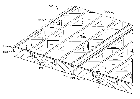
Fig. 1 is a perspective view of an embodiment of the decking system
of the present invention shown in an installed configuration.
Fig. 2 is an exploded, cross-sectional view of the components of the
embodiment of Fig. 1.
Fig. 3 is a cross-sectional view of the invention showing the
components of the invention in an installed configuration.
Fig. 4 is a cross-sectional view of a typical deck plank showing the
growth rings of the plank and identifying the tangential and radial
dimensions of the plank.
Fig. 5 is a cross-sectional view of a typical unmilled log showing the
characteristic shrirLka;,e and distortion of Yarious cuts of lumber as affected
by the direction of the annual growth rings.
DETAILED DESC~I~TION OF THE DRA~lNGS
In accordance with an embodiment of the invention, Fig. 1 shows a
decking system 100. The system 100 of Fig. 1 comprises a plurality of specially
~0 sawn wooden deck base members 400 with each member 400 having a cap means

CA 02230~37 1998-02-26
300 attached to, and covering one face side of, said wooden member 400. Said
cap means 300 extends substantially the length and width of said member 400 and
comprises a sheath means 310 having a plurality of ribs or leg members 301,302
which are spacably positioned on the underside of said sheath means 310. The
deck base members 400 are provided with a plurality of kerf means 200 sawn into
the face side of each member 400 for receiving the leg members 301,302 of said
sheath means 310.
In the present embodiment, said sheath means 310 is constructed of
pliable vinyl or plastic and, as best shown in the embodiment of Fig. 1, covers the
width and length of the face side of each deck member 400. The outer surface of
each sheath 310 is embossed so as to form a skid-resistant surface 303. Each
sheath 310 is provided with a pair of internal or "adhesion" legs 301 and a pair of
outer or "expansion" legs 302 for insertion into the matching kerfs 200 of the host
deck member 400. Said leg members 301,302 run the length of said sheath 310
and have dimensions ~I~hich allow the leg members 301,302 to be easily inserted
into the matching kerfs 200 of the host member 400. The dimensions and
positioning of the sheath legs 301,302 ~vithin said kerf means 200 allow for
expansion and contraction of the host deck member 400 during periods of extreme
atmospheric conditions.
The kerf means 200 of each deck base member 400 comprise one or

CA 02230~37 1998-02-26
more parallel "adhesion" kerfs 201 and a pair of "expansion" kerfs 202. The
adhesion kerfs 201 are sawn into each member 400 and form channels 210 which
run parallel to the length of the member 400 and are of sufficient width and depth
to receive the internal legs 301 of the sheath means 310. The expansion kerfs 202
s~wn are along the outer longitudinal edges of the deck face side of said member
400 and extend the length thereof. The expansion kerfs 202 are of sufficient width
and depth to receive the expansion legs 302 of the sheath means 310 and to also
provide additional space to allow the deck member 400 to expand radially and
tangentially to its potential without distorting the shape of the cap means 300. The
kerf means 200 and leg members 301,302 of the present embodiment are shown
having matching linear dimensions with respect to said deck membersA00 and with
respect to each other, however, matching non-linear, angular or curvilinear
dimensions are anticipated by the present invention as alternate embodiments.
During typical assembly, the deck base members 400 are fastened to
conventional structural wood framing using well established techniques and
conventional fasteners. The channels 210 of the adhesion kerfs 201 of said
members 400 are then filled with a commercial grade adhesive. Deck sheaths 310
of specified color, duty and dimensions are then positioned onto the deck base
members 400 with the adhesion legs 301 and the expansion legs 302 of said sheath
310 being positioned into their respective matching kerfs 201,202.

CA 02230537 1998-02-26
While the invention has been particularly shown and described with
reference to the preferred embodiments thereof, it will be understood by those
skilled in the art that various alterations in form and detail may be made therein
without departing from the spirit and scope on the invention.

Representative Drawing
A single figure which represents the drawing illustrating the invention.
Administrative Status

2024-08-01:As part of the Next Generation Patents (NGP) transition, the Canadian Patents Database (CPD) now contains a more detailed Event History, which replicates the Event Log of our new back-office solution.

Please note that "Inactive:" events refers to events no longer in use in our new back-office solution.

For a clearer understanding of the status of the application/patent presented on this page, the site Disclaimer , as well as the definitions for Patent , Event History , Maintenance Fee  and Payment History  should be consulted.

Event History

Description Date
Inactive: IPC from MCD 2006-03-12
Time Limit for Reversal Expired 2004-02-26
Letter Sent 2003-02-26
Grant by Issuance 2002-05-21
Inactive: Cover page published 2002-05-20
Inactive: Final fee received 2002-03-11
Pre-grant 2002-03-11
Inactive: Entity size changed 2002-02-20
Notice of Allowance is Issued 2001-09-12
Letter Sent 2001-09-12
Notice of Allowance is Issued 2001-09-12
Inactive: Approved for allowance (AFA) 2001-09-04
Amendment Received - Voluntary Amendment 2001-08-02
Inactive: S.30(2) Rules - Examiner requisition 2001-02-02
Application Published (Open to Public Inspection) 1999-03-15
Inactive: IPC assigned 1998-06-08
Classification Modified 1998-06-08
Inactive: IPC assigned 1998-06-08
Inactive: First IPC assigned 1998-06-08
Inactive: Filing certificate - RFE (English) 1998-05-14
Filing Requirements Determined Compliant 1998-05-14
Application Received - Regular National 1998-05-13
Request for Examination Requirements Determined Compliant 1998-02-26
All Requirements for Examination Determined Compliant 1998-02-26

Abandonment History

There is no abandonment history.

Maintenance Fee

The last payment was received on 2002-02-05

Note : If the full payment has not been received on or before the date indicated, a further fee may be required which may be one of the following

  • the reinstatement fee;
  • the late payment fee; or
  • additional fee to reverse deemed expiry.

Please refer to the CIPO Patent Fees web page to see all current fee amounts.

Fee History

Fee Type Anniversary Year Due Date Paid Date
Application fee - small 1998-02-26
Request for examination - small 1998-02-26
MF (application, 2nd anniv.) - small 02 2000-02-28 1999-11-24
MF (application, 3rd anniv.) - small 03 2001-02-26 2001-02-06
MF (application, 4th anniv.) - standard 04 2002-02-26 2002-02-05
Final fee - standard 2002-03-11
Owners on Record

Note: Records showing the ownership history in alphabetical order.

Current Owners on Record
JOHN D. HITE
Past Owners on Record
None
Past Owners that do not appear in the "Owners on Record" listing will appear in other documentation within the application.
Documents

To view selected files, please enter reCAPTCHA code :


To view images, click a link in the Document Description column. To download the documents, select one or more checkboxes in the first column and then click the "Download Selected in PDF format (Zip Archive)" or the "Download Selected as Single PDF" button.

List of published and non-published patent-specific documents on the CPD .

If you have any difficulty accessing content, you can call the Client Service Centre at 1-866-997-1936 or send them an e-mail at CIPO Client Service Centre.


Document
Description 
Date
(yyyy-mm-dd) 
Number of pages   Size of Image (KB) 
Abstract 1998-02-26 1 17
Description 1998-02-26 8 232
Claims 1998-02-26 4 88
Drawings 1998-02-26 2 86
Cover Page 1999-03-23 2 66
Representative drawing 2002-04-22 1 26
Claims 2001-08-02 4 95
Drawings 2001-08-02 2 90
Cover Page 2002-04-22 1 51
Representative drawing 1999-03-23 1 18
Filing Certificate (English) 1998-05-14 1 163
Reminder of maintenance fee due 1999-10-27 1 111
Commissioner's Notice - Application Found Allowable 2001-09-12 1 166
Maintenance Fee Notice 2003-03-26 1 174
Correspondence 2002-03-11 1 34