Note: Descriptions are shown in the official language in which they were submitted.
CA 02230669 1998-02-27
WO 97/09016 PCTIUS96/13729
ABSORBENT ARTICLE HAVING CONlPLIANT CUFFS
Field of the Invention
The present invention relates an absorbent article
for use in the perineal area of the body, such as
sanitary napkins, incontinence pads, and the like, and
more specifically relates to an absorbent article having
compliant side cuffs along the lateral edges of the
absorbent article that provide enhanced conformability
of the absorbent article to the wearer's body, thereby
inhibiting or preventing leakage past the lateral sides
of the absorbent article.
Backqround of the Invention
Traditional absorbent articles are generally
characterized as having a body fluid pervious material
defining a body facing side, a body fluid impervious
material defining a garment facing side, and a central
absorbent core between the body facing side and the
garment facing side. The body facing side layer and the
garment facing side layer are generally sealed around
the outer edge margins of the central absorbent core so
as to form laterally extending flanges (see, for example
U.S. Patent No. 4,678,527 to Ulman).
Under certain circumstances, absorbent articles are
subject to lateral leakage, for example, if the article
is locally not in contact with the perineum because of
wrinkling or deformation of the absorbent article or if
= the flow of body fluids exceeds the local absorbent
1
SUBSTITUTE SHEET (RULE 26)
CA 02230669 1998-02-27
WO 97/09016 PCTIUS96/13729
capacity of the absorbent article. Such lateral leakage
causes fluid to flow along and beyond the surface of the
perineum to the user's legs often resulting in soiling
of the undergarment or other clothing articles.
Attempts have been made to enhance the fit of such
absorbent products by imparting an arcuate shape to the
article in the longitudinal direction. This is
typically accomplished by applying longitudinally
extending elastic elements placed in tension to the
article (see, for example U.S. Patent Nos. 3,236,238 to
Morse and 4,432,823 to Moore).
U.S. Patent No. 4,701,177 to Ellis et al. discloses
a sanitary napkin in which the absorbent core in the
central portion of the napkin has a dog bone shape,
i.e., the width of the absorbent core is reduced in the
central portion. The cover layer and barrier layer are
sealed along their lateral edges in a contour which
follows the top edges of the lateral sides of the
central absorbent core. As a result, in the reduced
width central portion of the napkin, there are portions
of the cover and barrier which are outward of the
absorbent core which tend to form walls. Elastic
members disposed within the walls cause them to extend
upward above the body facing surface and into the crease
at the sides of the pudendum so as to prevent leakage.
However, this arrangement suffers from several
drawbacks.
First, as a result of the placement of the seal
lines at the top of the sides of the central portion,
the walls have a tendency to fold inward about the joint
lines in use so that they lay over the body facing 2
SUBSTiTUTE SHEET (RULE 26)
CA 02230669 1998-02-27
WO 97/09016 PCT/US96/13729
surface, thereby reducing the effective area of the
central absorbent portion. Second, the formation of
walls requires that the central portion be formed into a
dog bone shape so that this sealing approach is not
applicable to all types of napkins. Third, the
materials that form the walls are limited to those
suitable for napkin covers and barriers. Finally, since
the. perineal area of the body does not have an arcuate
or cup shape, these products are not fully effective for
maintaining contact between the perineal area and the
absorbent product.
Other attempts to prevent lateral side leakage in
absorbent articles have been to provide wings or flaps
which wrap around the crotch portion of the wearer's
undergarment to cover and thus protect the undergarment.
For example, U.S. Patent No. 4,285,343 to McNair or U.S.
Patent No. 4,589,876 to Van Tilburg disclose sanitary
napkins having wings in which flexible axes are formed
that allow the wings to be folded over the edges of the
panty crotch. In Van Tilburg, each wing is joined to the
central portion of the napkin along a preferential
bending line. The width of the central portion is less
than the span of the perineum so that the elastic in the
panty crotch bends the wings upward around the
preferential bending line. This bending action causes
the wings to form walls that bear against the laterally
outward surfaces of the perineum to produce a seal that
is described as being gasket-like. Unfortunately, such
articles suffer from several drawbacks.
First, since the article relies on the panty
elastic to bend the wings upward around the laterally
3
SUBSTiTUTE SHEET (RULE 26)
CA 02230669 1998-02-27
WO 97/09016 PCTIUS96/13729
outward surfaces of the perineum at the preferential
bending joints between the wings and the central
portion, the maximum width of the central portion is
limited to the width of the panty crotch. This limits 5 the absorbent capacity
of the napkin as well as its
applicability to a large variety of panty sizes.
Second, since the wings are folded over the edges
of the panty crotch, the seals formed thereby can extend
beyond the edges of the crotch only by the thickness of
the wings. As a result, optimal contact of the seal
with the body will not be attained for all users since
the seal does not extend a substantial distance beyond
the edge of the crotch. Again, this limits the
applicability of the napkin.
Third, although the preferential bending line and
flexible axis give the wing flexibility in the direction
normal to the plane of the wing, the wing is relatively
stiff in response to a compression force applied in the
plane of the wing. Hence, the compliancy of the wings
is low, resulting in discomfort due to the wings digging
into the body.
Fourth, since the elastic portion of the crotch is
disposed at the top of the wall formed by the wing, the
force imposed by deformatiori of the elastic portion acts
to press only the wing against the user's body. The
elastic portion does not push the central portion of the
article against the perineum so as to ensure proper
contact.
Absorbent articles in which the layers are joined
4
SUBSTITUTE SHEET (RULE 26)
1 CA 02230669 1998-02-27
PPC-587
by forming flanges, as discussed abo Je, st.ffEr from the
drawback that although the flanges are flexible with
respect to forces acting perpendicular to the plane of
the flange, they are fairly rigid in response to forces
acting in-plane. Consequently, the flanges of such
articles have a tendency to dig into the skin of the
user, causing discomfort.
U.S. Patent No. 4,695,278 to Lawson discloses a
diaper in which flaps are formed by extending the cover
and barrier beyond the sides of the central portion and
joining them together along longitudinally extending
joint lines spaced transversely from the central portion
sides. Elastic members are disposed within the flaps,
to form members characterized as "barrier cuffs."
Members characterized as barrier cuffs are formed by
attaching strips of material, folded over so as to form
loops at their distal ends, to the flaps along the joint
lines. Elastic members are disposed within the loops
causing them to extend vertically upward above the body
facing surface. Unfortunately, as a result of the
length of the barrier cuffs and the spacing of the joint
lines away from the sides of the central portion, the
barrier cuffs, like the walls in the Ellis patent, have
a tendency in use to fold inward about the joint lines
so that they lay over the body facing surface, thereby
reducing the effective area of the central absorbent
portion.
European Patent Application EP A 0 534 488
discloses an absorbent article having compliant gaskets
along the longitudinal sides of the article. WO
93/12747 discloses an absorbent article having
elasticized side flaps.
fc,
AMEPJDED SHEET
CA 02230669 1998-02-27
PPC-587
Consequently, it is desirable to provide an
absorbent article that overcomes the aforementioned
drawbacks associated with absorbent articles heretofore
known in the art. Such an article should be capable of
ic.
_/ .
sa. AMENDED SHEET
CA 02230669 1998-02-27
WO 97/09016 PCT/US96/13729
preventing lateral leakage of fluid; maintain body
contact with the effective area of the central absorbent; be adapted to fit
properly regardless of the
size of the user or the undergarment; be sufficiently 5 compliant to provide a
comfortable fit and have the
surface properties which minimize any unpleasant
sensation of such contact while ensuring a good fit and
proper contact of the central portion of the absorbent
article with the body.
Summary of the Invention
It is an object of the current invention to provide
an absorbent article which inhibits or prevents leakage
of fluid past the lateral edges of the absorbent
article.
It is another object of the current invention to
provide an absorbent article which is suitable for use
in undergarments having a large range of sizes.
It is yet another object to provide an absorbent
article having compliant side cuffs which make good
sealing contact with the user's body and yet are
comfortable.
In accordance with the present invention, these and
other objects have been provided in an absorbent article
for use in the perineal area of a user's body to absorb
body fluid, said absorbent article having right and left
lateral sides and first and second transverse ends, said
absorbent article comprising:
a) a fluid pervious first layer forming a body
6
SUBSTiTUTE SHEET (RULE 26)
CA 02230669 1998-02-27
WO 97/09016 PCTIUS96/13729
facing surface;
b) a fluid impervious second layer forming a
garment facing surface opposite the body facing
surface;
c) an absorbent core positioned between the first
layer and the second layer;
d) right and left longitudinally extending cuffs,
the cuffs having a base portion and a distal end,
each of the cuffs comprising a longitudinal strip
of a resilient, highloft, fluid permeable material
which is covered, at least in part, with a
flexible, fluid repellent porous material, and
wherein the right and left longitudinally extending
cuffs are attached along their respective base
portions to the right and left lateral sides of the
absorbent article, respectively, such that the
distal ends of the cuffs extend outward from the
right and left lateral sides of the absorbent
article.
Also provided in accordance with the present
invention is an absorbent article for absorbing fluid
in the perineal area of the user's body and adapted for
use in conjunction with an undergar-ment having a crotch
portion having right and left edges, the absorbent
article comprising:
a) a fluid pervious first layer forming a body
facing surface, a fluid impervious second layer
forming a garment facing surface opposite the body
facing surface, an absorbent core between the first
and second layers and having right and left
longitudinally extending opposing sides, the first
and second layers having first joining means for
7
SUBSTITUTE SHEET (RULE :26)
CA 02230669 1998-02-27
WO 97/09016 PCTIUS96/13729
joining the first and second layers, thereby
forming right and left flanges adjacent the right
and left sides of the absorbent core, respectively;
b) right and left longitudinally extending cuffs,
each cuff comprising a longitudinal strip of a
resilient, highioft, fluid permeable material which
is covered, at least in part, with a flexible,
fluid repellent porous material, each cuff having a
base portion and a distal end, wherein each cuff is
attached along its respective base portion to the
absorbent article adjacent the right and left
flanges and wherein the distal end of each cuff
extends outward therefrom, whereby the distal ends
of the cuffs are compressed against a portion of
the user's body in use;
c) right and left wings each having a base portion
and a distal end portion, the base portion being
attached to the fluid impervious layer inwardly
from the lateral edges of the absorbent article,
thereby forming right and left pockets, the distal
end portion adapted to fold over and retain the
right and left edges of the undergarment crotch
portion in the right and left pockets,
respectively.
Also provided in accordance with the present
invention is an absorbent article for use in the
perineal area of a user's body to absorb body fluid, the
absorbent article having right and left lateral sides
and first and second transverse ends, the absorbent
article comprising:
a) a fluid pervious first layer forming a body
facing surface;
8
SUBSTITUTE SHEET (RULE 26)
CA 02230669 1998-02-27
WO 97/09016 PCT/US96/13729
b) a fluid impervious second layer forming a
garment facing surface opposite the body facing
surface;
c) an absorbent core positioned between the first
layer and the second layer wherein the first layer
has right and left approximately longitudinally
extending edges, and the secor.id layer has right and
left approximately longitudinally extending edges,
and wherein the first layer is joined to the second
layer adjacent to their respective right and left
edges so as to form right and left flanges, wherein
the right and left flanges are adjacent the right
and left lateral sides of the absorbent article;
d) right and left longitudinally extending cuffs,
the cuffs having a base portion and a distal end,
each of the cuffs comprising a longitudinal strip
of a resilient, fluid permeable, highloft material,
and a longitudinal strip of an apertured polymeric
film which encloses the highloft material along at
least a substantial portion of its length and
wherein the right and left longitudinally extending
cuffs are adhered along their respective base
portions to the right and left lateral sides of the
absorbent article, respectively, such that the
distal ends of the cuffs extend outward from the
right and left flanges;
e) right and left wings each having a base portion
and a distal end portion, the right and left wings
attached at their respective base portions to the
right and left flanges, respectively, and forming a
part thereof, and the distal ends being foldable
over a crotch portion of a user's undergarment.
9
SUBSTITUTE SHEET (RULE 26)
CA 02230669 2007-05-23
In accordance with a first broad aspect, the invention
provides an absorbent article for use in a perineal area of
a user's body to absorb body fluid, the absorbent article
having right and left lateral sides and first and second
transverse ends, the absorbent article comprising:
a) a fluid pervious first layer forming a top body
facing surface;
b) a fluid impervious second layer forming a bottom
garment facing surface opposite the body facing
surface;
c) an absorbent core positioned between the first
layer and the second layer; and
d) right and left cuffs which extend along opposite
right and left lateral sides of the absorbent
article, the cuffs having a base portion and a
distal end, each of the cuffs comprising a strip of
a resilient, highloft, fluid permeable material
which is covered, at least in part, with a
flexible, fluid repellent porous material, and
wherein the right and left cuffs are attached along
their respective base portions to the right and
left lateral sides of the absorbent article,
respectively, such that the distal ends of the
cuffs extend outward from the right and left
lateral sides of the absorbent article.
In accordance with a second broad aspect, the invention
provides an absorbent article for absorbing fluid in the
perineal area of a user's body and adapted for use in
conjunction with an undergarment having a crotch portion
-9a-
CA 02230669 2007-05-23
having right and left edges, the absorbent article
comprising:
a) a fluid pervious first layer forming a body
facing surface, a fluid impervious second layer
forming a garment facing surface opposite the
body facing surface, an absorbent core between
the first and second layers and having right and
left longitudinally extending opposing sides, the
first and second layers having first joining
means for joining the first and second layers,
thereby forming right and left flanges adjacent
the right and left sides of the absorbent core,
respectively;
b) right and left longitudinally extending cuffs,
each cuff comprising a longitudinal strip of a
resilient, highloft fluid permeable material
which is covered, at least in part, with a
flexible, fluid repellant porous material, each
cuff having a base portion and a distal end,
wherein each cuff is attached along its
respective base portion to the absorbent article
adjacent the right and left flanges and wherein
the distal end of each cuff extends outward
therefrom, whereby the distal ends of the cuffs
are compressed against a portion of the user's
body in use; and
c) right and left wings each having a base portion
and a distal end portion, the base portion being
attached to the fluid impervious layer inwardly
from the lateral edges of the absorbent article,
thereby forming right and left pockets, the
-9b-
CA 02230669 2007-05-23
distal end portion adapted to fold over and
retain the right and left edges of the
undergarment crotch portion in the right and left
pockets, respectively.
In accordance with a third broad aspect, the invention
provides an absorbent article for use in the perineal area
of a user's body to absorb body fluid, the absorbent
article having right and left lateral sides and first and
second transverse ends, the absorbent article comprising:
a) a fluid pervious first layer forming a body
facing surface;
b) a fluid impervious second layer forming a garment
facing surface opposite the body facing surface;
c) an absorbent core positioned between the first
layer and the second layer wherein the first
layer has right and left approximately
longitudinally extending edges, and the second
layer has right and left approximately
longitudinally extending edges, and wherein the
first layer is joined to the second layer
adjacent to their respective right and left edges
so as to form right and left flanges, wherein the
right and left flanges are adjacent the right and
left lateral sides of the absorbent article;
d) right and left longitudinally extending cuffs,
the cuffs having a base portion and a distal end,
each of the cuffs comprising a longitudinal strip
of a resilient, fluid permeable, highloft
material, and a longitudinal strip of an
apertured polymeric film which encloses the
-9c-
CA 02230669 2007-05-23
highloft material along at least a substantial
portion of its length and wherein the right and
left longitudinally extending cuffs are adhered
along their respective base portions to the right
and left lateral sides of the absorbent article,
respectively, such that the distal ends of the
cuffs extend outward from the right and left
flanges; and
e) right and left wings each having a base portion
and a distal end portion, the right and left
wings attached at their respective base portions
to the right and left flanges, respectively, and
forming a part thereof, and the distal ends being
foldable over a crotch portion of the user's
undergarment.
-9d-
CA 02230669 1998-02-27
WO 97/09016 PCT/US96/13729
Brief Description of the Drawings
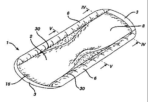
Figure 1 is an isometric view of one embodiment of
an absorbent article according to the current invention.
Figure 2 is a plan view of the article shown in
Figure 1.
Figure 3 is an elevation view of the article shown
in Figure 1.
Figure 4 is a transverse cross-section through the
article shown in Figure 1 taken through line IV-IV.
Figure 5 is a transverse cross-section through the
article shown in Figure 1 taken through line V-V.
Figures 6 and 7 are detailed views of embodiments
of the portion of the article shown in Figure 5 enclosed
by the circle VI.
Figure 8 is a transverse cross-section through the
embodiment of the article shown in Figure 1 in use.
Figure 9 is a transverse cross-section through a
another embodiment of the article shown in Figure 1.
Figure 10 is a transverse cross-section through a
still another embodiment of the article shown in Figure
1.
Figures 11 (a)-(d) are detailed views of
embodiments of the portion of the article shown in
SUBSTITUTE SHEET (RULE 26)
CA 02230669 1998-02-27
WO 97/09016 PCTIUS96/13729
Figure 10 enclosed by the circle X.
Figure 12 is a transverse cross-section through a
still another embodiment of the article shown in Figure
1.
Figures 13 (a)-(c) are detailed views of
embodiments of the portion of the article shown in
Figure 12 enclosed by the circle XIII.
Figure 14 is an isometric view of yet another
embodiment of an absorbent article according to the
current invention having wings.
Figure 15 is an elevation view of the article shown
in Figure 14.
Figure 16 is a transverse cross-section through the
article shown in Figure 14 taken through line XVI-XVI.
Figures 17 (a)-(c) are detailed views embodiments
of the portion of the article shown in Figure 16
enclosed by the circle XVII.
Figure 18 is a transverse cross-section through the
article shown in Figure 14 in use.
Figure 19 is a plane view from below of the
embodiment of the article shown in Figure 14 in use.
Figure 20 is a transverse cross-section through
another embodiment of the article shown in Figure 14 in
use.
11
SUBSTITUTE SHEET (RULE 26)
CA 02230669 1998-02-27
WO 97/09016 PCT/US96/13729
Figure 21 shows an alternate embodiment of the cuff
shown in Figure 6. Figure 22 shows two alternate embodiments of the
cuff shown in Figure 13.
Dnscription of the Preferred Embodiments
The present invention is directed to an absorbent
article for use in the perineal area of a user's body to
absorb body fluid. The absorbent article has right and
left lateral sides and first and second transverse ends
and comprises: a) a fluid pervious first layer forming
a body facing surface; b) a fluid impervious second
layer forming a second surface opposite the body facing
surface; c) an absorbent core positioned between the
first layer and the second layer; d) right and left
longitudinally extending compliant cuffs.
The cuffs comprise a longitudinal strip of high
loft material and a longitudinal strip of fluid
repellent porous material which encloses the high loft
material along at least a substantial portion of its
length. The compliant cuffs of the present invention
have a base portion and a distal end portion, and are
attached along a substantial portion of their respective
base portions to the right and left lateral sides of the
absorbent article, respectively, such that the distal
end portions of the cuffs extend outward from the right
and left lateral sides of the absorbent article.
The strip of high loft material 47 may be formed
from a fibrous woven or nonwoven flexible fabric that is
12
SUBSTiTUTE SHEET (RULE 26)
CA 02230669 2006-04-11
soft, comfortable, and cushiony,to provide a cotnfortab].e
"feel" to the user, and also possesses an open, fluid-
permeable structure, i.e., having void spaces which are
capable of holding or retaining fluid, and which may
S optionally be capable of drawing fluid away from the
fluid repellent porous material which covers the high
loft material to provide a'clean-dry' appearance to the
cuff. As used herein the term 'higr, loft material'
refers to materials which either as a single layer or as
a multi-layer laminate provide a total thickness of the
cuff of at least 0.635mm (25 mils) The exact thickness
of either the high loft material or the apertured
polymeric film is not per se critical to the invention,
provided of course, that the total thickness of the cuff
is at least 0.635mm (25 mils), preferably at least
1.02mm (40 mils), and most preferably between 1.02mm -
2.032mm(40 and 80 mils). The strip of high loft
material 48 may be wicking or non-wicking, and is
preferably non-wicking so as not to promote the flow of
fluid beyond the cuff 6. The resilient, fluid permeable
high loft material is preferably flexure resistant.
Flexure resistance is generally measured by peak bending
stiffness which is more fully discussed in U.S. patent
5,171,302 to Buell.
The high loft material of the present
invention preferably has a peak bending stiffness of at
least 100 grams, preferably greater than 200 grams, and
most preferably between 250 grams and 1000 grams.
Suitable resilient, fluid permeable high loft
materials include, but are not limited to, high loft
polyesters, polyethylene/polyester bi-component fibers,
wood pulp such as air laid pulps, wet laid pulps, and
the like, pulp-fiber blends, laminates of the above
- 13 -
CA 02230669 2006-04-11
materials or further laminated to polymeric films, with
the prc)-7iso that the upper-most layer in the laminate
structure, (which corresponds to the body-facing side of
the absorbent article) possesses an open, fluid
permeable structure capable of holding or retaining
fluid, and combinations of the above materials. A
particularly preferred material is a fusible fiber which
is commercially available under the trademark ENKAT"
having a bulk density of about 0.5 oz./sq. yd. and a
thickness of about 9 mils.
In addition to a comfortable feel, the cuffs
preferably provide a smooth, curved, edgeless surface at
their distal ends that serves as the contact surface for
the cuff against the body, as shown in Figure S. Such
contouring of the cuff contact surface minimizes any
discomfort associated with such contact under pressure.
Suitable materials for use as the fluid repellent
porous material include, but are not limited to, any of
the conventional fluid repellent materials used as fluid
pervious cover layers in commercially available
absorbent sanitary products as discussed for fully
below. A preferred material for use as the fluid
repellent porous material is an apertured polymeric
film. A particularly preferred apertured polymeric film
which may be used both as the cover layer and as the
fluid repellent porous material to cover the high loft
material of the cuff is disclosed in Canadian Patent
Application 2,130,176.
In a most preferred embodiment, the
apertured polymeric film is applied as a separate strip
of material which is attached to the side cuffs while
14
CA 02230669 1998-02-27
PPC-587
the film is slightly tensioned. Al~ernatlveiy, ic.is
also possible to use the same apertured polymeric film
which was used as the cover layer to simultaneously form
the side cuffs as shown in Figure 12 - 13.
The surface 16 of the absorbent article that is
intended to be worn against the body of the user (i.e
the body facing surface) is covered by a layer 8 of a
body-fluid pervious material, typically referred to as a
"cover layer". The cover layer 8 may be formed from any
fluid pervious material that is comfortable against the
skin and that permits fluid to penetrate to the
underlying core 7, which retains the fluid. The cover
layer 8 is preferably fluid repellent, i.e. it should
retain little or no fluid in its structure to provide a
relatively dry surface next to the skin. The fluid
pervious cover layer 8 may be a fibrous woven or
nonwoven fabric made of fibers or filaments of polymers
such as cotton, rayon, nylon, polyethylene,
polypropylene, polyester, bi-component fibers of
polyester sheathed in polyethylene or polypropylene,
bi-component fibers of polypropylene sheathed in
polyethylene, fibers of high melting polyester sheathed
in low melting polyester, and combinations thereof.
In a most preferred embodiment, the cover layer 8
may be formed from an apertured polyineric film. The
thickness of the cover layer 8 will vary from
approximately 0.254 to 1.57mm (0.00:L to 0.062 inch),
preferably from 0.127 to 0.57mm (0.005 to 0.020 inch)
and most preferably from 0.254 to 0.381mm (0.010 to
0.015 inch). Generally, the fluid pervious cover layer 8
is a single sheet of material having a surface area
sufficient to cover the body-facing surface 16 of the
- 15 -
a1MEN0ED SHEET
CA 02230669 1998-02-27
PPC-587
absorbent article. Preferably, the.fluid pErvioua cover
layer 8 is longer than the core 7 so as to form the
transverse ends 3. The transverse ends 3 may be sealed
with other pervious or non-pervious layers to fully
enclose the central absorbent core.
The absorbent article 1 further comprises a layer 9
of a body fluid impervious material, typically referred
to as a "barrier layer", on its garialent facing surface
17. The fluid impervious barrier layer 9 may comprise
any thin, flexible, body fluid impermeable material and
is typically a polymeric film such as, for example,
polyethylene, polypropylene, cellophane, and the like.
Alternatively, the barrier layer may be a normally fluid
pervious material that has been treated to be
impervious, such as impregnated fluid repellent paper,
woven or nonwoven fabric material, closed cell flexible
foams, such as polyurethane or cross-linked
polyethylene. The fluid impervious barrier layer may
optionally be permeable to gas including water vapor to
provide an air breathable fluid barrier. The thickness
of the barrier layer is not per se critical to the
invention, provided of course that it is flexible. A
typical barrier layer thickness, when formed from a
polymeric film, is in the range of from 0.0127 to 0.635
mm (0.0005 to 0.025 inch) and is preferably in the range
0.254 to 0.508mm ( 0.001 to 0.002 inch).
The barrier layer 9 generally comprises a single
sheet of material having a surface area sufficient to
cover the entire garment-facing surface 17 of the
absorbent article. As shown in Figures 4-9, the fluid
impervious barrier layer 9 may extend around the sides
of the core 7 in a C-shaped configuration with the
- 16 -
aMEhro~D SHEET
CA 02230669 1998-02-27
WO 97/09016 PCT/US96/13729
of the core 7 in a C-shaped configui-ation with the
portions 10 of the barrier layer that are adjacent its
longitudinal edges 32 extending upwardly from the
garment facing surface 17 toward the body facing surface
16 so as to form a portion of the lateral sides 30 of
the absorbent article 1.
The construction the absorbent article 1 is shown
in Figures 4 and 5. The central por=tion 2 of the
absorbent article contains an absorbent core 7. As is
known in the art, the absorbent core 7 may be comprised
of a loosely associated absorbent hydrophilic material
such as cellulose fibers, including wood pulp, wet or
dry cross-linked wood pulp, curly wood pulp fibers,
rayon fibers or cotton fibers, or other absorbent
materials generally known in the art, including acrylate
fibers, polyvinyl alcohol fibers, peat moss or super-
absorbent particles or fibers. The absorbent core may
also comprise synthetic fibers such as nylon,
polyethylene, polypropylene, polyester, bi-component
fibers of polyester sheathed in polyethylene or
polypropylene, bi-component fibers of polypropylene
sheathed in polyethylene, fibers of high melt polyester
sheathed in low melt polyester, and combinations
thereof. These fibers may be layered to form an
absorbent core having a porosity gradient, and/or may be
treated with a surfactant to make them hydrophilic and
thereby wettable.
In a preferred embodiment, the central portion of
the absorbent core has an hour glass shape and is
thicker (i.e. in the "z" direction) in its center region
thari at its end portions, thus creating an absorbent
17
SUBSTITUTE SHEET (RULE 26)
CA 02230669 2006-04-11
article having a raised center portion, as ~tiiowa in
Figures 1 - 5. The relative thickness of the center
region is not, per se, critical to the invention, and is
generally from 1.1 to 4 times thicker than the
transverse end regions of the absorbent core, preferably
from 1.5 to 3 times thicker, and most preferabiy from
1.75 to 2.75 times thicker. The raised center portion
has been found to provide enhanced body contact with the
perineal area of the user's body, and thus enhances the
transference of fluid from the user's body into the
central absorbent core. In a most preferred embodiment,
the raised center portion of the absorbent core further
comprises an absorbent structure derived from sphagnum
moss 44. Absorbent structures derived from sphagnum
moss are more fully disclosed in U.S. Patent numbers
4,170,515 to Lalancette et al., 4,215,692, 4,226,237,
and 4,507,122 to Levesque, 4,305,393 to Nguyen,
4,473,440 to Ovens, 4,618,496 to Brasseur, 4,676,871 to
Cadieux et al., 4,992,324 to Dube, and 5,053,029 to Yang.
The absorbent article of the present inventian may
optionally include a transfer layer between the fluid
pervious cover layer and the absorbent core. The
transfer layer generally comprises similar materials as
those used in the absorbent core, but will have a more
open porous structure than the central absorbent core
having interstitial spaces between the fibrous materials
which are greater than those in the absorbent core.
This creates a porosity gradient which greatly enhances
the rate of fluid transfer form the cover layer to the
absorbent core which acts as a reservoir for the
18
CA 02230669 1998-02-27
WO 97/09016 PCTIUS96/13729
absorbed fluids.
There is shown in Figures 1-3 one embodiment of the
current invention illustrated with respect to an
absorbent article 1 according to the curren't invention.
The absorbent article is comprised of a longitudinally
extending central portion 2 having longitudinal sides 30
and transverse ends 3. The central portion may have an
approximately rectangular shape, an approximately oval
shape, or preferably an hour-glass or dog-bone shape
wherein the transverse ends are wider than the central
portion of the absorbent article.
As shown best in Figures 1, 4, and 5, right
and left hand longitudinally extending cuffs 6 are
attached at their bases to the lateral sides 30 of the
central portion 2. According to the current invention,
the cuffs 6 are in a general longitudinal rectangular
configuration so as to form substantially parallel cuffs
along the lateral sides of the absorbent article. As
shown in Figures 1 and 2, the cuffs extend substantially
.the entire length of the absorbent article. While the
length of the cuffs is not, per se, critical to the
invention, it is important that the cuffs extend at
least across the central portion of the absorbent
article, i.e., in the area of the absorbent article
which will be adjacent to the perineal area of a user.
Accordingly, the length of the cuffs will generally
extend at least 50% of the absorbent article length,
preferably the cuffs extend at least 75% of the
absorbent article length, and most preferably the cuffs
extend the entire length of the absorbent article.
19
SUBSTITUTE SHEET (RULE 26)
CA 02230669 1998-02-27
PPC-587
There are a number of factors which are considered
important in determining the width of the compliant
cuffs of the present invention. One factor is that the
width of the absorbent article should be at least as
wide as the width of the crotch portion of a user's
panty. These widths can vary widely and are generally
in the range of from about 6.35 to 10.16cm (2.5" to
about 4"). Another factor to consider is the width of
the central absorbent core. The central absorbent core
should be wide enough to assure a good fit against the
perineal area of the user but should not be wider than
the perineal area of the user since this may lead to
discomfort due to rubbing and/or chafing of the inner
thighs of the user. While the anatomy of the perineal
area can vary widely, it has generally been found that
the central absorbent cores can have widths in the range
of from about 5.1 to 7.62cm (2" to 3"). In
consideration of the foregoing factors, the compliant
cuffs of the present invention will accordingly have
widths in the range of from about 0.635 to 2.54cm (0.25"
to about 1"), preferably in the range of about 0.762 to
2.03cm (0.3" to about 0.8"), and most preferably about
1.9cm (.75").
As shown in Figures 5 and 6(a), one embodiment of
the invention comprises an absorbent article having side
cuffs, wherein each compliant cuff 6 is formed by
joining the portions 18 of the cover layer 8 adjacent
its longitudinal edges 33 to the portions 10 of the
barrier layer 9 adjacent its longitudinal edges 32 via
an adhesive 35, thereby forming a flange, and enclosing
the flange and the strip of high loft material 47 in a
strip of an apertured polymeric film 57 attached thereto
~ via adhesive 35. In the current embodiment, it is
- 20 -
~.;~ENDE~ SHEEZ
CA 02230669 1998-02-27
WO 97/09016 PCT/US96/13729
that the strip of resilient, fluid permeable, high loft
material 47 cover at least the upper surface of the
flange, and preferably covers both the upper, body-
facing surface of the flange as well as the lower,
garment facing surface of the flange. Covering both
surfaces of the flange may be accomplished by adhering
two separate strips of high loft material 47 to the
outer surfaces of the flange, or by folding a single
strip of high loft material around the outer edge margin
of the flange, i.e. in a "C" fold configuration.
According to another embodiment of the current
invention, the cuff 48 may be attached to the absorbent
article, preferably to the flanges of the absorbent
article, in a configuration so as to form a loop which
encloses a cavity 36, discussed further below. The loop
configuration of the cuff 6 provides considerable
compliancy while the combination of high loft resilient
material 48 with fluid repellant porous cover material
provides a clean dry appearance to t:he absorbent
article. Thus, the rigidity and directional stability
provided by the resilient high loft material in the cuff
6 is not obtained at the detriment of comfort.
Specifically, the distal ends 13 of the cuffs are
readily deformed by an inward force 37, imparted by the
user's thigh which act in the plane of the cuff, as
shown in Figure 8. The force 37 is elastically absorbed
by the flexure resistance of the high loft material in
the compliant cuff which permits a bending deformation
of the loop which flattens the cavity 36, as shown in
Figure 6(b). In this manner the cuff 6 remains in
sealing contact with the body throughout a range of
motion due to the resilient, flexure resistant nature of
~,...
21
SUBSTiTUTE SHEET (RULE 26)
CA 02230669 1998-02-27
WO 97/09016 PCT/US96/13729
the high loft material. Moreover, the compliancy of the
cuff 6 can be varied by adjusting the size and shape of
the cavity 36, and the thickness and resilience of the
high loft material.
A further advantage of the flattening effect of the
cuff 6 is that as the compression forces increase, the
cuff geometry automatically adjusts itself so as to
increase the area over which the contact force is
distributed, thereby further minimizing the awareness of
contact.
As shown in Figure 5, in the longitudinal middle
section of the absorbent article, the cuffs 6 extend
outward from the lateral sides of the absorbent article
and are preferably maintained within the plane of the
base portions of the cuff. That is it is preferred that
the cuffs remain substantially flat, i.e. the cuffs
preferably remain in a plane which is substantially
parallel to the cover layer and/or the barrier layer of
the absorbent article. However, the cuffs may
optionally extend a distance above the body facing
surface 16 of the central portion 2 -- specifically,
above the portion of the body facing surface 16 that is
adjacent the sides 30 of the central portion. In
accordance with this aspect of the current invention,
the distance by which the cuffs extend above the
adjacent portion of the body facing surface 16 may be
greater than zero to enhance a sealing contact with the
user's body, as shown in Figure 8. However, this
distance must not be so great, notwithstanding the
aforementioned directional stability, that the cuffs 6
fold inwardly over the body facing surface 16 in use,
22
SUBSTITUTE SHEET (RULE 26)
CA 02230669 1998-02-27
WO 97/09016 PCT/US96/13729
thereby covering a substantial portion of the body
facing surface and preventing it from passing fluid to
the absorbent core 7.
As shown in Figure 8, the side edges 28 of the
panty crotch 27 need not press directly against the
cuffs to extend them into sealing contact with the
perineum. As a result, the width L) of the central
portion 2 can be greater than the width C of the panty
crotch 27, as shown in Figure 8, thereby permitting, if
desired, the central portion to be sized to have maximum
absorbency yet remain suitable for use with panties of
any size.
In another embodiment, the absorbent article 1 is
curved in the longitudinal direction so that it has an
arcuate shape, thereby better conforming the shape of
the absorbent article to that of the body and improving
the fit. In accordance with this embodiment of the
invention, elastic members may be incorporated into the
loop type cuff 6 or alternatively the apertured
polymeric film may be applied to the cuffs in tension to
create an arcuate shape in the longitudinal direction of
the absorbent article.
In one aspect of this embodiment, an elastic
element 14, e.g., an elastic polyurethane foam, is
laminated to the interior surface of the cuff 6, as
shown in Figure 7(b). In this embodiment, the elastic
element 47 extends essentially the length of the cuff 6
and may be attached to the cuff at its ends. The
elastic element 14 may be tensioned or untensioned,
where, in its untensioned state, the elastic element
23
SUBSTITUTE SHEET (RULE 26)
CA 02230669 1998-02-27
WO 97/09016 PCT/US96/13729
provides enhanced resilience to maintain the side cuffs
ability to retain their original shape after the
application of deformation forces from a user's thighs.
Alternatively, the elastic foam may be applied to the
absorbent article in tension to impart an arcuate shape
to the absorbent article. In this embodiment, the
elastic element, in its non-deformed state, is shorter
than the cuff 6 so that the elastic element is placed in
tension by extending it at least 15% when it is attached
to the ends of the cuff. When released, the elastic
element returns to its approximate original length,
thereby forcing the article into an arcuate shape. In
yet another alternative embodiment, the length of the
elastic member may optionally span only a portion of the
cuff length while still being placed in tension so as to
impart an arcuate shape. In the preferred embodiment,
the elastic element extends at least 30% of the length
of the cuff.
The elastic element 14 may be disposed in the
cavity 36 formed within the cuff 6 and attached thereto
at its ends, as shown in Figure 7(a) or the elastic foam
strip 14 may be disposed between the portions 18 and 10
of the cover layer and barrier layer that form the
flange, as shown in Figure 7(b), Alternatively, the
strip of high loft material 47 forming the cuff 6 could
itself be a porous elastic foam applied to the absorbent
article in tension, as shown in Figure 7(b).
The arcuate shape could also be imparted by
applying to the cuffs heat shrinkable elements -- such
as filaments formed from vinylidene chloride copolymer
microtape, as disclosed in U.S. Patent No. 3,236,238 to
24
SUBSTITUTE SHEET (RULE 26)
CA 02230669 2006-04-11
Morse.
Such filaments are heated after application to the
cuffs, thereby causing them to shrink so as to impart an
arcuate shape to the absorbent article.
In Figures 5 and 6, the flange portion is shown as
beginning near the top of the side 30 of the central
portion 2. However, as shown in Figure 21, the flange
could be formed by joining the portions 18 and 10 of the
cover and base near the bottom of the side 30 and
extending the flange upward therefrom to form the cuff.
In yet another aiternate embodiment of the
absorbent article according to the current invention is
shown in Figure 13 (b). According to this embodiment,
the cuff further contains a substantially flat strip 15
of a flexible resilient material attached at its
proximal end to the central portion 2. The strip 40 may
be formed from a cross-linked foam, such as VOLARAP',
supplied by Voltek, a division of Sekisui America
Corporation of Lawrence, MA, having a thickness in the
range of approximately 0.03 to 0.12 inch. The strip 15
is advantageously disposed between the portion 10 of the
barrier layer 9 and the high loft material 47 adjacent
their longitudinal edges 32 and 33, respectively, and
attached via adhesive to each. Moreover, as shown in
Figure 9, the barrier layer portion 10 may be extended
so as to cover substantially all of the outward facing
surface of the cuff, thereby further preventing leakage.
Figures 10 and 11 show another embodiment of the
current invention. In this embodiment, the cuff 6 is
formed by brinqing together the longitudinal edges of a
CA 02230669 1998-02-27
WO 97/09016 PCTIUS96/13729
strip of resilient high loft material 47 covered with an
apertured polymeric film so as to form a loop. As shown
in Figure 11(a), the cuff 6 is attached to the sides 30
of the central portion 2 by joining, using adhesive 34,
the interior surfaces of the strip 55 adjacent its
longitudinal edges to the inward and outward facing
surfaces of the portion 10 of the barrier layer 9
adjacent its longitudinal edge 32 so that the loop forms
a cuff 6 that encloses the portion of the barrier layer
adjacent its longitudinal edge. In addition, the
outward facing surface of the portion 18 of the cover
layer 8 that is adjacent its longitudinal edge 33 is
joined to the inward facing surface of the cuff 6 by
adhesive 34.
As shown in Figure 11(b), the cuff 6 could be
formed by joining the interior surfaces of the two
portions of the strip of material 55 adjacent its
longitudinal edges directly together, and then attaching
the inward facing surface of cuff 6 to the outward
facing surface of the portion 10 of the barrier layer 9
adjacent its longitudinal edge 32 and attaching the
inward facing surface of the portion of the barrier
layer adjacent its longitudinal edge to the outward
facing surface of the portion 18 of the cover layer 8
adjacent its longitudinal edge 33 so that the portion 10
of the barrier layer 9 is disposed between the cuff and
the portion 18 of the cover layer 8. Also, as shown in
Figure 11(c), the outward facing surface of the cuff 6
could be attached to the inward facing surface of the
portion 10 of the barrier layer and the inward facing
surface of the cuff attached to the outward facing
surface of the portion 18 of the cover layer so that the
26
SUBSTITUTE SHEET (RULE 26)
CA 02230669 1998-02-27
WO 97/09016 PCT/US96/13729
cuff is disposed between the portions 10 and 18 of the
barrier layer and cover layer, respectively.
Alternatively, as shown in Figure 11(d), the cuff 6
could be attached to the outward facing surface of the
portion 18 of the cover layer 8 adjacent its
longitudinal edge 33 and the inward facing surface of
the portion of the cover layer adjacent its longitudinal
edge attached to the outward facing surface of the
portion 10 of the barrier layer 9 adjacent its
longitudinal edge 32 so that the portion 18 of the cover
layer 8 adjacent its longitudinal edge 33 is disposed
between the cuff and the portion 10 of the barrier layer
9 adjacent its longitudinal edge 32.
Importantly, in each of the approaches to attaching
the cuffs to the central portion 2 shown in Figures 10
and 11, the cuff 6 is attached to the lateral sides of
the absorbent article 30 along a portiori of the surfaces
forming the sides of the cuff, rather than along its
edges. Thus, at least a portion of each of the sides 30
of the central portion is formed from a laminate
comprising layers of cuff, cover layer and barrier layer
material. Unlike prior art attempts at forming cuffs,
the cuffs are not attached along flexible joint lines
adjacent the tops of the sides 30 of the central portion
or transversely spaced apart from the sides 30, which
would allow them to freely bend. Such prior art
flexible joints have the undesirable characteristics of
requiring the presence of elastic w:i.thin the cuffs or
contact between the elastic in the panty crotch and the
cuffs in order to maintain them in the upright position.
Such flexible joints also allow the cuffs to fold over
27
SUBSTITUTE SHEET (RULE 26)
CA 02230669 1998-02-27
WO 97/09016 PCT/US96/13729
the body facing surface 16 of the central portion,
thereby reducing its effective area.
By contrast, the attachment method according to the
embodiment of the current invention shown in Figures 10
and 11, gives adequate directional stability to the
cuffs so that they will extend upward so as to make good
sealing contact with the perineum without the
incorporation of elastic members into the cuffs.
Moreover, provided their width (as measured from the
base portion to the distal end) is not excessive, the
directional stability of the attachment method according
to the current invention will prevent the cuffs from
folding over the body facing surface 16 in use.
As shown in Figure 11, the loop type cuffs 6
optionally form cavities that impart coxnpliancy to the
cuff, as previously discussed with respect to the
embodiment shown in Figure 6(a). Moreover, although,
unlike some prior art cuffs, the cuffs according to the
current invention do not require the presence of elastic
members to cause them to extend upright, elastic
members, such as those previously discussed with respect
to the embodiment shown in Figures 6 and 7, may be
advantageously incorporated into the loop type cuff 6 to
create the arcuate shape. Figure 11(c) shows a cuff 41
in which an elastic filament 14 is disposed in the
cavity 36.
Figure 12 shows still another embodiment of the
current invention. In this embodiment, each cuff 6 is
formed by extending the cover layer 8 so that the
portion 18 adjacent its longitudinal edge 33 is wrapped
28
SUBSTITUTE SHEET (RULE 26)
CA 02230669 1998-02-27
WO 97/09016 PCT/US96/13729
around the portion 10 of the barrier layer adjacent its
longitudinal edge 32, thereby forming a laminated cuff.
Figure 13 shows three embodimerits of the cuffs 6
shown in Figure 12. As previously discussed, a cavity
36 can be formed inside the cuff so as to impart
additional compliancy to the cuff 6. Moreover, a strip
of elastic foam 14, placed in tension when applied to
the absorbent article, can be disposed within the
laminate to impart the aforementioned arcuate shape to
the article. Additionally, a layer of porous, high loft
foam 47 could be laminated to the inner surface of
portion 18 of the cover layer 8 to further increase the
compliancy of the cuff, as shown in the embodiment in
Figure 13(b). Alternatively, the porous high loft foam
46 could be laminated to the outer surface of cover
layer portion 18. As shown in Figure 13(c), a strip of
elastic foam 47 placed in tension can be wrapped around
the barrier layer portion 10 to proiride both compliancy
and shaping. In the embodiment shown in Figure 13(c);
the cavity 36 has been eliminated, relying entirely on
the foam strip 47 for compliancy.
Figure 23(a) shows another embodiment of the
absorbent article shown in Figure 12, in which the cuff
75 is formed by folding the portion 18 of the cover
layer over on itself before using it: to enclose the
portion 10 of the barrier layer, so that a double layer
of the cover layer forms the cuff. As shown in Figure
23(b), an elastic element, attached to the absorbent
article in tension, could be disposed within a secondary
loop formed within the folded over portion of the cover
layer portion 18 so as to form a secondary cuff 77 in
29
SUBSTITUTE SHEET (RULE 26)
CA 02230669 2006-04-11
addition to the primary cuff 75.
As shown in Figures 14 and 15, the current
invention may be advantageously adapted for use in a
winged absorbent article 51. The wings 19 extend
laterally outward from the absorbent article central
portion 2. Although preferably not including absorbent
pulp materials, the wings 19 may include a body fluid
impervious backing such as the materials described in
connection with the above-mentioned body fluid
impervious barrier layer 9. It is also ex.pected that
the wings 19 can comprise a body fluid periTious
material, mucn l.ike the above-mentioned body iluid
pervious cover layer 8. According to the current
invention, the wi.ngs 19 are of the "cut and paste" type
-- that is, the wings are not integrally cut trom the
sheets of material forming the cover layer 8 arid barrier
layer 9 but are formed separately and attached to the
central portion 2 via an adhesive. Such cut and paste
wings are disclosed in U.S. Patent No. 4,900,320
(McCoy).
Consequently, the wing material need not be
of the type suitable for a pervious cover layer 8 or an
impervious barrier layer 9.
As shown in Figures 16 and 17, each cuff 43 may be
formed by joining the portions 10 and 18 of the barrier
layer 9 and cover layer 10, respectively, adjacent their
longitudinal edges together via an adhesive 34, thereby
forming a flange. A compliant cuff 25 is formed by
enclosing the flange or joined portion in a str1p of
resilient high loft material 55, such as that used to
form the cuffs 6 shown in Figures 6 and 7. The cuff 25
CA 02230669 1998-02-27
WO 97/09016 PCT/US96/13729
may be attached so as to form a loop that encloses a
cavity 36, as previously discussed, thereby giving it
considerable compliancy. As before, the size and shape
of the cavity 36 can be adjusted to control the
compliancy of the cuff.
A strip of elastic foam 15, placed in tension when
applied to the absorbent article, may be disposed
between the barrier layer and cover layer portions 10
and 18, respectively, that form the flange so as to
impart the aforementioned arcuate shape to the absorbent
article, as shown in Figure 17(a). Alternatively, as
shown in Figure 17(b), a strip of elastic foam 47 may be
laminated to the interior surface of the strip of
material 55 that forms the cuff 25', as previously
discussed with respect to the embodiment shown in Figure
6(a). As shown in Figure 17(c), a c:uff 25" could be
formed by wrapping a layer of fluid repellent porous
foam material 46 around the strip of high loft material
55 to impart further cushioning for the cuff. The layer
of foam 46 could itself be elasticized and applied to
the absorbent article in tension, thereby eliminating
the need for the elastic foam 15 to impart the arcuate
shape.
Importantly, wings 19 are attached to the central
portion 2 so that_they cooperate wit.:h the cuffs 43 in
use, as explained further below. In. the preferred
embodiment, the base 44 of each wing 19 is attached to a
flange, as shown in Figure 17. Thus, as shown in Figure
17(b), a first strip of adhesive 34 is disposed between
the portion 18 of cover layer 8 adjacent its
longitudinal edge 33 and the portion: 10 of the barrier
31
SUBSTITUTE SHEET (RULE 26)
CA 02230669 1998-02-27
WO 97/09016 PCT/US96/13729
layer 9 adjacent its longitudinal edge 33 and a second
strip of adhesive is disposed between the opposite
surface of the portion 10 of the barrier layer and the
base 44 of the wing 19 so that the flange and wing base
form a unitary structure. Alternatively, heat sealing
could be used in place of adhesive strips 34. As a
result this arrangement, the cuff 25 encloses the wing
base 44, giving the absorbent article having cut and
paste wings a more aesthetically pleasing appearance.
More importantly, this method of attaching the wings to
the absorbent article provides certain functional
benefits, as described below.
The absorbent article 1 is generally applied to the
crotch of a user's panty by placing the garment facing
side of the absorbent article against the inside surface
of the panty crotch 27, as shown in Figure 8. Pressure
sensitive adhesive strips 21 are applied to the garment
facing side of the absorbent article to help maintain
the absorbent article in place. As used herein, the
term "pressure-sensitive adhesive" refers to any
releasable adhesive or releasable tenacious means.
Adhesive compositions suitable for sanitary napkins,
include, for example, water-based pressure-sensitive
adhesives such as acrylate adhesives, rapid setting
thermoplastic "hot melt", rubber adhesives, two-sided
adhesive tape, and the like and combinations thereof.
As is customary in the art, a paper release strip
56, which has been coated on one side, is applied to
protect the adhesive strips 21 prior to use, as shown in
Figures 4 and 5. The coating, which may be silicone,
reduces the adherence to the adhesive of the coated side
32
SUBSTITUTE SHEET (RULE 26)
CA 02230669 1998-02-27
WO 97109016 PCT/US96/13729
of the release strip. The release strip can be formed
from any suitable sheet-like material which, when
coated, adheres with sufficient tenacity to the adhesive
to remain in place prior to use but which can be readily
removed when the absorbent article is to be used. In
use, the wings 19 are folded downward around the crotch
27 so that the edges of the wing tips 45 nearly abut
each other and are secured to the underside of the
crotch 27 via the adhesive 20, as shown in Figure 18.
As is known in the art, the wings 19 serve to stabilize
the absorbent article and protect the panty crotch 27
from side leakage. However, unlike the wings heretofore
known in the art, when the user pulls the wings 19
according to the current invention around the edges of
the panty crotch 27 and attaches them thereto by
adhesive 20, downward forces 52 are applied to the cuffs
through the wing bases 44. These downward forces 52
impose moments 53 that tend to rotate the cuffs
downward, as shown in Figure 18. This downward rotation
prevents the cuffs from folding inward over the body
facing surface 16 of the cover layer 8, thereby ensuring
that effective placement of the cuffs is maintained. As
previously discussed, the folding of the cuffs over the
body facing surface 16 reduces its effective area.
Thus, according to the current invention, the wings 19
serve to place both the central portion 2 and the cuffs
43 into good contact with the body.
In the embodiment shown in Figure 16, the
intersection 49 of the wing base 44 and the barrier
layer 9 forms a pocket 22 disposed at, or slightly
inward of, the proximal end of the cuff 43. As shown in
Figures 17(c) and 18, the pockets 22 serve to contain
33
SUBSTITUTE SHEET (RULE 26)
CA 02230669 1998-02-27
WO 97/09016 PCT/US96/13729
the edge portions 28 of the panty crotch 27. According
to the current invention, certain advantages are
obtained by attaching the wings 19 so that the distance
F, shown in Figure 16, between the pockets 22 is less
than the width of the panty crotch 27 when the crotch is
in its non-deformed state. Specifically, when the wings
are attached to the panty crotch 27, as shown in Figures
18 and 19, the lateral compression of the crotch 27
causes the edges 28 to impart outward acting forces 26
on the wings 19. Since the wing base 44, barrier layer
portion 10 and cover layer portion 18 are joined
together so as to act in unison, the forces 26 are
transmitted from the wings 19 to the cover layer 8,
thereby placing the cover layer in tension, indicated by
arrows 29 in Figure 18. This tension causes the cover
layer 8 to be thrust upward so as to ensure good contact
with the perineum 23. The tension also serves to
prevent permanent deformation of the article due to
lateral compression from the user's thighs since the
panty crotch edges 28 act as a spring to restore a
laterally compressed central portion 2 to its non-
deformed shape.
Another advantage of the cuff/wing arrangement
shown in Figures 16 and 17 is that the pockets 22, and
therefore, the panty crotch edges 28, are disposed below
the base 12 of the cuff 43. As a result, the cuffs 43
extend a distance E, shown in Figure 16, beyond the
panty crotch edges. Unlike prior art attempts at
sealing cuffs, the distance E is not limited to the
thickness of the wing 19. Thus, the distal end 13 of
the cuff makes sealing contact with the user's body
regardless of the size or anatomical shape of the user
34
SUBSTiTUTE SHEET (RULE 26)
CA 02230669 1998-02-27
WO 97/09016 PCT/US96/13729
or the panty crotch width.
The absorbent article shown in Figure 16 discloses
another important aspect of the current invention. As
is well known, the cover layer 8 can be formed from an
apertured polymeric film, such as Reticulonl'', APEX T"
available from Chicopee Mills, Inc. of New York, NY, or
Dri-Weave'l' by The Proctor & Gamble Company of
Cincinnati, OH. Although such materials have the
advantage of imparting a dry feeling, some of these
materials are uncomfortable against the body, tending to
produce a hot and sticky feeling, as previously
discussed.
Consequently, as shown in Figui-e 16, according to
the current invention, an apertured polymeric film can
be used only for the portion of the cover layer 8
directly over the absorbent core 7, where it is most
beneficial. A second, more comfortable material can be
used for the cuff 25 that bears against the body under
pressure. Preferably this second material is a fibrous
woven or nonwoven material, which, as is well known in
the art, has a comfortable feeling against the body.
Alternatively, a cuff 50 could be formed from a laminate
of a layer 48 of a fibrous woven or nonwoven material
and a layer of a porous, high loft elastic foam 47, as
shown in Figure 20.
According to the embodiment shown in Figure 20, the
wings 19 are attached to the barrier layer 9 so that,
unlike the embodiment shown in Figure 16, the initial
intersection of the wings and the barrier layer occurs
inward of the longitudinally extending sides 30 of the
SUBSTITUTE SHEET (RULE 26)
CA 02230669 1998-02-27
WO 97/09016 PCT/US96/13729
central portion 2, thereby similarly disposing the
pockets 22. In this configuration, the elastic portions
28 of the panty crotch 27 impart forces 54 which act
directly against the central portion 2 to enhance its
contact with the perineum 23.
As the foregoing indicates, the method of the
current invention affords great flexibility in the
design of sanitary napkins, allowing the use of a wide
range of cuff materials and allowing the cuffs to be
attached to the absorbent article in various ways to
achieve an optimum configuration. Moreover, although
the invention has been explained with reference to a
sanitary napkin, the invention is also suitable for use
in other absorbent articles, such as incontinence pads
and the like. As the various embodiments disclosed
above indicate, the present invention may be embodied in
many specific forms without departing from the spiritlor
essential attributes thereof and, accordingly, reference
should be made to the appended claims, rather than to
the foregoing specification, as indicating the scope of
the invention.
36
SUBSTiTUTE SHEET (RULE 26)