Note: Descriptions are shown in the official language in which they were submitted.
CA 02231106 1998-03-04
WO 97/11376 PCT/US96/12910
CONDITION TESTER FOR A BATTE1ZY
~ This invention relates to a condition tester for
determining the condition of a battery or main cell and
integrally relating the tester thereto. The invention relates to
electrochemical state of charge testers.
Electrical primary cells which include various devices for
visually indicating the condition or state of charge of the cell
have been disclosed. The known indication devices include, but
are not limited to, chemical indicators which react with
materials inside the battery, chemical indicators located
externally to the battery, elements embedded within an electrode
that become visible during discharge, and thermochromic
materials in thermal contact with a resistive element that is
adapted to be connected across the battery. A problem with many
of these indicators is the timing of their indication is
sensitive to the construction geometry of th.e indicator on or
within the battery. Therefore, natural variations which
inherently occur during manufacture lead to variability, from
battery to battery, in the time during discharge when the
indication occurs.
Commercially available testers to determine the condition of
an electrochemical cell are typically of the thin film heat
responsive type. This type of tester contains a thermochromic
material in thermal contact with an electrically conductive
element. Such testers are commercially available in the form
of strips which are not integrated into the cell or cell label.
~ To use the tester one must apply it to the terminal ends of the
cell being tested. Examples of such testers and their
application are disclosed in U.S. patents 4,723,656 arid
5,188,231. These testers work well for intermittent testing of
a battery during its useful life. They are more difficult to
CA 02231106 1998-03-04
WO 97/11376 PCT/US96/12910
permanently attach to a battery because the visual indicator is
a thermochromic material. Care must be taken to thermally
insulate the indicator from the battery casing in order to
prevent heat transfer that would interfere with proper operation
of the indicator. Additionally, the electrically conductive
element is connected in series with, and drains the battery
during the test. Therefore, the electrical contacts of the
tester cannot be permanently attached to the battery terminals
in~the absence of an activatable contacting device, otherwise,
the battery would be prematurely discharged through the tester.
Another type of battery tester is an electrochemical tester
which has an electromotive force (e.m.f.) of its own as
disclosed in U.S. patent 5,250,905 and U.S. patent 5,396,177.
The indicator cell is designed to to have about the same open
circuit voltage (OCV) as the main cell during discharge. In such
case the indicator cell may be connected directly in parallel to
the the main cell. Such tester has the advantage that it may be
permanently attached to the battery being tested and does not
require activatable contacting devices. This type of tester
provides visual indication of the battery's extent of discharge
by the extent to which a thin film of metal is electrochemically
stripped or cleared to reveal a background of different color.
Coulometric devices can keep track of the coulombs of
electrical charge that pass through electronic equipment with
which they may be associated. Examples of coulometric devices
which use the electrochemically induced change in length of a
column of mercury to give visual indication of the quantity of
charge passed are disclosed in U.S. patents 3,045,178 and
3,343,083. Coulometric devices do not have an electromotive
force of their own and are in effect electrolytic cells.
The invention will be better understood with reference to
the drawings in which:
2
CA 02231106 1998-03-04
WO 97/11376 PC~'/CTS96/12910
Fig. 1 is a circuit diagram showing the connection of the
condition indicator (tester assembly) of the invention to the
main cell being tested with the voltage of the indicator cell
~ portion lower than the voltage of the maim. cell.
Fig. 1A is a circuit diagram showing the connection of the
condition indicator assembly of the invention to the main cell
being tested with the voltage of the indicator cell portion
higher than the voltage of the main cell.
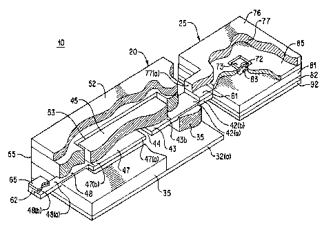
Fig. 2 is a cutaway perspective view of the condition
indicator assembly referenced in Fig. 1.
Fig. 2A shows a battery having a permanently connected
condition indicator assembly with the condition indicator
assembly in partial cross sectional view shown enlarged.
For the purposes of,the following discussing the
electrochemical cell or battery that is being measured will be
referred to as the «main cell's and the electrochemical cell that
generates the display will be called the ~~indicator cell's.
The invention is directed to a condition indicator assembly
(tester) which is electrically connected to and visually
displays the condition of a main cell or battery. The condition
indicator comprises an indicator cell which is a thin-film
electrochemical cell comprising an anode, a cathode, and an
electrolyte contacting at least a portion of both said anode and
cathode. The indicator cell has an anode and cathode of
different material and a,finite electromotive force (e.m.f.),
typically, greater than 100 millivolts, e.g., between about 100
millivolts and 1.5 volts. It has been determined in the present
invention that the indicator cell may be designed to have an
open circuit voltage which is either higher or lower than that
of the main cell being tested, if an auxiliary cell having a
finite electromotive force (e.m.f.) is connected in series with
3
CA 02231106 1998-03-04
WO 97/11376 PCT/US96/12910
the indicator cell to compensate for the difference in open
circuit voltage between indicator cell and main cell. That is,
one of the anode and cathode of the auxiliary cell is
electrically connected to one of the anode and cathode of the '
indicator cell. The remaining electrode of the auxiliary cell
and the remaining electrode of the indicator cell are
electrically connected in parallel to the main cell terminals.
During discharge of the main cell, reaction begins in the
visible electrode of the indicator cell and continues to remote
regions thereof. During discharge of the main cell being tested
the open circuit voltage of the condition indicator comprising
the indicator cell and the auxiliary cell is similar to the open
circuit voltage of the main cell, preferably within (plus or
minus) about 300 millivolts of the open circuit voltage of the
main cell.
In the circuit arrangement, depicted in Fig. 1, the
condition indicator 10 comprises an indicator cell 20 and an
auxiliary cell 25. The indicator cell 20 and the auxiliary
cell 25 are electrochemical cells having a finite electromotive
force (e.m.f.) of their own. In the circuit arrangement
depicted in Fig. 1 the open circuit voltage (OCV) of the
indicator cell 20 is lower than the open circuit voltage of main
cell 30. In this case the auxiliary cell anode 77 is
electrically connected to the indicator cell cathode 43, the
auxiliary cell cathode 83 is connected to the main cell cathode
145, and the indicator cell anode 47 is connected to the main
cell anode 115. (The anode of either the auxiliary cell 25 or
indicator cell 20 is defined as the electrode being oxidized and
thus releasing electrons. It should also be understood that ,
there are internal resistances associated with each of the main
cell 30, the indicator cell 20, and the auxiliary cell 25.) In
the circuit arrangement of Fig. 1, the open circuit voltage of
4
CA 02231106 1998-03-04
WO 97/11376 PCT/US96/12910
the indicator cell 20 becomes added to the open circuit voltage
of the auxiliary cell 25 so that the combined open circuit
voltage of the condition indicator 10 as a whole, i.e., between
~ cathode 83 of the auxiliary cell 25 and anode 47 of the
condition indicator cell 20 is about the same as the open
circuit voltage of the main cell 30. The capacity of the
indicator cell 20 is much less than the capacity of the main
cell 30 and the combined internal resistance of the indicator
cell 20 and auxiliary cell 25 is much greater than that of main
cell 30. The much higher resistance of the condition indicator
assembly 10 allows indicator cell 20 to discharge at a much
lower rate than the main'cell. This is required, since the
indicator cell 20 has a much smaller capacity compared to the
main cell. During discharge of the main cell 30, the ratio of
the current, iM, through the main cell to the current, iT,
through the indicator cell may be a constant so that the percent
depletion of one of the anode or cathode of the auxiliary cell
will be about the same as the percent depletion of one of the
anode or cathode of the main cell. A visual display showing the
percent depletion of one of the electrodes of the indicator cell
can thus be employed to reflect the state of charge of the main
cell 30.
In the circuit arrangement, depicted a.n Fig. 1A, the
condition indicator 10 comprises an indicator cell 20 and an
auxiliary cell 25. In the circuit arrangement depicted in Fig.
1A the open circuit voltage (OCV) of the indicator cell 20 is
higher than the open circuit voltage of main cell 30. In this
case the auxiliary cell cathode 83 is electrically connected to
the indicator cell cathode 43, the auxiliary cell anode 77 is
connected to the main cell cathode 145, and the indicator cell
anode 47 is connected to the main cell anode 115. In such
arrangement the open circuit voltage of the auxiliary cell 25
CA 02231106 1998-03-04
WO 97/11376 PCT/L1S96/12910
reduces the open circuit voltage of the open circuit voltage of
the indicator cell 20 so that the open circuit voltage of the
condition indicator 10 as a whole, i.e., between anode 77 of the
auxiliary cell 25 and anode 47 of the condition indicator cell '
20 is about the same as the open circuit voltage of the main
cell 30. The same effect in this case may also be achieved by
connecting anode 47 of indicator cell 20 to anode 77 of
auxiliary cell 25, connecting cathode 43 of the indicator cell
20~to cathode 145 of the main cell 30 and connecting cathode 83
of the auxiliary cell 25 to anode 115 of main cell 30.
Condition indicator 10 comprising an indicator cell 20 and
auxiliary cell 25 is shown in Fig. 2 in an arrangement
consistent with the circuit diagram of Fig. 1. Condition
indicator 10 may be permanently connected to a main cell 30
(Fig. 2A), such as a conventional alkaline cell, for example, by
integrating it into the label for the main cell. Since the open
circuit voltage discharge profile across the condition indicator
is about the same as the open circuit voltage discharge
profile of the main cell 30, the ratio of current flow through
the main cell to the current flow through the auxiliary cell
stays at nearly constant value. This can be so irrespective of
the load on the main cell. Thus, at any time during discharge
of the main cell, the percent depletion of one of a controlling
anode or cathode of either indicator cell 20 or auxiliary cell
25 will be about the same as the percent depletion of one of a
controlling anode or cathode of the main cell 30. (If the amount
of anode active material or cathode active material in either
the main cell 30 or indicator cell 20 is in excess, the
comparison of percent depletion between the two cells should be
made using the electrode containing active material not in
excess. The electrode not in excess is referred to herein as
the controlling electrode.?
6
CA 02231106 1998-03-04
WO 97/11376 PCT/US96/12910
Typically, the percent depletion (clearing) of the anode 47
of indicator cell 20 can be employed to reflect the percent
depletion of a controlling electrode in the main cell. This can
be used to provide a continual visual indication of the
condition (state of charge) of the main cell. The percent
active material remaining in the indicator cell 20 may be
visually discernible at any time during the life of the main
cell. For example, if the indicator anode 47 is being depleted,
the anode may be made visually discernible and a graphics scale
positioned next to that anode may indicate the percent charge
remaining in the main cell 30 and/or whether the main cell needs
to be replaced.
Condition indicator 10 may be connected in parallel with
main cell 30 being tested, for example, as illustrated in the
circuit diagram of Fig. 1. In Fig. 1 the main cell 30 is shown
schematically with negative terminal 115 and positive terminal
145. In use, when main cell 30 is connected to a load 38 and
discharges, current iL flows through the load 38, current iM
flows through the main cell 30 and current iT flows through
condition indicator 10 such that iL =iM + iT,. In the circuit
configuration of Fig. 1, 'if the main cell i;s a conventional AA
size alkaline cell having an internal resistance of about 0.1
ohm during normal operation, the combined internal resistance of
indicator cell 20 and auxiliary cell 25 is typically at least
about 10'' times, more typically between about 104 and 10' times
the internal resistance of main cell 30. It should be
appreciated that the total resistance of the condition indicator
may be adjusted by altering the internal resistance of each
of the indicator cell 20 and auxiliary cell 25 or by adding
resistors in series with these two cells.
7
CA 02231106 1998-03-04
WO 97/11376 PCT/LJS96/12910
In a preferred embodiment condition indicator 10 (tester
assembly) as shown in Fig. 2 comprises an indicator cell 20
electrically connected in series to an auxiliary cell 25 in the
manner corresponding to the circuit arrangement of Fig. 1. '
Condition indicator 10 (tester) has a thickness less than 100
mils (2.5 mm), preferably a thickness between about 2 and 100
mils (0.05 and 2.5 mm), more preferably a thickness between
about 2 and 15 mils (0.05 and 0.4 mm). Auxiliary cell 25 is a
miniature thin power source which at least partially drives
indicator cell 20. Main cell 30 may be a primary or secondary
battery and typically may be a conventional alkaline cell.
Condition indicator 10 may be integrated into the label for the
main cell 30, for example, by attaching it to the inside surf ace
of the label. Indicator cell 20 contains an anode 47 and
cathode 43 composed of different materials in contact with an
electrolyte. The indicator cell 20 and auxiliary cell 25
discharges linearly proportional to the discharge of the main
cell 30, irrespective of load 38. For example, indicator cell
20 can be calibrated so that during discharge of main cell 30
the percentage discharge of the either a controlling anode or
cathode of the indicator cell 20 will be about the same as the
percent discharge of a controlling electrode of main cell 30.
For usage of the main cell 30 at extremely high or low current
drain, i.e., greatly deviating from normal usage, the percent
discharge of the indicator cell 20 will be a function of the
percent discharge of the main cell, if not a linear function
thereof .
Indicator cell 20 (Fig. 2) is a miniature electrochemical
cell containing a cathode material 43 and anode material 47 ,
which are desirably spaced apart from each other, and which may
lie in the same plane. Cathode 43 and anode 47 are desirably
of different electrochemically active materials in contact with
8
i
CA 02231106 1998-03-04
WO 97/11376 ~ P~T/US96/12910
electrolyte resulting in a cell having a finite electromotive
force. Cathode 43 and anode 47 are thin coatings deposited
onto substrates 42 and 48, respectively. It. is desirable that
~ the material used for cathode 43 and cathode substrate 42 not be
reacta.ve in the ambient atmosphere or subject to corrosion. In
the embodiment shown in Fig. 2 a preferred cathode material 43
may of lambda Mn02 and a preferred anode mal::erial may be silver.
Anode substrate 48 is preferably conductive and preferably of
carbon and cathode substrate 42 is conductive. (It is possible
to use a nonconducting material for anode substrate 48, but a
conducting substrate is preferred and will be described herein.)
A conducting anode substrate 48 is used to prevent electrically
isolated islands of metal'from appearing on the substrate as
anode 47 is electrochemically stripped (cleared) from one end to
the other. A further requirement is that anode substrate 48 be
of a color that provides high contrast to t:he color of anode 47,
thus giving highly discernible visual indication of the clearing
of anode 47. A preferred arrangement of cathode 43 and anode 47
in relationship to each other and the underlying conductive
substrate is shown in Figure 2. A space 44 separates cathode 43
from anode 47 and also separates underlying conductive
substrates 42 from 48, as may be seen best i_n Fig. 2. Also,
there may be a film of insulating material :35 under conductive
substrates 42 and 48.
Conductive substrate 42 (Fig. 2) can extend beyond the edge
43 (b) of the overlying cathode material to forth extended
substrate portions 42(a). Similarly conduct:i.ve substrate 48 can
extend beyond the edge 47(b) of the overlying anode material to
form extended substrate portion 48(a). An adhesive is applied to
the surface of extended portions 42(a) and 48(a), thus forming
an adhesive border 55 around the periphery of conductive
substrates 42 and 48. Adhesive border 55 defines a window space
9
CA 02231106 1998-03-04
WO 97/11376 PCTlUS96/12910
53 over cathode 43 and anode 47. A layer of clear electrolyte
45 is applied in window space 53 so that it covers cathode 43
and anode 47. The end 48(b) of extended substrate portion 48(a)
protrudes from the anode side of cell 20. Similarly the end '
42(b) of extended substrate portion 42(a) protrudes from the
cathode side of cell 20. A piece of aluminum foil 65 is
attached to anode substrate end 48(b) using conductive adhesive
62 placed therebetween. Foil 65 serves to carry current from
substrate 48 to the battery negative terminal 115 (Fig. 2A).
Cathode substrate end 42(b) is covered on its top surface with
conductive adhesive 61. A transparent barrier film 52 is applied
over window 53 with the edges of the film in contact with
adhesive border 55. Thus, barrier film 52 is a protective film
which covers and tightly seals off electrolyte 45. Barrier film
52 is held in place by adhesive border 55. Indicator cell 20
may be secured to the casing of main cell 30 with a pressure
sensitive adhesive 32 applied the underside of the condition
indicator under insulating film 35.
Auxiliary cell 25 (Fig. 2) is desirably a thin flat power
cell. Auxiliary cell 25 has a thickness less than 100 mils (2.5
mm), preferably a thickness between about 2 and 100 mils (0.05
and 2.5 mm), more preferably a thickness between about 2 and 15
mils (0.05 and 0.4 mm). Auxiliary cell 25 contains a coating of
anode active material 77, a coating of cathode active material
83, and electrolyte layer 73 therebetween. The anode active
material 77 may be coated or laminated to a conductive substrate
76. Anode active material 77 contacts separator 72 filled with
electrolyte 73. Cathode active material 83 which may be coated
or laminated to a conductive substrate 81 is also in contact
with the electrolyte 73 contained within separator 72. The anode
and cathode conductive substrates, 78 and 81, respectively, may
typically be carbon coated aluminum or metal foil. A conductive
CA 02231106 1998-03-04
WO 97/11376 IaCT/CTS96/12910
adhesive 92 may be applied to the underside of auxiliary cell 25
in contact with the exposed surface of conducting substrate 81.
The auxiliary cell 25 is electrically connected to the indicator
cell 20 (Fig. 2) is electrically connected to by applying the
anode tab 77(a) of the auxiliary cell 25 so that it contacts
' conductive adhesive 61 on cathode substrate tab 42(b) of the
indicator cell 20. This electrically connects auxiliary anode
acta.ve material 77 with cathode 43 of indicator cell 20
consistent with the circuit diagram of Fig. 1. Connections to
main cell 30, typically a conventional alkaline cell, is
illustrated with reference to Figs. 2A. Auxiliary cathode active
material 83 becomes electrically connected to the positive
terminal 145 of main cell 30 through conductive adhesive 92
(Fig. 2) which connects auxiliary cathode 83 to the main cell
housing as shown in Fig. 2A. Foil tab 65 is pressed into
permanent contact with negative end cap 110 of the main cell
(Fig. 2A) so that conductive adhesive 62 contacts end cap 110.
Such connection places anode 47 of indicator cell 20 in
electrical contact with the negative terminal 115 of the main
cell 30.
Condition indicator 10 may be integrated onto the inside
surface of a film label 58 for the main cell. as illustrated in
Fig. 2A. Label 58 may desirably be a heat shrinkable film such
as polyvinylchloride or polypropylene. Condition Indicator 10
may be formed on one side'of the label by sequential printing or
lamination of each of the coatings that comprise the indicator
cell 20 and auxiliary cell 25. A layer of heat resistant
pressure sensitive adhesive, may be applied to the inside
surface of the label and the label with integrated condition
indicator may be applied to main cell 30 by wrapping it around
the cell housing. The ends of the label may then be heat shrunk
over the top and bottom shoulders 152 and 154, respectively, in
11
CA 02231106 2002-O1-10
conventional manner by subjecting the edges of the label to
sufficient heat to cause shrinkage.
In operation, when the main cell 30 discharges, indicator
a3node active material 47 discharges (clears). Anode active
material 47 disappears gradually from the portion of anode
active layer closest to cathode layer 43, namely, from end 47(a)
(Fig. 2). This provides a visually discernible fuel gauge
Effect. The amount of indicator anode remaining in cell 20 at
any time during the life of main cell 30 is readily visible
through transparent electrolyte 45. This enables easy
determination of the degree of discharge of the main cell by
~risual inspection through window 53 of the amount of anode 47
remaining in indicator cell 20. A calibrated graphics scale may
be provided adjacent indicator anode 47 to make it easier to
determine when anode 47 has been sufficiently depleted
:Lndicating that main cell 30 must be replaced.
The following materials can be used to construct condition
indicator 10: The indicator cell anode 47 may be composed of a
:silver coating (thickness between 500 and 1000 angstrom)
deposited on top of anode substrate 48 by sputtering or by
electron beam evaporation. Indicator cell anode substrate 48
and cathode substrate 42 may be composed of a carbon filled
polyethylene material (Velstat from 3M) Materials Inc (CMI).
i~lternatively, anode substrate 48 may be composed of an
:insulating plastic film such as ACLAR film
(polychlorotrifluoroethylene) from Allied Signal Co. or KALODFX*
:Film (polyethylene naphthalate) from ICI Americas coated with an
electronically conducting film such as indium tin oxide (ITO) or
~~onductive carbon coating. Alternatively, anode substrate 48
may be composed of an insulating material. Anode substrate 48
:has a thickness desirably between about 0.5 and 1 mil.
12
* Trade-Mark
CA 02231106 1998-03-04
WO 97/11376 PCT/US96/12910
The indicator cell cathode 43 is composed of a cathode
mixture, for example, containing cathode active material such as
V,OS or lambda MnOa . The cathode mixture cor~taining the Va05 or
lambda MnOa material can be prepared by mixing such material with
' conductive particulates for example, carbon, graphite or
metallic powder. The cathode mixture may be further mixed with
binder and solvent such as polyvinylidene i°luoride and
1-methyl-2-pyrrolidinone to form a coatable ink. The ink may
then be coated onto the cathode substrate 42 as a wet film of
0.2-2 mil thick and then'dried to forth the cathode.
The indicator cell electrolyte 45 (Fig. 2) may be prepared
by first forming an electrolyte solution composed of a mixture
of silver trifluoromethanesulfonylimide (AgTFSI), lithium
trifluoromethanesulfonylimde (LiTFSI) dissolved in
3-methylsulfolane solvent and then gelling the solution with
poly(vinylidene fluoride). Electrolyte 45 may be prepared by
mixing 8 parts by weight of the electrolyte solution with 3
parts by weight of poly(vinylidene fluoride). The mixture is
extruded at a temperature of about 140°C to the desired
thickness, preferably between about 1 and 4 mils (0.025 mm and
0.10 mm) and applied over the indicator cell anode 47 and
cathode 43.
The indicator adhesive frame 55 (Fig. 2) may be selected
from a wide range of pressure sensitive adhesives. A desirable
adhesive is a conventional butyl rubber based adhesive such as
polyisobutylene/isoprene copolymer adhesive available as Butyl
065 rubber adhesive from EXXON Co. Adhesive frame 55 desirably
has a thickness between about 1 and 2.5 mil (0.025 mm and 0.0625
mm). Indicator transparent barrier 52 may be desirably composed
of ACLAR (polychlorotrifluoroethylene) film. (Allied Signal Co.)
'B 3
CA 02231106 1998-03-04
WO 97/11376 PCT/US96/12910
of thickness between about 0.6 and 1 mil (0.015 and 0.025 mm) or
Kalodex film (Polyethylene naphthalate). Conductive adhesive 62
may desirably be a carbon filled conductive adhesive such as
that available under the trade designation ARCLAD conductive '
transfer adhesive from Adhesives Research Co. Adhesive coating
62 may desirably be about 0.5 mil (0.012 mm) thick. Foil
backing 65 may desirably be of aluminum foil between about 0.25
and 0.5 mil (0.006 and 0.012 mm) thick.
The materials used in the auxiliary cell 25 depends on the
open circuit voltage of the indicator cell. Materials for the
auxiliary cell 25 are selected so that the total open circuit
voltage across the condition indicator assembly 10 as a whole is
about the same as that of the main cell being discharged. Either
aqueous or organic electrolytes may be used in auxiliary cell
25. If an aqueous electrolyte is used, a typical auxiliary cell
cathode conductive substrate 81 may be composed of conductive
carbon-filled poly(vinylacetate)/poly(vinyl chloride) polymer
film (Rexham Graphics conductive plastic film no. 2664-Ol). As
above described conductive layer 81 is laminated to a layer 82
of aluminum foil. The conductive polymer film may desirably be
about 1 mil (0.025 mm) thick and the aluminum foil between about
0.25 and 0.5 mil (0.006 and 0.012 mm) thick. The auxiliary cell
cathode 83 is desirably composed of a printed coating containing
X% electrolytic manganese dioxide (EMD), (90 - X)% graphite, and
10% polyvinylchloride binder. Cathode active layer 83 may be
prepared by dispersing 3 parts by weight of the a mixture of EMD
and graphite in 7 parts by weight of aqueous 0.75% Carbopol 940
(B.F. Goodrich Co.) crosslinked acrylic acid copolymer and
adjusting the mixture to a pH of 10 with KOH and then adding
HALOFLEX 320 (ICI Americas - U.S. Resins Division) PVC latex in
sufficient amount that it comprises 10 wt.% of the final dried
cathode material. The mixture is then coated as a wet film (0.2
14
CA 02231106 1998-03-04
WO 97/11376 PCT/US96/12910
to 0.5 mil thick) onto carbon-filled polymer layer 81 and then
air dried to form dried cathode active layer 83.
Auxiliary cell separator 72 may be a nitrocellulose or
cellophane porous membrane of thickness about 1 mil (0.025 mm)
containing about 2-8 microliters of an elecarolyte solution 73
composed of about of 24 to 32% by weight aqueous ZnCl adjusted
to'a pH of 4 by adding ZnO. A seal 85 is provided between the
outer edges of anode 77 and cathode 83 to hold the auxiliary
cell together and prevent contaminants from entering the cell.
Seal 85 may suitably be formed of a heat sealable film of
polyvinylacetate/polyvinylchloride. Alternatively, it may be
composed of a butyl rubber pressure sensitive adhesive such as
Butyl 065 rubber from Exxon Co. Seal 85 is advantageously
between about 1 and 2 mil (0.025 mm and 0.05 mm) thick.
The auxiliary cell anode material 77 may be coated onto a
substrate 76 composed of conductive carbon-filled polyvinyl
acetate)/poly(vinyl chloride) polymer film (Rexham Graphics
conductive plastic film no. 2664-O1). Substrate 76 may be
laminated to a layer of aluminum foil (not shown) on the surface
of substrate 76 opposite anode material 77. The conductive
polymer film may desirably be about 1 mil (0.025 mm) thick and
the aluminum foil between about 0.25 and 0.5 mil (0.006 and
0.012 mm) thick. The auxiliary cell anode layer 77 may be a
coating composed of 90% anode powder, (e.g., zinc powder or
other metallic powder depending on the voltage needed) and 10%
styrene-butadiene copolymer (SBR) binder. Anode layer 77 may be
prepared by first dispersing 6.5 parts by weight Zn powder (5 to
7 micrometer particle size) in 3.5 parts by weight aqueous 1.25%
Carbopol 940 crosslinked acrylic acid copolymer gel (adjusted to
a pH of 12 with KOH). Then a styrene-butad:i.ene rubber latex
(ROVENE 5550 SBR latex from Rohm & Haas Co.) is added in amount
CA 02231106 2002-O1-10
:sufficient to yield 1 part by weight styrene-butadiene rubber
per 9 parts zinc in the final dry film. The mixture is then
coated as a wet film (0.5 to 1.5 mil thick) onto carbon-filled
polymer layer 76 and then air dried.
Auxiliary cell contact adhesive 61 and 92 may be selected
from a variety of conductive adhesives. A suitable adhesive 61
or 92 may be a conductive carbon-filled transfer adhesive
available as ARCLAD adhesive from from Adhesives Research Co.
~~uch adhesive may be coated to a thickness of about 0.5 mil
'(0.012 mm) over aluminum foil layer 82 forming adhesive layer
92. The same adhesive composition may be coated to a thickness
of about 0.5 mil (0.012 mm) forming adhesive layer 61 over
~~ndicator cathode substrate end 42(b).
Indicator backing adhesive 32 may be selected from a wide
variety of pressure sensitive adhesives. Desirably adhesive 32
is composed of a butyl rubber pressure sensitive adhesive such
as Butyl 065 rubber from Exxon Co.
The following are working examples of the tester described
with reference to Fig. 2:
Example 1
Working condition indicator assemblies 10 of the type
described in the preferred embodiment (Fig. 2) are constructed
and used to indicate the state of charge of conventional Zn/MnOz
(1.5 volt) AA alkaline cells discharged through various loads.
Indicator ells 20 as described with reference to Fig. 2
<~re prepared with the following components: The indicator cell
anode 47 is prepared by sputter-depositing 600 angstrom of
;silver onto conducting carbon filled substrates 48 (Velstat
carbon filled polyethylene from 3M Company). The anode area is
about 0.86 in. (2.2 cm.) by 0.2 in. (0.51 cm). The indicator
cell cathode 43 is formed by first preparing a cathode mixture
of 70:30 (by weight) of Vz05 and graphite. Then, 3 gm of this V,OS
16
* Trade-Mark
CA 02231106 1998-03-04
WO 97/11376 PCT/LTS96/12910
and graphite mixture is mixed with 0.45 g of polyvinylidene
fluoride (PVDF) and 4.5 g of 1-methyl-2-pyrolidinone to form an
ink. The ink is coated on substrate 42 (V:FLSTAT carbon filled
polyethylene) and dried at 150° C for 1 hr. in air to form a 1
mil thick cathode coating. The cathode area is about 0.2 in
r
(0.51 cm) by 0.2 in. (0.51 cm). The cathode is separated from
anode by a gap of about 0.05 in. (0.13 cm) within a 2.5 mil
(0.06 mm) thick butyl rubber pressure sensitive adhesive window
having an interior space about 0.7 in. long by 0.30 in. wide.
Anode and cathode are contacted by 2 mil thick transparent
electrolyte 45 about 0.61 in. long by about 0.2 in. wide
consisting of 0.5 M LiTFSI (lithium
trifluoromethanesulfonylimide) and 0.003M AgTFSI (silver
trifluoromethanesulfonylimide) in solvent and prepared as
previously described for the preferred embodiment. A 1 mil
thick KOLODEX polyethylene naphthalate) transparent barrier
film 52 about 1 in. long by 0.60 in. wide is used to seal the
indicator. Finished indicators are between about 6 and 7 mil
(0.15 and 0.18 mm) thick:
Auxiliary cells 25 of the type described with reference to
Fig. 2 are prepared with the following components. The
auxiliary cell cathode 83 is prepared by coating a manganese
dioxide layer containing electrolytic manganese dioxide (EMD) on
a conductive substrate 81 composed of Rexham Graphics no.
2664-O1 conducting carbon-filled plastic fz.lm as previously
described. The manganese dioxide coating i.s applied as a 0.5
mil thick wet film having dry composition which is 68~ ENm and
17 ~ graphite.
The auxiliary cell anode 77 is prepared by applying a zinc
coating on Rexham Graphics no. 2664-O1 conducting carbon-filled
plastic substrate as described in the preceding description. The
dry zinc anode has thickness of about 1 mil. and about 0.070 ins
(0.45 cm2) area to give capacity several fold in excess of that
17
CA 02231106 1998-03-04
WO 97/11376 PCT/US96/12910
of the cathode. The separator 72 is prepared employing 1 mil
thick cellophane film containing a about 6x10-' liter of pH 4 (281;
ZnCl,) electrolyte. Seal 85 is a 2 mil thick butyl rubber
pressure sensitive adhesive (Butyl rubber 065 adhesive from "
Exxon ) used to seal the auxiliary cell. Finished auxiliary
cells are about 8 mil thick and had alternating current
resistance measured at 1 kHz of about 2 k-ohm.
Indicator and auxiliary cells are connected to each other
in~series to form a condition indicator assemply 10 as shown in
Fig. 2. The completed condition indicator 10 in this example has
a thickness between about 6 and 8 mils (0.15 and 0.2 mm). The
condition indicator 10 is connected in parallel as shown in Fig.
1 and 2A) to the terminals of a fresh Zn/MnOa (1.5 volt) AA
alkaline cells using ARCLAD 0.5 mil thick conductive adhesive
(61 and 92) as previously described. The indicator cell 20 has a
positive electromotive force (e.m.f.). The open circuit voltage
across the condition indicator assembly 10 as a whole is about
the same as that of the main cell being discharged.
The AA cells are discharged from 1.5 to 0.8 volts through
load resistors of either 1 ohm, 4 ohm, 36 ohm, or 75 ohm, either
continuously or intermittently and the current through the
indicator cell 20 is about (0.5-2) x 10-camps. In all cases the
indicator anode clears in a gauge-like fashion to visually
reveal the underlying black conducting anode substrate 48, with
the clearing beginning from the end 47(a) closest to the cathode
and proceeding towards the opposite end of the cathode. The
amount of clearing correlates proportionally with the extent of
discharge of the AA cell. Thus the tester serves as an effective
state of charge indicator for the main cell.
The specific condition indicator assembly described in
this example can be employed advantageously to test the
condition of a conventional Zn/MnOs alkaline cell which may
operate typically with load resistance between about 1 and 1000
18
CA 02231106 1998-03-04
WO 97/11376 PCT/US96/12910
ohms. Application of the invention, however, is not intended to
be limited to alkaline cells but rather may be used effectively
to test the condition of any dry cell.
Example 2
Indicator cells 20 are prepared in the same manner as
descibed in Example 1, except the V~05 cathode mixture was
replaced with a different cathode mixture containing lambda MnO,.
A cathode ink is first prepared by mixing 3 g of a mixture of
LiMn,O, and graphite (70:30 by weight), 0.45 g of polyvinylidene
fluoride (PVDF) and 4.5 g of n-methylpyrrolidinone (NMP). The
cathode ink is coated onto substrate 42 (VELSTAT material) and
dried at 150° C in air for 1 hr. The LiMnaO, contained in the
dried in7t is converted into lambda MnO, by leaching the dried ink
on the substrate in 0.03M HaSO, for 30 minutes. After the acid
leaching, the cathodes are rinsed and dried in air for 1 hr.
The indicator cell 20 is assembled in the same manner described
in Example 1 but with the above described cathode being
employed. The indicator cell 20 of this example has an open
circuit voltage of about 0.5 volts.
The auxiliary cells',are prepared in the same manner as
described in Example 1, except a Pb anode is used. The Pb anode
can be prepared in the same manner as the Z:n anode, except Pb
powder is employed instead of Zn. The electrolyte used is 28%
ZnCl2 pH 4 staturated with PbClz. The auxiliary cell thus
prepared has a open circuit voltage (OCV) o;f-. about 1.05 volts.
The indicator cell and the auxiliary cell are connected in
series with each other as in Example 1 to form the condition
indicator assembly 10 connected to a fresh ;Zn/MnO~ (1.5V) AA
alkaline cell. The open circuit voltage ac:e-oss the condition
indicator assembly 10 is about the same as that of the AA cell.
19
CA 02231106 1998-03-04
WO 97/11376 PCT/LTS96/12910
During the discharge of AA cell, the condition indicator behaves
similar to that of Example 1. In all cases the indicator anode
clears in a gauge-like fashion to visually reveal the underlying
black conducting substrate 48, with the clearing beginning from
the end 47(a) closest to the cathode and proceeding towards the
opposite end of the anode. The amount of clearing correlates
proportionally with the extent of discharge of the AA cell.
Thus, the assembly 10 serves as an effective state of charge
indicator for the main cell.
Although the present invention has been described with
reference to specific embodiments and specific materials of
construction, it will be appreciated that other embodiments and
materials are possible without departing from the concept of the
invention, Therefore, the invention is not intended to be
limited to specific embodiments described herein, but rather the
scope of the invention is defined by the claims and equivalents
thereof .
i
1
2