Note: Descriptions are shown in the official language in which they were submitted.
CA 02231457 2001-04-03
1. .cope of the Invention
The present invention relates to a roll machine, e.g., a calender, having at
least
one nip or roll opening formed between a roll and a mating roll. The roll
includes a
roll body having an elastic layer on its periphery.
2. Discussion of Background Information
Calenders similar in general to the type described above are generally known,
e.g., in paper making to compress a web made of base paper produced by a paper
1 ~ machine. These devices are utilized to improve surface quality of the
paper web.
German Patent Application No. DE 195 06 301 A 1 shows a calender with both
a "hard" and a "soft" roll. The soft roll includes a two-layer covering made
of
synthetic material having an overall thickness of approximately 13 mm. The
inner
layer has a greater elasticity and less hardness than the outer layer.
Calenders of this type may be utilized to form super calenders, i.e., in which
a number of rolls are positioned on top of each other to form a
correspondingly large
number of nips or roll openings. The rolls, which are generally characterized
as "soft
rolls", consist of multiple stacks of paper or cotton sheets mounted on an
axis and
pressed together under high pressure.
2 0 Recently, the "Janus-Concept" in rolls has been disclosed, in which the
"soft
rolls" are provided coverings made of synthetic material. In this manner, the
roll body
1
CA 02231457 2001-04-03
can either be formed by a roll jacket, when using a deflection-guided roll, or
by a
massive core.
The above-discussed calenders can also be used to form "soft calenders." In
this case, generally only two to three rolls work against one another. For
soft
calenders, coverings made of synthetic materials are used almost exclusively
as roll
coating. The thicknesses of these coatings 'are greater than 1 cm. Because it
is
generally desirable to have added thickness in the roll coating as an
allowance for
truing the roll, the roll coatings are initially approximately 12.5 mm thick.
Over time,
the roll is generally trued so that the thickness is approximately 8.5 mm. So
that these
roll coverings can withstand the compressive strains in the nips, the
synthetic material
of the coverings are reinforced with fibers or other fillers. These
reinforcing materials
increase the elasticity modulus and form a certain, natural limit for
attainable surface
smoothness of the rolls.
Up to now, it has been assumed that when using a soft roll, the nip length,
i.e.,
in the run direction of the web, extends during operation, because the
pressing of the
mating roll against the elastic roll coating causes a flattening out or
indenting of the
elastic roll coating. With the greater nip length, it has been assumed that
the
compressive strain sinks with a constant line load. For example, when treating
a
material web in a "soft" roll opening formed by a soft roll and a hard mating
roll a
different outcome is achieved than when using a "hard" roll opening formed by
two
hard rolls working against each other. Thus, it is presumed that with an
approximately linear roll contact and, therefore, a very narrow nip length,
correspondingly high compressive strains are formed in the nip.
Further, using a nip formed with a soft roll has the advantage that, during
treatment, the material web is protected. For example, during glazing of a
paper web,
developments such as an increased black glazing in unlined, uncoated papers,
or an
-2-
CA 02231457 1998-03-06
P 16403. S02
increased greasiness in lined papers can be avoided. However, the side of the
paper
web lying adjacent the soft roll is in many cases somewhat impaired, e.g.,
smoothness
is decreased.
SUMMARY OF THE INVENTION
The present invention provides an improved surface quality during treatment
in the roll machine. Further, the present invention provides a roll machine of
the type
generally described above that includes an elastic layer that, in the radial
direction, is
very thin.
'Thus, the present inventibn moves away from the above-noted arrangement in
which the nip is lengthened during operation. T'he layer, in accordance with
the
present invention, is so thin that substantially only the upper surface is
elastic, and
deformation of the roll geometry, e.g., a flattening-out or indenting,
practically does
not occur.
The present invention was brought about by the following surprising discovery:
In one experiment, a roll jacket of elastic synthetic material was fitted with
a 120 p.m
thick hard chrome layer. The hard chrome layer was, as is possible with
chrome, very
smooth. With this arrangement, It was expected that the smoothness of the hard
chrome layer would be "impressed" into paper web, i.e., to correspondingly
increase
smoothness on the side of the paper web adjacent this soft roll. While this
arrangement achieved the expected increase in smoothness on the side of the
web
adjacent the soft roll, the glazing result was unexpected. In this regard, the
phenomena that was heretofore only known from calenders formed by two hard
rolls,
i.e., increased black glazing of unlined, uncoated papers and increased
mottling
(greasiness) in lined papers, unexpectedly occurred. These results, which have
been
traced to crushing the fibers in the calender, especially protruding, fibers,
really
shouldn't have happened. That is, the elastic roll was still generally soft
enough, even
-3-
CA 02231457 1998-03-06
P16403.S02
though the 120 ~m thick chrome layer does not provide the necessary stiffness.
While
other, and fewer, compressive tensions should have appeared in a hard roll
opening;
this was obviously not the case. Accordingly, this arrangement was abandoned
in
favor of another method.
The next arrangement reduced the thickness of the elastic layer on the upper
surface of the roll. Astoundingly, superb glazing results appeared again with
the
treatment of the paper web, even though, in accordance with the prior methods
of
observation, what should have occurred with the increase of the pressure
tensions in
the nip, caused by the decrease in the elastic layer's thickness, occurred in
the chrome
layer. However, this was not the case. Good smoothness values and a
corresponding
sealing resulted, without an increased black glazing or increased greasiness.
The roll
coatings previously used were considered "thin" in contrast to the paper rolls
that had
a truing reserve in the magnitude of several 10 cm. Even with these "thin"
roll
coverings of the prior art, lengthening of the nip was presumed. However, no
such
presumption is applicable with the "very thin" elastic layer in accordance
with the
present invention, e.g., which attain the desired results with layer
thicknesses clearly
under approximately 8 mm.
Due to the elastic layer in the local region, the soft roll preferably
demonstrates
a surface elasticity. However, with respect to the elasticity, the layer
demonstrates
practically the same behavior as the roll body in the macroscopic region. The
layer
chosen is thus so thin that locally protruding fibers of the paper web can be
pushed
into the layer without crushing or damaging of the fibers. Thus, increased
black
glazing or an increased mottling (greasiness) is substantially avoided.
Further,
because the layer is so thin, during operation, practically no other surface
form of the
roll occurs. This is substantially the same as when two hard rolls are
utilized. Thus,
the previously assumed flattening-out of the elastic or soft roll in the nip
region does
-4-
CA 02231457 1998-03-06
P16403.502
not occur. The nip length, i.e., without paper, substantially corresponds to
the length
of a hard roll nip formed between two hard rolls. Thus, in effect, the
arrangement
provides a calender with two hard rolls in which one of the surfaces is
elastic.
The roll body is preferably made of, e.g., steel or cast iron. The roll body
can
be, e.g., either a roll shell, if a deflection-guided roll is used, or it can
also be a
massive steel or cast iron core. In both cases, the roll body is rigid enough
to summon
and absorb the necessary compressive forces without resulting in a deformation
that
is worth mentioning. Thus, the desired proportions arise in this manner.
The thickness of the elastic layer preferably amounts to, e.g., approximately
4
mm or less, and in particular approximately 2.3 mm or less. With these thin
layers,
it is astounding, and surprising, that very good glazing results are attained.
Further,
these results are even better than that obtained with known roll machines,
i.e., the
arrangement provides good gloss and smoothness values while also substantially
avoiding black glazing and mottling (greasiness).
It is advantageous if the layer is formed from a material that demonstrates a
modulus of elasticity of approximately 4,000 N/mm2 or less. Further, the
"softer" the
layer material is, i.e., the better its elasticity, the smoother the surface
obtained and
the lesser the local resistance of the layer is on the surface of the roll
against the
material web. Because the layer is thin enough, it is supported to a
sufficient extent
by the roll body. In this manner, the previously assumed deformations of the
soft roll
are not observed.
The thickness of the layer is preferably selected such that, during operation,
the
roll experiences a same distribution of compressive strain as in prior art
machines
having a same line load, a same roll nip geometry, and a fiber reinforced
conventional
layer with an elasticity modulus of approximately 6,000 N/mm2 or more. The
layer
thickness can thus be changed together with the elasticity modulus of the
material.
-5-
CA 02231457 1998-03-06
P16403.S02
For example, the lower the elasticity modulus is, the thinner the layer
becomes. With
a thinner layer, then, the influence of the elasticity of the layer material
on the roll nip
geometry is less significant. Thus, the desired distribution of compressive
strain may
be obtained.
The thickness of the layer is preferably made smaller than a distance of a
shearing strain peak from an outer surface of the layer. Thus, the shearing
strain peak,
which is located within the elastic roll covering in conventional
arrangements, is
located in the roll body, i.e., radially inward. In this manner, the strains
on the layer
material forming the elastic layer are reduced. Further, as a rule, the roll
body is
ready, and able, to absorb the shearing strain peak without greater
difficulties. In this
manner, the strain on the layer is kept to a minimum and the durability of the
roll is
increased.
With a line load of approximately 200 N/mm, the nip length, calculated with
the web, preferably has a value greater than the thickness of the layer by a
factor of
at least approximately 3.5. However, because the general calculation methods
are
only valid when the coating thickness at least approximately corresponds with
the nip
length, the general calculation methods cannot be utilized with the present
invention.
A numerical process is available, e.g., with the aid of the finite-element-
method, to
establish the size. In this manner, it can be determined that the coating
thickness is
small enough to obtain the desired effects.
The layer is preferably formed from a synthetic material that is not
reinforced.
A synthetic material of this kind, i.e., without reinforcing fibers or
reinforcing fillers,
can generally only be stressed to a small extent. However, when the layer
thickness
is small enough, the desired resiliency can be obtained even with non-
reinforced
synthetic materials. The great advantage of a non-reinforced synthetic
material is that
its surface can be very smoothly shaped. That is, up to now, the degree of
smoothness
-6-
CA 02231457 2001-04-03
..
was limited because the fibers or fillers serving to reinforce affected the
surface
roughness. Further, the surface roughness generally varies with the order of
the size
of the fibers or fillers. Thus, without these additional materials, surface
roughness or
smoothness can be controlled based exclusively on the synthetic materials
utilized.
It is preferable that the thickness of the layer be limited to a value less
than
approximately 90% of the value forming a' stress ceiling for compressive
forces
prevailing in the roll nip. These compressive forces prevailing in the roll
nip are
either known or can be calculated. Because it either peels off the roll or is
damaged
during operation, the synthetic material that is not reinforced cannot be used
once it
reaches a certain thickness. If necessary, the precise limit may be determined
through
experiments. Thus, if a certain distance from the limit is maintained and the
synthetic
material layer is made thinner, then, one has a measure for how thick the
synthetic
material may be, and has a certain assurance that small disturbances will not
result in
damage to the synthetic material.
It is advantageous if the layer is composed of pure epoxy resin. For example,
epoxy resin, in an unreinforced state, has a relatively low modulus of
elasticity, and
it can be polished very smooth to obtain a high increase in the smoothness of
the
treated material web.
The layer is preferably composed of a sprayable synthetic material and is
sprayed onto the roll body. By spraying, a relatively good bonding of the
synthetic
material with the roll body results. Further, the relatively thin layers can
be obtained
to produce a roll covering, which locally, i.e., in the microscopic region,
has the
necessary elasticity, but globally, i.e., in the macroscopic region, has no
mentionable
flexibility that can lead to a deformation of the roll.
In another advantageous embodiment, the layer may be formed as a lacquer
layer. In this manner, a certain elasticity is provided only on the surface of
the roll.
CA 02231457 1998-03-06
P 16403. S02
Further, lacquer layers are generally quite thin, so that the main strain may
be actually
absorbed by the roll core. The thinner the elastic layer is, the less it is
pressed during
operation, and the less heat develops. Thus, the temperature created by the
pressing
can be better controlled so that the temperature in the roll nip can be better
adjusted.
The coating, i.e., the elastic layer, may be stressed to a lesser degree by
higher
temperatures. In this case, the calender may b~e considered a thickening
calender, i.e.,
a roll machine with two hard rolls forming the nip, and in which one of the
two hard
rolls is lacquered.
In an alternative embodiment, the layer may be formed by a shrink tube. A
shrink tube of this kind may be pushed over the roll body and then, using
heat, shrunk
down onto the roll body. Thus, the elastic layer on the surface of the roll is
created
relatively quickly and at the same time is reliably connected to the roll
body. It is also
possible to replace the elastic layer without a problem. To replace the layer,
the
shrinkage tube is opened by slitting the jacket and then removing it. The roll
body is
then ready for a new shrinkage tube. If appropriate, the new tube may be trued
and
smoothly sanded.
The surface of the layer preferably is sanded to a roughness value of
approximately 0.1 pm or less. Smooth surfaces of this kind can be obtained
with thin
layers. Since the roughness of the roll is "impressed" in the material web,
the
smoother the surface is, the smoother the processed material web becomes. With
the
use of epoxy resin, a roughness of approximately 0.05 ~m may be obtained.
Accordingly, the present invention is directed to a roll machine that includes
a roll having a roll body and an elastic layer located on a periphery of the
roll body,
and a mating roll. At least one roll nip is formed between the roll and the
mating roll,
and the elastic layer has a radial thickness less than approximately 8 mm.
_g_
CA 02231457 1998-03-06
P16403.S02
In accordance with another feature of the present invention, the elastic layer
provides a surfaceelasticity in a local region, and provides a rigidity
substantially
similar to the roll body in a global region.
In accordance with another feature of the present invention, the roll body is
composed of one of steel and cast iron.
In accordance with another feature of the present invention, the radial
thickness
of the elastic layer is approximately 4 mm or less.
In accordance with still another feature of the present invention, the radial
thickness of the elastic layer is approximately 2.3 mm or less.
In accordance with a further feature of the present invention, the elastic
layer
includes a modulus of elasticity of approximately 4,000 N/mm2 or less. Still
further,
the radial thickness of the elastic layer is selected such that a compressive
stress
distribution occurring in the roll during operation under an operating line
load exerted
on an operating roll nip geometry is substantially the same as a test
compressive stress
distribution in a test roll under a test line load, substantially similar to
the operating
line load, exerted on a test roll nip geometry, substantially similar to the
operating roll
nip geometry, and the test roll further including a fiber-reinforced material
layer
having a modulus of elasticity of approximately 6,000 N/mm2 or more.
In accordance with another feature of the present invention, the radial
thickness
of the elastic layer is less than a distance of a shearing stress peak from an
outer
surface of the elastic layer.
In accordance with still another feature of the present invention, the roll
machine also includes a device for exerting a line load of 200 N/mm at the
roll nip.
A length of the roll nip, relative to a web travel direction, while pressing
the web, is
greater than the radial thickness of the elastic layer by a factor of at least
approximately 3.5.
-9-
CA 02231457 2001-04-03
In accordance with a further feature of the present invention, the elastic
layer
is composed of a non-reinforced synthetic material. Further, the radial
thickness of
the elastic layer is selected to be less than or equal to a value less than
approximately
90 % of a value forming a stress limit in compressive strains prevailing in
the roll nip.
In accordance with another feature of the present invention, the elastic layer
is composed of pure epoxy resin.
In accordance with a still further feature of the present invention, the
elastic
layer is composed of a sprayabte synthetic material that is sprayed onto the
roll body.
In accordance with another feature of the present invention, the elastic layer
is composed of a lacquer layer.
In accordance with another feature of the present invention, the elastic layer
includes a shrinkage tube.
In accordance with still another feature of the present invention, a surface
of
the elastic layer is sandable to a roughness value of approximately 0.1 ~m or
less.
The present invention is directed to a roll for a roll machine that includes a
roll
body and an elastic layer located on a periphery of the roll body. The elastic
layer has
a radial thickness of less than 8 mm.
The present invention is directed to a process for forming a roll machine. The
roll machine includes a roll having a roll body and a mating roll, and the
process
includes covering the roll body with an elastic layer having a radial
thickness less than
approximately 8 mm and pressing the roll and the mating roll together to form
a press
nip.
In accordance with another feature of the present invention, the covering of
the
roll body includes spraying a synthetic material coating on the roll body.
In accordance with another feature of the present invention, the covering of
the
roll body includes applying a shrink tube over the roll body and applying heat
to the
- lo-
CA 02231457 1998-03-06
P 16403. S02
shrink tube. In this manner, the shrink tube is reduced in size to fit the
roll body.
Further, the process includes smoothing the surface of the coating to a
roughness
value of approximately 0.1 pm or less.
In accordance with still another feature of the present invention, the
covering
of the roll body includes applying a lacquer layer of an epoxy resin material.
In accordance with a further feature' of the present invention, the process
includes forming the elastic layer from a non-reinforced synthetic material.
In accordance with a still further feature of the present invention, the
process
includes forming the elastic layer from an epoxy resin material.
In accordance with still another feature of the present invention, the process
includes forming the roll body from one of steel and cast iron.
In accordance with another feature of the present invention, the process
includes selecting the radial thickness of the elastic layer such that a
compressive
stress distribution occurring in the roll during operation under an operating
line load
exerted on an operating roll nip geometry is substantially the same as a test
compressive stress distribution in a test roll under a test line load,
substantially similar
to the operating line load, exerted on a test roll nip geometry, substantially
similar to
the operating roll nip geometry, and the test roll further including a fiber-
reinforced
material layer having a modulus of elasticity of approximately 6,000 N/mm2 or
more.
In accordance with still another feature of the present invention, the process
includes selecting a radial thickness of the elastic layer to be less than a
distance of
a shearing stress from an outer surface of the elastic layer.
In accordance with yet another feature of the present invention, the process
includes selecting a radial thickness of the elastic layer to be less than or
equal to a
value less than approximately 90 % of a value that forms a stress limit in
compressive
strains prevailing in the roll nip.
-tt-
CA 02231457 1998-03-06
P 16403. S02
Other exemplary embodiments and advantages of the present invention may
be ascertained by reviewing the present disclosure and the accompanying
drawing.
BRIEF DESCRIPTION OF THE DRAWINGS
The present invention is further described in the detailed description which
follows, in reference to the noted plurality of drawings by way of non-
limiting
examples of preferred embodiments of the present invention, in which like
reference
numerals represent similar parts throughout the several views of the drawings,
and
wherein:
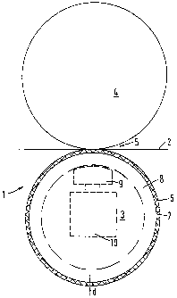
Figure 1 illustrates a schematic view of a calender with two rolls;
Figures 2a and 2b illustrate isolines of a shearing strain to compare a very
thin
elastic layer to an elastic layer with conventional layer thickness;
Figure 3 illustrates the progress of the shearing strain substantially in a
radial
direction; and
Figure 4 illustrates comparison of calculated contact widths.
DETAILED DESCRIPTION OF THE PRESENT INVENTION
The particulars shown herein are by way of example and for purposes of
illustrative discussion of the embodiments of the present invention only and
are
presented in the cause of providing what is believed to be the most useful and
readily
understood description of the principles and conceptual aspects of the present
invention. In this regard, no attempt is made to show structural details of
the present
invention in more detail than is necessary for the fundamental understanding
of the
present invention, the description taken with the drawings making apparent to
those
skilled in the art how the several forms of the present invention may be
embodied in
practice.
Schematically depicted in Figure 1 is a calender I utilized to treat a
material
web 2, e.g., paper. Calender 1 includes two rolls 3 and 4 that form a roll nip
-12-
CA 02231457 2001-04-03
(opening) S between them. During operation, rolls 3 and 4 are pressed together
with
devices that are generally known, and therefore, not depicted here in any
detail here.
Furthers material web 2 is treated under the pressure exerted in roll nip 5.
This
pressure treatment can lead to a compression of material web 2, but is also
used to
improve surface quality of material web 2.
Because roll nip 5 is formed between an elastic surface 6 of roll 3 and roll
4,
roll nip S may be referred to as a "soft" roll nip. Because roll 3 has a very
thin layer
7 of an elastic material formed on its periphery, surface 6 is elastic. Thin
layer 7 may
be deposited on a roll body 8 of roll 3. Roll body 8 may be a massive roll
core made
of steel or cast iron, e.g., chilled iron or gray iron. Alternatively, as
depicted with the
dashed-line, roll body 8 may be formed as a roll ,jacket of a detlection
adjustment
roll. In this event, roll body 8 may be supported by pressure elements 9
arranged on
a carrier 10. Pressure elements 9 may be utilized to impart pressure against
the
inside surface of roll body 8 against roll 4.
Roll 4 is a hard roll, i.e., a roll that is of an inflexible design, and may
be
composed of, e.g., steel or cast iron. To improve smoothness of the surface of
roll 4,
a hard chrome layer or another hard and smooth layer can be deposited on roll
4 in a
known manner.
Elastic layer 7 on soft roll 3 is depicted in Figure 1 in an exaggerated
manner
to facilitate discussion and understanding of the present invention. With
conventional
soft rolls, the thickness of the outer layer is generally approximately 12.5
mm. The
surface would then be trued to thicknesses of about 8 mm if damages or
markings
occurred during operation.
In accordance with the present invention, the thickness d of elastic layer 7
of
roll 3 is considerably less than the conventional designs. In other words,
layer 7 is a
very thin layer having a thickness d of approximately 1.75 mm. Further, the
modulus
-13-
CA 02231457 1998-03-06
P 16403. S02
of elasticity for layer 7 is approximately 3,500 N/mm2. Still further, layer 7
may be
composed of an epoxy resin that may be sprayed onto the outer surface of roll
body
8. Thus, layer 7 applied in this manner is free of reinforcing fibers or other
reinforcing fillers. Thus, surface 6 of layer 7 may be sanded to a very smooth
finish.
In this manner, the side of material web 2 lying adjacent to soft roll 3
obtains
exceptional gloss and smoothness values. Further, because the layer does not
include
reinforcing fibers or fillers, a diminished modulus of elasticity can be used
as
compared to that of conventional roll coverings, which are generally in the
order of
6,000 to 8,000 N/mm2, and particularly 6,900 N/mm2.
Since thickness d of layer 7 is very small, surface 6 of roll 3 is barely
deformable, at least in the macroscopic (global) region. Even during
operation, the
shape of the roll is determined by the shape of roll body 8. Thus, with the
present
invention, the known larger flattening-out or indenting of the soft rolls
during
operation can be substantially dismissed with relative certainty.
Despite the very thin layer 7, surface 6 of soft roll 3 is elastic enough to
allow
deformation in the microscopic (local) region. For example, in contrast to the
arrangement of two hard rolls, if fibers protrude from the surface of paper
web 2, the
local elasticity of surface 6 flattens the protruding fibers in the roll nip 5
without
crushing them. Thus, the present invention substantially avoids the known
developments of the black glossing or mottling (greasiness) of web 2 as it
passes
through roll nip 5.
As noted above, thickness d of layer 7 may be very thin. In fact, it is
sufficient
to deposit the layer material, e.g., an epoxy resin, like a lacquer such that
thickness d
lies in the order of approximately a few tenths or even approximately a few
hundredths of a millimeter. Alternatively, layer 7 may be formed with a shrink
tube
having an interior diameter proportioned to the external diameter of roll body
8. In
- 14-
CA 02231457 1998-03-06
P 16403. S02
this manner, the shrink tube may be pushed onto unlayered roll body 8. When
heat
is applied to the shrink tube, e.g., hot air, the tube shrinks and positions
itself evenly
over the surface of roll body 8. Then it is only necessary to smooth surface
6.
Due to the thin thickness of layer 7, if surface 6 has damages or markings,
the
truing reserves are exhausted. However, this is not critical. For example, in
the case
of a shrinkage tube with damage or markings, 'the old shrinkage tube may be
cut open
and removed and a new one is put on. In the case of a lacquered surface with
damages and markings, the roll can be lacquered anew. Both replacements
methods
proceed relatively quickly. Further, even when the epoxy resin or another
synthetic
material is sprayed on very thickly, the desired surface quality may be
achieved
relatively quickly by a renewed spraying.
In an advantageous embodiment of the present invention, thickness d of layer
7 is approximately 4 mm. It is also generally applicable that the modulus of
elasticity
must rise with increasing thickness d, so that layer 7 can withstand the
compressive
strains prevailing in roll nip 5.
Calculations were performed in order to compare soft roll 3 having very thin
layer 7 to a conventional roll having a thicker layer. Since thickness d of
layer 7 is
markedly less significant than the contact length of material web 2 with rolls
3 and 4,
the known calculations of the prior art, e.g., Hertz, cannot be considered
accurate,
and, thus, are not utilized in accordance with the present invention. However,
with
discrete procedures, e.g., in accordance with the method of finite elements,
the stress
distributions can be calculated in the rolls. In the present case, the
calculations were
performed as described in the dissertation by Rolf van Haag "On the
Compressive
Stress Distribution and the Paper Compression in the Roll Opening of a
Calender",
Darmstadt, 1993.
- IS -
CA 02231457 1998-03-06
P16403.S02
Figures 2a and 2b show isolines of shearing stresses associated in layer
thicknesses 7 and 7' in accordance with the present invention and with the
conventional design of the prior art, respectively. These calculations yield
the
following figures:
Present Conventional
Invention Calender
Diameter of Hard Roll 4, 4' 459 mm 459 mm
Diameter of Soft Roll 3, 3' 415 mm 415 mm
Line load 200 N/mm 200 N/mm
Paper Thickness in the Inlet 72 pm 72 pm
Thickness of Layer 7, 7' 1.75 mm 12.5 mm
Modulus of Elastici 3,500 N/mm2 6,900 N/mm2
From the obtained results, the shearing stresses in both cases look similar.
However, it further becomes obvious that, with the very thin layer 7 depicted
in
Figure 2a, the shearing stress peak lies outside layer 7, and is moved into
roll body 8.
In contrast, the conventional case shows the shearing stress peak located in
the middle
of elastic layer T. The location of the shearing stress is more clearly
depicted in
Figure 3 which shows a plot of the Y-coordinate, as depicted in Figures 2a and
2b,
and the shearing strain. The shearing strain is illustrated in Figure 2a as
line A
located in a substantially radial direction of soft roll 3. The dashed line in
Figure 3
shows the border between very thin layer 7 and roll body 8. As shown, the
maximum
shearing stress occurs at approximately 2.42 mm, and thickness d of layer 7
only
amounts to approximately 1.75 mm. Thus, the maximum shearing stress is located
- 16-
CA 02231457 1998-03-06
P 16403. S02
within roll body 8. Because roll body 8 is formed of, e.g., steel or cast
iron, it is
therefore able to absorb the maximum shearing stress without a problem.
Figure 4 illustrates a further comparison of the very thin layered roll of the
present invention and the conventional roll having a thickness d of 12.5 mm.
The profile (plot) marked by squares depicts a compressive strain curve for a
conventional coating having a thickness of 12:5 mm, a modulus of elasticity of
6,900
N/mm2, and a line load of 200 N/mm. Using the same coating except with a
thickness
of approximately 1.75 mm, the profile marked by the circles would result.
Thus, as
shown, the maximal compressive strain would increase from approximately 54 to
approximately 62 N/mm2. However, because in this region the stabilities of the
coating are reached or exceeded, this type of coating is not desired.
The present invention utilizes resin as a coating because its modulus of
elasticity is markedly less than the prior art coating, i.e., approximately
3,500 N/mm2.
Thus, use of resin as the coating provides favorable conditions, e.g., with
respect to
distribution of the shearing stresses. For example, as the profiled marked by
triangles
shows, the curves of the thick, harder coating (squares) and the thin, soft
(resin)
coating (triangles) are almost congruent.
Because the very thin resin coatings can be sanded much smoother than the
conventional coatings, and because the resin coating develops less heat during
pressing, which in some circumstances can be harmful to the coating, some
clear
advantages for glazing are achieved. In this regard, it is interesting that
the nip
lengths are the same in each case, and the influence of the paper web is
apparent.
As discussed above, if a very thin coating is used, reinforcing fibers or
reinforcing fillers are unnecessary in the coating. In addition to the
advantage of
achieving a very smooth surface 6 having a roughness of approximately 0.05
Vim, the
lack of reinforcing fibers or fillers enables the advantage that handling of
the synthetic
- i7-
CA 02231457 1998-03-06
P 16403. S02
material during application to the roll body significantly simpler. Thus,
materials are
saved and finishing costs are thereby reduced. Further, while finishing costs
are
reduced, a marked improvement in quality during the glazing of paper and other
material webs is achieved.
It is noted that the foregoing examples have been provided merely for the
purpose of explanation and are in no way to'be construed as limiting of the
present
invention. While the present invention has been described with reference to a
preferred embodiment, it is understood that the words which have been used
herein
are words of description and illustration, rather than words of limitation.
Changes
may be made, within the purview of the appended claims, as presently stated
and as
amended, without departing from the scope and spirit of the present invention
in its
aspects. Although the present invention has been described herein with
reference to
particular means, materials and embodiments, the present invention is not
intended
to be limited to the particulars disclosed herein; rather, the present
invention extends
to all functionally equivalent structures, methods and uses, such as are
within the
scope of the appended claims.
-ia-