Language selection

Search

Patent 2231476 Summary

Third-party information liability

Some of the information on this Web page has been provided by external sources. The Government of Canada is not responsible for the accuracy, reliability or currency of the information supplied by external sources. Users wishing to rely upon this information should consult directly with the source of the information. Content provided by external sources is not subject to official languages, privacy and accessibility requirements.

Claims and Abstract availability

Any discrepancies in the text and image of the Claims and Abstract are due to differing posting times. Text of the Claims and Abstract are posted:

  • At the time the application is open to public inspection;
  • At the time of issue of the patent (grant).
(12) Patent: (11) CA 2231476
(54) English Title: IMPROVED PILOT AND NOZZLE ASSEMBLY
(54) French Title: ASSEMBLAGE AMELIORE COMPRENANT UNE VEILLEUSE D'ALLUMAGE ET UN INJECTEUR
Status: Term Expired - Post Grant Beyond Limit
Bibliographic Data
(51) International Patent Classification (IPC):
  • F23D 14/26 (2006.01)
  • F23D 14/06 (2006.01)
  • F23D 14/10 (2006.01)
  • F23D 14/48 (2006.01)
  • F23G 7/08 (2006.01)
(72) Inventors :
  • RAJEWSKI, ROBERT KARL (Canada)
(73) Owners :
  • TORNADO COMBUSTION TECHNOLOGIES INC.
(71) Applicants :
  • TORNADO COMBUSTION TECHNOLOGIES INC. (Canada)
(74) Agent: LAMBERT INTELLECTUAL PROPERTY LAW
(74) Associate agent:
(45) Issued: 2008-07-29
(22) Filed Date: 1998-03-06
(41) Open to Public Inspection: 1999-09-06
Examination requested: 2003-03-03
Availability of licence: N/A
Dedicated to the Public: N/A
(25) Language of filing: English

Patent Cooperation Treaty (PCT): No

(30) Application Priority Data: None

Abstracts

English Abstract

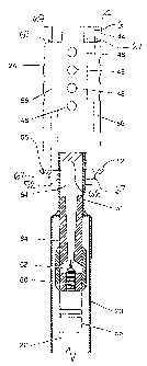
A nozzle tor a pilot light tor a flare stack, the nozzle being formed of a housing defined by an encircling cylindrical wall, with radially extending openings formed circumferentially around the encircling wall, and is made of material resistant against breakdown in a sour gas environment at temperatures at least less than 1200°C, preferably 98% by weight alumina ceramic. A cage holds the nozzle, which includes a base plate having a central aperture and first and second sides, a tube extending into the aperture from the first side of the base plate and fixed to the base plate, and plural retainers extending from the base plate and enclosing the nozzle. To form a pilot for a flare stack, a gas conduit is connected into an interior cavity of the nozzle. The cage is attached to a flame stack. The retainer members pass through the nozzle to protect the retainer members from the corrosive environment in which the pilot operates.


French Abstract

Le présent abrégé a trait à un injecteur conçu pour une veilleuse d'allumage de torche, l'injecteur étant constitué d'un logement délimité par une paroi cylindrique d'encerclement munie d'ouvertures radiales aménagées tout autour de sa périphérie, ledit injecteur étant fait d'un matériau résistant à la rupture dans un environnement de gaz sulfureux à des températures au moins inférieures à 1 200 degrés C, et composé, de préférence, de 98 % en poids de céramique d'alumine. Une cage maintient l'injecteur, qui inclut un socle pourvu d'une ouverture centrale ainsi que d'un premier et d'un second côtés, un tube se prolongeant dans l'ouverture à partir du premier côté du socle et étant fixé au socle, et plusieurs dispositifs de retenue se prolongeant à partir du socle et enfermant l'injecteur. Pour constituer la veilleuse de la torche, un conduit de gaz est relié à une cavité intérieure de l'injecteur. La cage est fixée à une torche. Les éléments de retenue traversent l'injecteur, ce qui les protège de l'environnement corrosif dans lequel la veilleuse fonctionne.

Claims

Note: Claims are shown in the official language in which they were submitted.


10
THE EMBODIMENTS OF THE INVENTION IN WHICH.AN EXCLUSIVE
PROPERTY OR PRIVILEGE IS CLAIMED ARE DEFINED AS
FOLLOWS:
1. A pilot for a flare stack, the pilot
comprising:
a nozzle made of material characterized by
being resistant against breakdown in a sour gas
environment at temperatures below 1200°C, the nozzle
having an encircling wall defining an interior cavity
and first and second ends;
a plurality of openings formed in the
encircling wall and extending radially through the
encircling wall, the openings being disposed
circumferentially around the encircling wall between
the first and second ends;
a base plate having a central aperture and
first and second sides;
plural retainer members extending from the
base plate and securing the second end of the nozzle
to the base plate;
a gas conduit connected into the interior
cavity of the nozzle through the central aperture in
the base plate;
ignition means disposed adjacent the nozzle
for igniting gas supplied to the nozzle through the
gas conduit; and
the retainer members passing through
longitudinal holes formed in the encircling wall.
2. The pilot of claim 1 in which the retainer
members extend from the first end to the second end of
the nozzle.

11
3. The pilot of claims 1 or 2 in which the
longitudinal holes extend from the first end to the
second end of the nozzle.
4. The pilot of claims 1, 2 or 3 in which the
nozzle is made of ceramic.
5. The pilot of claim 4 in which the ceramic
is silicon nitride.
6. The pilot of any of claims 1-5 further in
combination with a flare stack and a frame assembly
for supporting the pilot on the flare stack.

Description

Note: Descriptions are shown in the official language in which they were submitted.


CA 02231476 1998-03-06
1
TITLE OF THE INVENTION:
Improved Pilot and Nozzle Assembly
NAME OF INVENTOR:
Robert Karl Rajewski
FIELD OF THE INVENTION
This invention relates to nozzles and pilots
used in the burning of gas.
BACKGROUND AND SUMMARY OF THE INVENTION
The inventor has been a pioneer in the
development of ceramic nozzles for use in oilfield
applications. These nozzles show much greater
resistance to corrosion than metal nozzles.
One of the inventor's designs=is shown in
United States patent no. 5,634,788 (issued June 3,
1997). In this design, a ceramic nozzle, preferably
made from alumina ceramic is held by a cage of metal
retainer members. The cage assists in maintaining the
integrity of the nozzle, which tends to be more likely
to crack than a metal nozzle. While this design has
proven satisfactory, the metal retainers are exposed
to the highly corrosive environment of the nozzle, and
this may cause failure of the retainers.
SUMMARY OF THE INVENTION
It is therefore an object of this invention
to provide a pilot and nozzle, in which the nozzle is
secured by a cage which is not exposed to the highly
corrosive environment in which the nozzle usually
operates.

CA 02231476 1998-03-06
2
There is therefore provided in accordance
with an aspect of the invention, a pilot for a flare
stack, the pilot comprising:
a nozzle made of material characterized by
being resistant against breakdown in a sour gas
environment at temperatures below 1200 C, the nozzle
having an encircling wall defining an interior cavity
and first and second ends;
a plurality of openings formed in the
encircling wall and extending radially through the
encircling wall, the openings being disposed
circumferentially around the encircling wall between
the first and second ends;
a base plate having a central aperture and
first and second sides;
plural retainer members extending from the
base plate and securing the second end of the nozzle
to the base plate;
a gas conduit connected into the interior
cavity of the nozzle through the central aperture in
the base plate;
ignition means disposed adjacent the nozzle
for igniting gas supplied to the nozzle through the
gas conduit; and
the retainer members passing through
longitudinal holes formed in the encircling wall.
The retainer members and longitudinal holes
preferably extend from the first end to the second end
of the nozzle so that the structural portions of the
retainer members are entirely encased within the
nozzle. The nozzle is preferably made of silicon
nitride ceramic.

CA 02231476 1998-03-06
3
The pilot is used in conjunction with a
flare stack and a frame assembly for supporting the
pilot on the flare stack.
BRIEF DESCRIPTION OF THE DRAWINGS
There will now be described preferred
embodiments of the invention, with reference to the
drawings, by way of illustration, in which like
numerals denote like elements, and in which:
Fig. 1 shows a schematic of a flare stack
supporting a pilot and nozzle according to the
invention;
Fig. 2 is a side view schematic of a pilot
according to the invention;
Fig. 3 is a first cross-section of a nozzle
according to the invention for use in particular in
association with the pilot of Figs. 1 and 2;
Fig. 4 is a second cross-section of a nozzle
according to the invention for use in particular in
association with the pilot of Figs. 1 and 2;
Fig. 5 is a top view of the nozzle of Figs.
3 and 4; and
Fig. 6 is a section through a pilot
according to the invention showing a gas supply system
for the pilot.
DETAILED DESCRIPTION OF PREFERRED EMBODIMENTS
Referring to Fig. 1, there is shown a pilot
generally shown at 10 for a flare stack 12 such as is
used to flare gas at an oil well. The flare stack 12
may be supported by guy wires (not shown) in
conventional fashion and has a gas supply inlet 13
mounted at 45 . A rail 14 (2" x 1" HSS) running
parallel to and spaced from the flare stack 12 is

CA 02231476 1998-03-06
4
supported on supports 16 (1/,"x3 "x6" ), with a portion of
the rail near the top tilted towards the flare stack
12. The pilot 10 has supports 18 terminating in
sleeves 20 that slide on the rail 14. The pilot 10 is
pulled up and down the stack on the rails 14 using
cable 15, enclosed pulley 17 and winch 19.
Pilot 10 includes a high pressure flexible
gas supply line 22 connected to a high pressure source
of gas (not shown) and that terminates in a nozzle 24
held in a frame or cage which is shown in more detail
in Fig. 6. The gas supply line 22 is supported within
the pilot by conduit 23 (for example 2 inch 304L SS
pipe) attached to supports 18. Conduit 23, supports
18, sleeves 20, rail 14 and supports 16 together form
means for attaching the cage and nozzle 24 to flare
stack 12. The pilot 10 is moved into a shroud 25 at
the top of the flare stack and a flame is kept burning
constantly in the nozzle 24 so that should for any
reason the gas being flared through the flare stack
stop burning, then the gas will be immediately
ignited.
Also shown in Fig. 1 is a general
arrangement for an ignition control system for use
with the improved nozzle and pilot according to the
invention. Control and battery power source enclosure
30, which is of conventional construction, is mounted
on a wall of a building 28 a minimum distance from the
flare stack 12 as required by regulations. A hot
ignition wire 31 (#16/4 Teck T" cable) extends from the
control enclosure 30 to a conventional electrical
junction enclosure 34 on the flare stack 12 and then
(for example as a #16/4 Teck T"" cable) along the flare
stack to transformer and electrical junction enclosure
33. A main control panel 32 of conventional

CA 02231476 1998-03-06
construction is connected via a #16/4 Tech T" cable to
the control enclosure 30.
Referring now to Fig. 2, hot wire 35 leads
from the transformer enclosure 33 to an ignition
5 chamber 36 in which is a conventional spark plug (for
example a CJ6 spark plug). The ignition chamber 36
opens into a flash tube 37 (for example a 1 inch 304L
SS pipe), which lies along the conduit 23 and is
fastened to the conduit 23 by U-bolts 38. The flash
tube 37 terminates at a curved end 38, remote from the
transformer enclosure 33, that curves in towards an
opening in the nozzle 24 where the open end of the
flash tube 37 lies sufficiently close to the nozzle 24
that a flame front generated in the flash tube 37 wi l l
light a fuel mixture in the nozzle 24. A shield 40
shields the electrical ignition system on the pilot 10
from heat from a flame burning at the top of the flare
stack 12. Other ignition systems such as are found in
the inventor's United States patents no. 5,291,367 and
5,634,788 may also be used, and the ignition system
may be any of various embodiments known in the art.
A preferred nozzle 24 and gas supply
arrangement for the nozzle 24 is shown in Figs. 3 - 6.
Gas supply line 22 supplies gas to the inside of the
conduit 23 through inline fuel filter 41. The gas
supply line 22 extends through the conduit 23 to
nozzle 24. Fuel and air mixture in the nozzle 24 is
ignited by the flash tube 37 or other ignition
mechanism disposed adjacent one of several openings 48
in the wall 44 of the nozzle 24 opposed to the end
into which the gas supply line 22 supplies fuel.
Referring in particular to Figs. 3-5, the
nozzle 24 is made of electrically non-conducting
material characterized by being resistant against

CA 02231476 1998-03-06
6
breakdown in a sour gas environment at temperatures at
least lower than 1200 C, and preferably over a
temperature range up to over 3000 C. The nozzle 24
shown is silicon nitride Si3N4, preferably Ceralloy
(tm) 147-3 available from NeedleLok, USA. The nozzle
24 is formed from a housing having an encircling wall
44 defining an interior cavity or bore 45 and is
preferably cylindrical. One end 46 of the nozzle has
an opening for the flow of gas into the nozzle, and
the other end 47 may have be closed as shown or have
an opening (not shown, but see US patent no. 5,634,788
for an example with an opening) that is smaller than
the bore 45. The encircling wall 44 and' end wall 47
are each 3/411 thick. The nozzle 24 shown here is 7.28"
long. A plurality (16 in the instant case) of openings
48 are formed circumferentially around the encircling
wall 44 and extend radially through the encircling
wall 44.
As shown in Fig. 6 in particular, the gas
supply line 22 supplies gas into the interior cavity
45 of the nozzle 24 through a tube 50 forming part of
cage 26 confining the nozzle 24. The tube 50 and gas
line 22 together form a gas supply conduit leading
into the interior cavity 45 of the nozzle 24. A slot
49 for a thermocouple is also provided in the nozzle.
The cage 26 enclosing the nozzle 24 is
preferably formed from a circular base plate 52 having
a central aperture 54. The tube 50 extehds into the
aperture 54 from side 56 of the base plate 52 and is
fixed to the base plate 52 as by welding. At least two
retainers 56 extend from side 55 of base plate 52.
Longitudinal holes 61 are drilled through the
encircling wall 44 from one end of the nozzle to the
other. Retainer members 56 pass through the holes 61

CA 02231476 1998-03-06
7
and have nuts 67 threaded on to the retainer members
at the ends 63 and 65, the ends 63 being countersunk
into the wall 44 (holes 69), to enclose and fasten the
nozzle 24. Additional retainers 56 may be used
distributed around and extending from the base plate
52 in like manner.
Referring to Figs. 1, 2 and 6, the manner of
gas delivery to the nozzle 24 is shown. A supply line
22 is encased within the conduit 23. The supply line
22 leads out to a source of natural gas in
conventional manner through inline filter 41. A fresh
air intake 42 at the end of the conduit 23 remote from
the nozzle 24 is located sufficiently far from the
nozzle 24 that the air intake is unlikely to be
contaminated by burnt gas from the flare stack 12. The
fresh air intake allows air to enter the conduit 23
and pass along the annulus formed between the gas
supply line 22 and the conduit 23 until it reaches the
venturi 64. The gas supply line 22 is secured within
the conduit 23 by a conventional high pressure tubing
fitting 58 braced across the end of the conduit 23. A
nipple 60 is threaded into the tubing fitting 58, with
the tip 62 of the nipple 60 terminating at one end of
a venturi tube 64. The tube 50 of the cage 26 is
fastened, as by welding, to the conduit 23, with
venturi tube 64 secured within the tube 50. The other
end of the tube 38 includes a mixer or flame
stabilizer 66 formed of three pie-shaped cups 68 which
are angled, as in the flights of a spiral, to impart
a rotational movement to fluid moving from the tube 50
into the nozzle 24.
Gas for the flash tube 37 is supplied in the
following manner. A gas supply line 70 is connected to
the gas supply line 22, conveniently at the fresh air

CA 02231476 1998-03-06
8
intake 42, and leads through a solenoid valve 72
mounted on the pilot 10 adjacent the transformer
enclosure 33, to line 74 which terminates inside the
flash tube 37 between a fresh air intake 76 on the end
of the flash tube 37 and the ignition chamber 36.
The nozzle and pilot thus described operates
as follows. The pilot is used to maintain the flare in
the top of the flare stack and it is important to keep
the pilot light burning. Gas passing through gas line
22 is mixed with air in the tube 22 and mixer 66 and
enters the interior cavity 45 or 30 of nozzle 24.
Ignition to the pilot is supplied periodically as
needed by the ignition system. A thermocouple in the
nozzle may be used to determine when ignition current
needs to be supplied to the ignition chamber 36.
Before the ignition current is supplied, solenoid 72
is opened to allow flow of gas through line 70 and
line 74 into the flash tube 37 where it mixes with
fresh air from the fresh air inlet 76. Sparks created
in the ignition chamber 36 by a spark plug create a
flame front in the flash tube that propagates to the
end 39 of the flash tube 37 where it relites the fuel
in the nozzle 24.
The openings 48 in the side wall 44 of the
nozzle 24 allow wind to pass through the nozzle
without extinguishing the flame on the flame
stabilizer 66. The thermocouple can be used to set
when ignition needs to be generated, and if the pilot
will not light, as indicated by the thermocouple, it
may be necessary to shut off the source of the gas
being flared (as for example an oil processing plant) .
A person skilled in the art could make
immaterial modifications to the invention described

CA 02231476 1998-03-06
9
and claimed in this patent without departing from the
essence of the invention.

Representative Drawing
A single figure which represents the drawing illustrating the invention.
Administrative Status

2024-08-01:As part of the Next Generation Patents (NGP) transition, the Canadian Patents Database (CPD) now contains a more detailed Event History, which replicates the Event Log of our new back-office solution.

Please note that "Inactive:" events refers to events no longer in use in our new back-office solution.

For a clearer understanding of the status of the application/patent presented on this page, the site Disclaimer , as well as the definitions for Patent , Event History , Maintenance Fee  and Payment History  should be consulted.

Event History

Description Date
Revocation of Agent Requirements Determined Compliant 2020-04-22
Appointment of Agent Requirements Determined Compliant 2020-04-22
Inactive: Expired (new Act pat) 2018-03-06
Letter Sent 2014-03-21
Inactive: Single transfer 2014-03-11
Letter Sent 2014-03-11
Grant by Issuance 2008-07-29
Inactive: Cover page published 2008-07-28
Inactive: Correspondence - Prosecution 2008-04-21
Pre-grant 2008-04-21
Inactive: Final fee received 2008-04-21
Letter Sent 2008-03-13
Inactive: Multiple transfers 2008-01-16
Inactive: Adhoc Request Documented 2008-01-03
Revocation of Agent Request 2007-11-22
Appointment of Agent Request 2007-11-22
Revocation of Agent Requirements Determined Compliant 2007-11-07
Inactive: Office letter 2007-11-07
Appointment of Agent Requirements Determined Compliant 2007-11-07
Notice of Allowance is Issued 2007-11-01
Letter Sent 2007-11-01
Notice of Allowance is Issued 2007-11-01
Letter Sent 2007-10-30
Inactive: Office letter 2007-10-30
Inactive: Approved for allowance (AFA) 2007-10-22
Inactive: Multiple transfers 2007-10-11
Revocation of Agent Request 2007-10-11
Appointment of Agent Request 2007-10-11
Amendment Received - Voluntary Amendment 2007-02-07
Inactive: S.30(2) Rules - Examiner requisition 2006-08-08
Inactive: IPC from MCD 2006-03-12
Letter Sent 2003-03-21
All Requirements for Examination Determined Compliant 2003-03-03
Request for Examination Requirements Determined Compliant 2003-03-03
Request for Examination Received 2003-03-03
Inactive: Cover page published 1999-09-06
Application Published (Open to Public Inspection) 1999-09-06
Inactive: Office letter 1999-02-04
Inactive: Multiple transfers 1998-12-23
Inactive: First IPC assigned 1998-07-30
Classification Modified 1998-07-30
Inactive: IPC assigned 1998-07-30
Application Received - Regular National 1998-05-25
Filing Requirements Determined Compliant 1998-05-25
Inactive: Filing certificate - No RFE (English) 1998-05-25

Abandonment History

There is no abandonment history.

Maintenance Fee

The last payment was received on 2008-03-03

Note : If the full payment has not been received on or before the date indicated, a further fee may be required which may be one of the following

  • the reinstatement fee;
  • the late payment fee; or
  • additional fee to reverse deemed expiry.

Please refer to the CIPO Patent Fees web page to see all current fee amounts.

Owners on Record

Note: Records showing the ownership history in alphabetical order.

Current Owners on Record
TORNADO COMBUSTION TECHNOLOGIES INC.
Past Owners on Record
ROBERT KARL RAJEWSKI
Past Owners that do not appear in the "Owners on Record" listing will appear in other documentation within the application.
Documents

To view selected files, please enter reCAPTCHA code :


To view images, click a link in the Document Description column. To download the documents, select one or more checkboxes in the first column and then click the "Download Selected in PDF format (Zip Archive)" or the "Download Selected as Single PDF" button.

List of published and non-published patent-specific documents on the CPD .

If you have any difficulty accessing content, you can call the Client Service Centre at 1-866-997-1936 or send them an e-mail at CIPO Client Service Centre.


Document
Description 
Date
(yyyy-mm-dd) 
Number of pages   Size of Image (KB) 
Representative drawing 1999-08-30 1 10
Description 1998-03-06 9 315
Abstract 1998-03-06 1 26
Claims 1998-03-06 2 43
Cover Page 1999-08-30 1 40
Claims 2007-02-07 2 42
Drawings 1998-03-06 4 64
Representative drawing 2008-07-10 1 8
Cover Page 2008-07-10 2 45
Filing Certificate (English) 1998-05-25 1 162
Reminder of maintenance fee due 1999-11-09 1 111
Reminder - Request for Examination 2002-11-07 1 115
Acknowledgement of Request for Examination 2003-03-21 1 185
Commissioner's Notice - Application Found Allowable 2007-11-01 1 164
Courtesy - Certificate of registration (related document(s)) 2014-03-21 1 102
Courtesy - Certificate of registration (related document(s)) 2014-03-11 1 102
Fees 2012-01-20 1 155
Fees 2013-03-06 1 155
Correspondence 1999-02-04 1 9
Fees 2003-03-03 1 39
Fees 2004-02-02 1 26
Fees 2005-02-02 1 26
Fees 2006-03-03 1 26
Fees 2007-03-02 1 26
Correspondence 2007-06-06 2 78
Correspondence 2007-10-11 3 106
Correspondence 2007-10-30 1 25
Correspondence 2007-11-07 1 13
Correspondence 2007-11-07 1 21
Correspondence 2007-11-22 4 182
Fees 2008-03-03 1 27
Correspondence 2008-04-21 1 27
Fees 2009-02-10 1 30
Fees 2010-03-02 1 28
Fees 2011-03-02 1 201
Fees 2014-02-20 1 23
Fees 2015-02-03 1 25
Fees 2016-01-29 1 25
Fees 2017-01-04 1 25